Ed Nisley's Blog: Shop notes, electronics, firmware, machinery, 3D printing, laser cuttery, and curiosities. Contents: 100% human thinking, 0% AI slop.
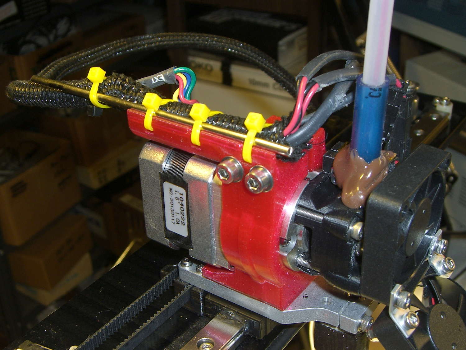
The M2’s extruder motor mounts in a printed holder that attaches to the X-axis linear rail. The wire guide on the original holder snapped when I installed it, with the fractured end showing poor infill and bonding, but the rest of the mount held together and, my initial misgivings notwithstanding, I never had much motivation to print a replacement. With the PETG settings working pretty well, I fetched the updated STL file, oriented it for printing, and ran off a motor mount:
M2 Motor Mount – PETG on platform
That’s at 40% 3D Honeycomb infill, three perimeters and three top/bottom layers, which seems plenty strong enough for the purpose: I can’t bend the wire guide at all, no how, no way!
Despite a few hairs, the nozzle didn’t deposit any boogers. Things are looking up…
A cap should fit over the cable guide, presumably for neatness, but I didn’t see much point in that. Instead, I added a steel rod to support the loom and provide some strain relief beyond the end of the guide, as the wires want to flex at that spot:
M2 Motor Mount – PETG installed – cable brace
Because the V4 hot end mounts to that aluminum plate, rather than the filament drive, the whole operation didn’t disturb the nozzle position at all. Whew!
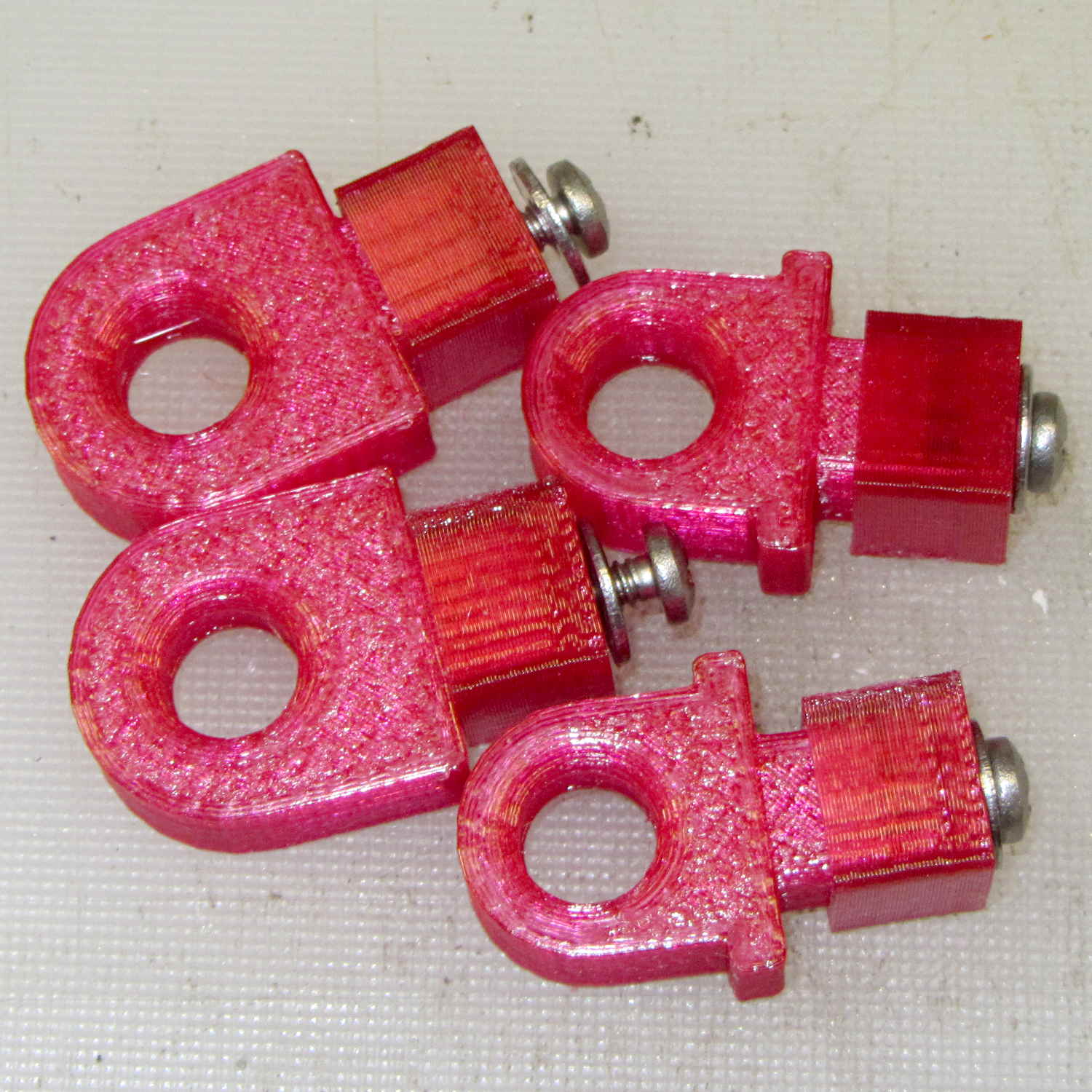
Our Larval Engineer reports that the PLA pivot for the Sienna’s hood rod didn’t survive contact with the van’s NYS Inspection. I’m not surprised, as PLA tends to be brittle and the inspection happened on a typical February day in upstate New York. Seeing as how PETG claims to be stronger and more durable than PLA, I ran off some replacements:
Toyota Sienna hood rod pivot – small – PETG
The square cap fit snugly over the bottom of the post; PETG tolerances seem pretty much the same as for PLA.
A slightly larger loop may be more durable, so I changed one parameter in the OpenSCAD code to get this:
Toyota Sienna Hood Rod Pivot – up-armored – solid model
Which printed just like you’d expect:
Toyota Sienna hood rod pivot – large – PETG hairs
Despite the hairs stretching between each part, the nozzle didn’t deposit any boogers during the print. The top and bottom use Hilbert Curve infill, which looks pretty and keeps the nozzle from zipping back and forth quite so much; perhaps that’s a step in the right direction.
Tapping the holes for 6-32 stainless machines screws went easily enough:
Toyota Sienna hood rod pivot – PETG – assembled
She gets one of each and I keep the others for show-n-tell sessions.
The OpenSCAD source code, which differs from the original by a constant or two:
// Sienna Hood Rod Pivot
// Ed Nisley KE4ZNU November 2013

//- Extrusion parameters must match reality!
//  Print with 2 shells and 3 solid layers

ThreadThick = 0.25;
ThreadWidth = 0.40;

HoleWindage = 0.2;

Protrusion = 0.1;			// make holes end cleanly

inch = 25.4;

function IntegerMultiple(Size,Unit) = Unit * ceil(Size / Unit);

//----------------------
// Dimensions

ShellOD = 20.0;
ShellID = 8.75;
ShellLength = 10.0;

TaperLength = 1.5;
TaperID = 11.4;

BaseWidth = 20.0;
BaseThick = 3.0;

PegSide = 9.5;					// mounting peg through sheet metal
PegLength = 7.0;
PegCornerTrim = 0.75;
PegHoleOD = 0.107*inch;			//  6-32 tap hole

PegTrimSide = sqrt(2)*PegSide - PegCornerTrim;

ClampWall = 3.0;				// clamping cap under sheet metal
ClampHoleOD = 0.150*inch;		//  6-32 clearance hole
ClampCap = 3.0;					// solid end thickness

PanelThick = 2.0;				// sheet metal under hood

NumSides = 6*4;

//----------------------
// Useful routines

module PolyCyl(Dia,Height,ForceSides=0) {			// based on nophead's polyholes

  Sides = (ForceSides != 0) ? ForceSides : (ceil(Dia) + 2);

  FixDia = Dia / cos(180/Sides);

  cylinder(r=(FixDia + HoleWindage)/2,
           h=Height,
	   $fn=Sides);
}

module ShowPegGrid(Space = 10.0,Size = 1.0) {

  Range = floor(50 / Space);

	for (x=[-Range:Range])
	  for (y=[-Range:Range])
		translate([x*Space,y*Space,Size/2])
		  %cube(Size,center=true);

}

//----------------------
// Build it

//ShowPegGrid();

// pivot

translate([-ShellOD,0,0])
	difference() {
		union() {
			cylinder(r=ShellOD/2,h=ShellLength,$fn=NumSides);		// housing
			translate([-ShellOD/2,0,0])								// filler
				cube([ShellOD,(ShellOD/2 + BaseThick),ShellLength],center=false);
			translate([0,(ShellOD/2 + BaseThick/2),ShellLength/2])	// foot
				cube([BaseWidth,BaseThick,ShellLength],center=true);

			translate([0,											// peg
						(ShellOD/2 + PegLength/2 + BaseThick - Protrusion),
						PegSide/2])
				intersection() {
					cube([PegSide,(PegLength + Protrusion),PegSide],center=true);
					rotate([0,45,0])
						cube([PegTrimSide,2*PegLength,PegTrimSide],center=true);
				}
		}

		PolyCyl(ShellID,ShellLength,NumSides);		// central hole

		translate([0,0,-Protrusion])				// end bevels
			cylinder(r1=TaperID/2,r2=ShellID/2,h=(TaperLength + Protrusion),$fn=NumSides);
		translate([0,0,(ShellLength + Protrusion)])
			rotate([180,0,0])
				cylinder(r1=TaperID/2,r2=ShellID/2,h=(TaperLength + Protrusion),$fn=NumSides);

		translate([0,0,PegSide/2])					// screw tap hole
			rotate([-90,0,0])
				PolyCyl(PegHoleOD,(ShellOD + BaseThick + PegLength),6);

	}

// anchor cap

translate([2*PegSide,0,0])
	difference() {
		translate([0,0,(PegLength + ClampCap)/2])					// overall shape
			cube([(PegSide + ClampWall),(PegSide + ClampWall),(PegLength + ClampCap)],center=true);
		translate([0,0,(PegLength/2 + ClampCap + Protrusion)])		// peg cutout
			cube([(PegSide + ThreadWidth),(PegSide + ThreadWidth),(PegLength + Protrusion)],center=true);
		translate([0,0,-Protrusion])								// screw clearance
				PolyCyl(ClampHoleOD,2*PegLength,6);
	}
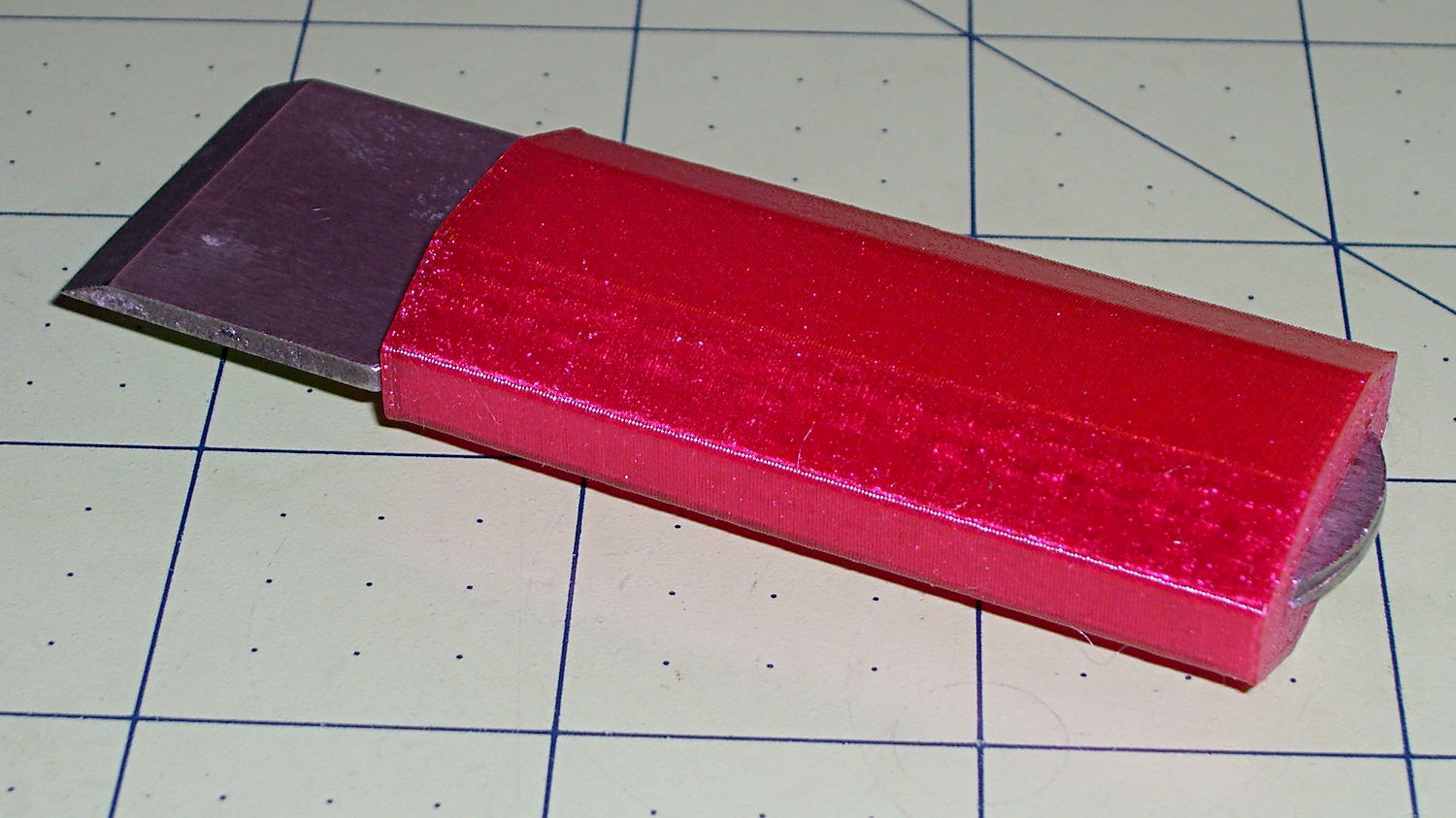
My father used a little chisel for some unknown purpose while he was an instrument repair tech at Olmstead AFB during the mid-60s. Its homebrew wood handle eventually disintegrated and I made a quick-and-truly-dirty replacement from epoxy putty and heatshrink tubing, promising that I’d eventually do better.
Seeing as how I use it to pop objects off the M2’s build platform and being in need of a tall, skinny object to see how PETG works with towers, that chisel now has a nice magenta handle:
Platform Chisel – PETG handle
Well, OK, it may not be the prettiest handle you’ve ever seen, but it’s much better than an epoxy turd, as measured along several axes.
Incidentally, epoxy putty bonds to clean steel like there’s no tomorrow. I had to file the last remaining chunks off and sandpaper the residue down to clean steel again.
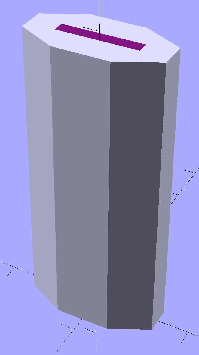
The solid model shows it in build-a-tower mode:
Chisel Handle – solid model
I think at least one rounded end would improve its appearance. Two rounded ends would make it un-printable in that orientation, although a low-vertex polygonal approximation might have enough of a flat bottom to suffice. Given how long it took me to replace the epoxy, that could take a while.
The central slot fits snugly around the handle, requiring persuasion from a plastic mallet to set in in position.
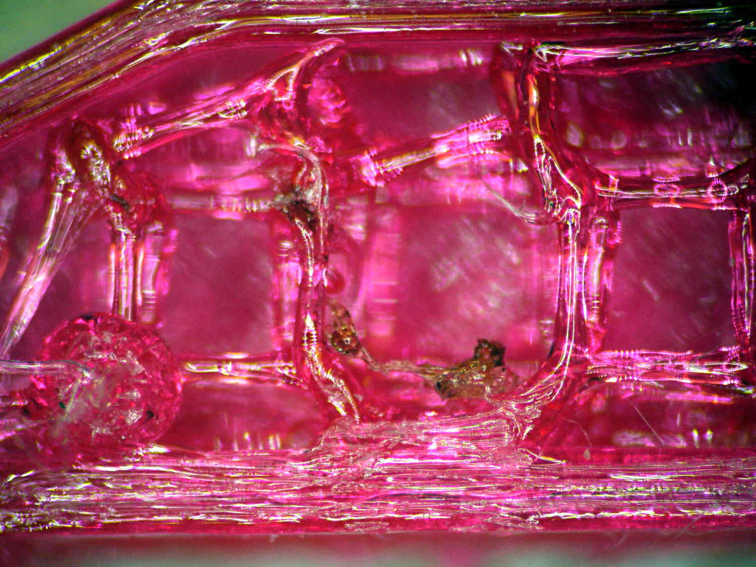
Once again, the nozzle shed a small brown PETG booger after the first few layers:
PETG Chisel Handle – oxidized plastic
I’m beginning to think PETG infill needs more attention than I’ve been giving it: that’s 15% 3D Honeycomb combined over three layers.
The OpenSCAD source code:
// Chisel Handle
// Ed Nisley KE4ZNU - March 2015

Layout = "Show";			// Show Build

//-------
//- Extrusion parameters must match reality!

ThreadThick = 0.25;
ThreadWidth = 0.40;

HoleWindage = 0.2;

Protrusion = 0.1; 				// make holes end cleanly

function IntegerMultiple(Size,Unit) = Unit * ceil(Size / Unit);

//-------
// Dimensions

Shank = [16.0,2.4,59];			// width, thickness, length to arched end

BladeWidth = 27.0;

HandleSides = 8;

//-------

module ShowPegGrid(Space = 10.0,Size = 1.0) {

  RangeX = floor(95 / Space);
  RangeY = floor(125 / Space);

	for (x=[-RangeX:RangeX])
	  for (y=[-RangeY:RangeY])
		translate([x*Space,y*Space,Size/2])
		  %cube(Size,center=true);

}

module PolyCyl(Dia,Height,ForceSides=0) {			// based on nophead's polyholes
  Sides = (ForceSides != 0) ? ForceSides : (ceil(Dia) + 2);
  FixDia = Dia / cos(180/Sides);
  cylinder(r=(FixDia + HoleWindage)/2,h=Height,$fn=Sides);
}


module Handle() {
	difference() {
		scale([1.0,0.5,1.0])
			rotate(180/HandleSides)
				cylinder(d=BladeWidth/cos(180/HandleSides),h=Shank[2],$fn=HandleSides);
		translate([0,0,Shank[2]/2])
			cube(Shank + [0,0,2*Protrusion],center=true);
	}
}

//-------
// Build it!

//ShowPegGrid();

if (Layout == "Show") {
	Handle();
}

if (Layout == "Build") {
	translate([0,0,0])
		rotate([0,0,0])
			Handle();
}
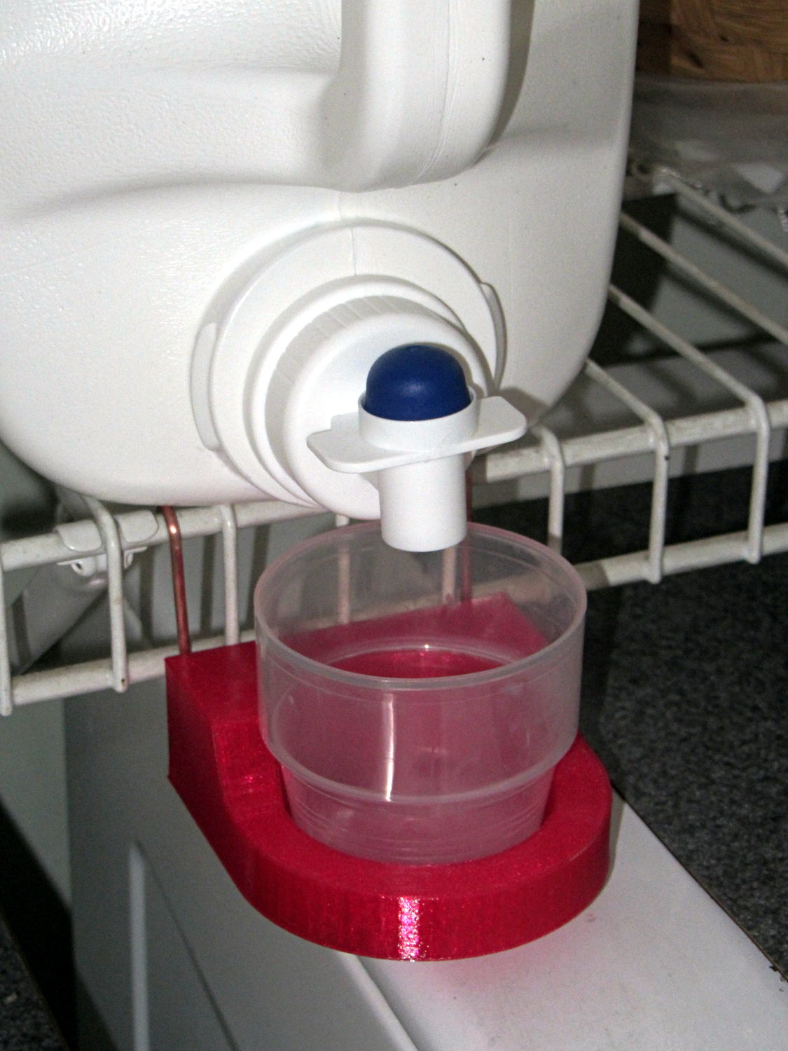
Although chain mail provides a good test of the M2’s setup and slicing parameters, it doesn’t offer much in the way of infill. To test that, I designed a holder for the cap of the bulk laundry detergent container:
Detergent Cap Holder – in place
The container must rest on its side, but if you snap the cap back in place, detergent will ooze out between the cap and the container and drip on whatever’s below. The never-sufficiently-to-be-damned Whirlpool high-efficiency front loading washer vibrates like crazy during the spin cycle, shaking anything from its top to the floor. The cap must sit in a cup to catch the inevitable ooze down its side, the wire shelf already has a bunch of other crap on it, and I needed a bulky test object, soooo ….
We regard that detergent container and its cap as a botched design.
Anyhow.
The holder has pair of holes in its back surface for the copper (!) hangers:
Detergent Cap Holder – solid model – rear
I stripped a length of 10 AWG wire, straightened & annealed it, bent up a pair of hooks, then hammered them just flat enough to work-harden the copper, and they were all good.
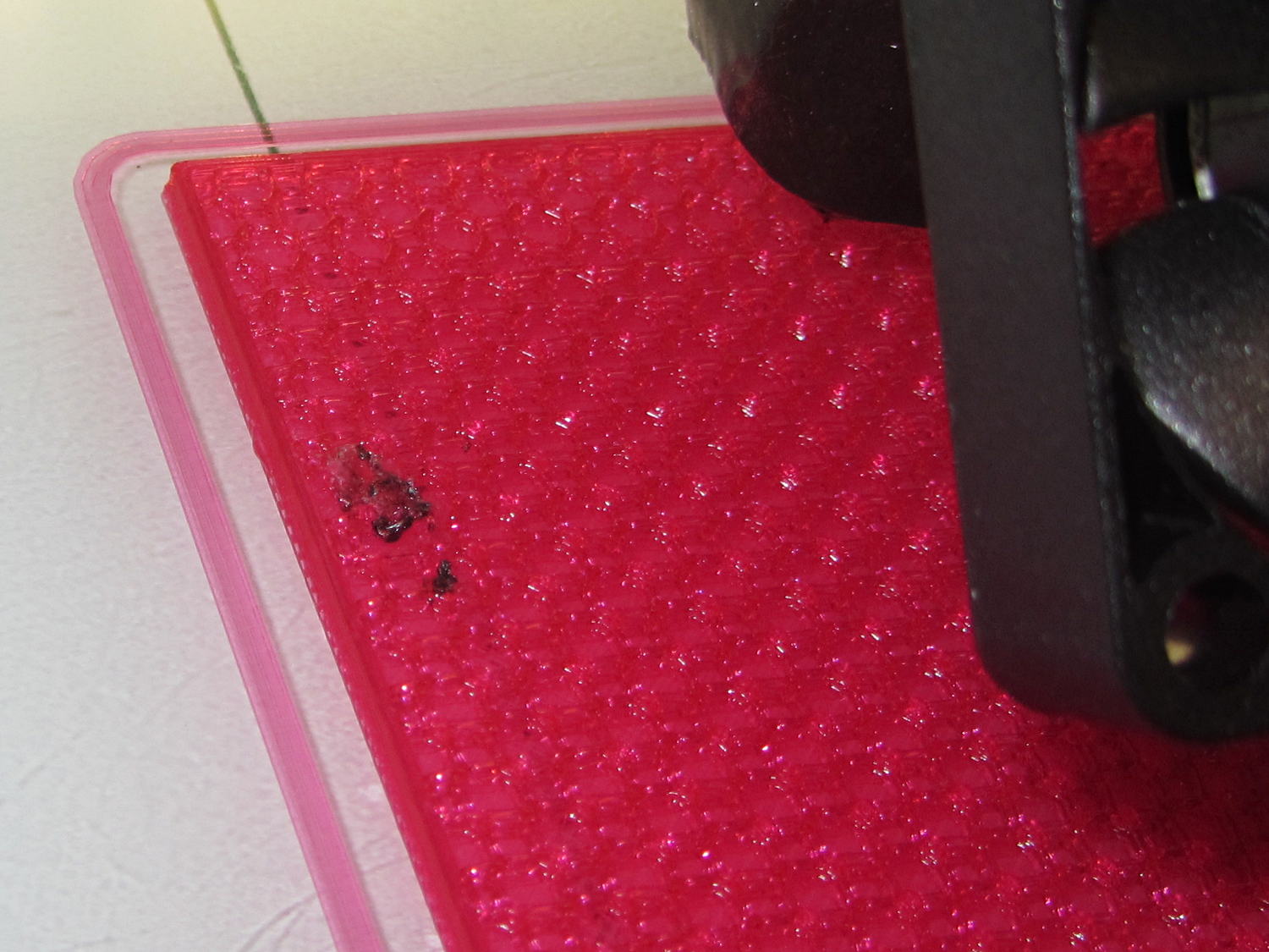
Printing that massive block with 20% infill showed that the nozzle collected enough PETG during the first few layers to leave a substantial booger behind:
Detergent cup holder – oxidized PETG
Fortunately, that was the only one and it ended up on the inside, tucked out of sight.
The PETG deposit on the outside of the nozzle gradually darkens from the original magenta to brown, which I’m pretty sure means that it’s oxidizing / decomposing / going bad. There’s no obvious way to remove the booger during the print; I’ve taken to wiping the nozzle after each object, while it’s still hot and the PETG remains flexible.
Because the nozzle didn’t accumulate any more PETG during the rest of the print, it’s not a constant problem, but I have seen boogers several times so far.
Perhaps continued refinement of the slicing parameters will help? One can always hope…
The OpenSCAD source code:
// Detergent Cap Holder
// Ed Nisley KE4ZNU - March 2015

Layout = "Show";			// Show Build

//-------
//- Extrusion parameters must match reality!

ThreadThick = 0.20;
ThreadWidth = 0.40;

HoleWindage = 0.2;

Protrusion = 0.1; 				// make holes end cleanly

function IntegerMultiple(Size,Unit) = Unit * ceil(Size / Unit);

//-------
// Dimensions

RecessX = 45.0;								// cap recess
RecessDia = 55.0;
RecessDepth = 10.0;
RecessSides = 16*4;

BaseThick = 5.0;							// block thickness below cap

PinDia = 2.5;
PinLength = 20.0;
PinOC = 65.0;
PinInset = 7.0;
PinZ = BaseThick;

Block = [RecessX,PinOC + 2*PinInset,30.0];	// overall block size (X to cap center)

FairingRadius = Block[2] - RecessDepth - BaseThick;

//-------

module ShowPegGrid(Space = 10.0,Size = 1.0) {

  RangeX = floor(95 / Space);
  RangeY = floor(125 / Space);

	for (x=[-RangeX:RangeX])
	  for (y=[-RangeY:RangeY])
		translate([x*Space,y*Space,Size/2])
		  %cube(Size,center=true);

}

module PolyCyl(Dia,Height,ForceSides=0) {			// based on nophead's polyholes
  Sides = (ForceSides != 0) ? ForceSides : (ceil(Dia) + 2);
  FixDia = Dia / cos(180/Sides);
  cylinder(r=(FixDia + HoleWindage)/2,h=Height,$fn=Sides);
}

module Holder() {
	difference() {
		union() {									// main shape
			translate([-Block[0]/2,0,Block[2]/2])
			cube(Block,center=true);
			cylinder(d=Block[1],h=Block[2],$fn=RecessSides);
		}
		for (j=[-1,1])								// mounting pin holes
			translate([-(Block[0] + Protrusion),j*PinOC/2,PinZ])
				rotate([0,90,0]) rotate(180/6)
					PolyCyl(PinDia,PinLength + Protrusion,6);
		translate([0,0,Block[2]])					// fairing arc
			rotate([90,0,0])
				cylinder(r=FairingRadius,h=2*Block[1],center=true);
		translate([Block[0]/2,0,Block[2]/2 + RecessDepth + BaseThick])	// flat top
			scale([1,2,1])
				cube(Block,center=true);
		translate([0,0,BaseThick])
			cylinder(d1=RecessDia,d2=1.1*RecessDia,h=Block[2]);
	}
}

//-------
// Build it!

//ShowPegGrid();

if (Layout == "Show") {
	Holder();
}

if (Layout == "Build") {
	translate([0,0,0])
	rotate([0,0,0])
	Holder();
}
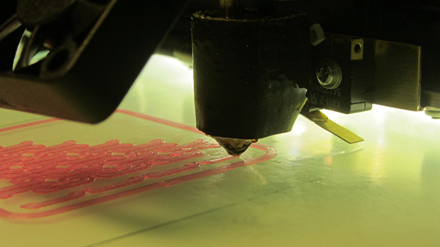
Chain Mail – PETG on nozzle – platform switch clearance
The clearance under that switch lever doesn’t amount to much…
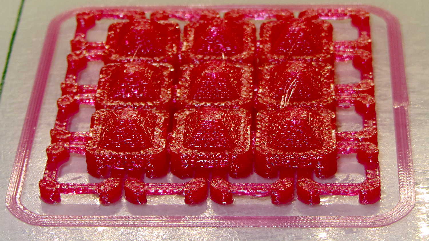
The patch came out looking pretty good, though:
Chain Mail – 4-wide – PETG hairs – bridging
The small red blob on the right side of the nozzle in the first picture tells a tale: the nozzle tends to pull fine hairs from one perimeter to the next, despite 1 mm of retraction. Fiddling with the retraction on subsequent patches didn’t improve matters.
Even though the infill isn’t overstuffed, the nozzle tends to collect and redeposit small amounts of PETG as it travels over the surface. Those small blobs turn into fine hairs when the nozzle moves from one island to the next.
Reducing the bars from six threads to four threads shows that bridging (at 25 mm/s and 0.9 flow rate) seems messier than PLA:
Chain mail – 4 strand PETG bridging
Despite that, all the links came out OK and the sheet was reasonably flexible. After some fiddling with speeds and patterns, these small-link patches popped off the platform easily and were just as flexy as the PLA sheet below them:
Changing from PLA to PETG with a V4 hot end and 24 V power required several slicing adjustments, some of which weren’t at all obvious. It’s not all settled down, but what you see here comes from a bunch of test objects and tweaks that you’ll see over the next few days; this is basically a peek into the future.
M2 V4 Calibration Objects
The obvious changes:
Extrusion temperature: 250 °C
Platform temperature: 90 °C
Hot PETG seems rather sticky and produces hair-fine strings that aren’t due to poor retraction. Running at 230 °C is possible, but the strings are nasty. The V4 hot end shouldn’t run over 250 °C; fortunately, some tests suggest the stringing doesn’t Go Away at 260 °C, so moah powah! isn’t required.
Hair spray on glass works well above 90 °C and not at all below 80 °C. A stick of Elmer’s Washable Glue Stick, chosen because it was on the Adhesive Shelf, produced exactly zero adhesion at any platform temperature I was willing to use. Its “washable” nature surely contributed to the failure; you want something that’s gonna stick with you forever.
The eSun PETG filament diameter varies from 1.63 to 1.72 mm, which seems like a lot compared to the MakerGear PLA I’d been using; I’ve told Slic3r to run with 1.70 mm. In practice, it doesn’t seem to matter; the average over a meter works out to 1.70, I haven’t seen any abrupt bulges, and the objects come out fine. This spool arrived late last year, early in eSun’s production, so perhaps they’ve smoothed things out by now.
A few iterations of thinwall box building put the Extrusion Multiplier at 1.11, producing a spot-on 0.40 mm thread width at either 0.20 or 0.25 mm thread thickness.
Infill:
Infill overlap: 10%
Max infill: 40%
Infill pattern: 3D Honycomb
Top/bottom pattern: Hilbert Curve
Combine infill: 3 layers
The first attempt at a solid box (left of center, first row) became so overstuffed I canceled the print; the top bulges upward. A few parameter tweak iterations produced the perfect 100% filled solid box to its right, but in actual practice a 40% 3D Honeycomb will be entirely strong enough for anything I build.
Reducing the overlap from 15% to 10% reduced the obviously overstuffed junction just inside the perimeter threads.
Cooling:
Fan for layers below 20 s
Minimum layer time: 10 s
Minimum speed: 10 mm/s
PETG wants to go down hot, but printing a single thinwall box requires that much cooling to prevent slumping. Might be excessive; we shall see.
Speeds:
First layer: 15 mm/s
External perimeters: 25 mm/s
Perimeters: 50 mm/s
Infill: 75 mm/s
Travel: 300 mm/s
Slower XY speeds seem to produce better results, although those values aren’t based on extensive experience.
The first layer doesn’t work well at higher speeds, with acute corners and edges pulling up as the nozzle moves away. Using the Hilbert Curve pattern not only looks pretty, but also ensures the nozzle spends plenty of time in the same general area. Higher platform temperatures work better, too, and I may goose the 40 V supply a bit to improve the 0.2 °C/s warmup rate.
The travel speed went up from 250 mm/s in an attempt to reduce stringing, but it may be too aggressive for the Y axis with the new 24 V supply. On very rare occasions, the Y axis stalls during homing, despite not changing the speeds in the startup G-Code, and I’m still accumulating experience with that.
Bridging isn’t nearly as clean as PLA. After some tinkering, a bridge speed of 25 mm/s and flow of 0.90 seems to work, but some chain mail patches suggest there’s plenty of room for improvement.
Mechanically, PETG is softer and more resilient than PLA, with a much higher glass transition temperature. Larger objects with 40% infill are essentially rigid and smaller objects are bendy, rather than brittle.
On the whole, PETG seems like it will work well for the stuff I build, although magenta isn’t my favorite color…
CAUTION: Don’t use this Slic3r configuration unless:
After installing things like imagemagick and mjpg_streamer on the Raspberry Pi, I exhumed a quartet of Logitech cameras from the heap to see how they worked. None bear any identification, apart from a tag on the cable, so here’s what I found out for later reference.
They’re all reasonably good for still pictures, if you don’t mind terrible initial exposures. The default program works OK:
fswebcam -d /dev/video0 -r 320x240 image.jpg
On the other hand, getting any streaming video requires searching through the parameter space, which wasn’t helped by the total lack of documentation. The Arch Linux wiki has a useful summary of camera & drivers, with pointers to additional lists-of-lists. The OctoPrint repo documents the mjpg-streamer plugin parameters.
So, we begin…
This camera, one of two identical cameras in the heap, has a clip that used to fit on the upper edge of a laptop display:
Logitech QuickCam for Notebook Plus – front
One has a tag:
Logitech QuickCam for Notebook Plus – tag
To make the tag data more useful for search engine inquiries:
M/N: V-UBG35
P/N: 861228-0000
PID: CE64105
From lsusb:
Bus 001 Device 008: ID 046d:08d8 Logitech, Inc. QuickCam for Notebook Deluxe
With Raspbian on the RPi, 640×480 video tears and stutters, leaving 320×240 as the least-worst alternative:
The cameras don’t support YUYV at all and the video quality is mediocre, at best, but they do have a manual focus ring that lets you snuggle the camera right up against the subject.
This ball camera:
Logitech QuickCam Pro 5000 – on tripod
Has a tag:
Logitech QuickCam Pro 5000 – tag
Which reads:
M/N: V-UAX16
P/N: 861306-0000
PID: LZ715BQ
From lsusb:
Bus 001 Device 009: ID 046d:08ce Logitech, Inc. QuickCam Pro 5000
It requires YUYV at 320×240 (on the Pi) and nothing else works at all:
It produces even worse video than the Notebook camera.
This HD 720p camera has C130 scrawled on the front in my handwriting:
Logitech HD Webcam C510 – front
And a tag:
Logitech HD Webcam C510 – tag
Bearing this text:
M/N: V-U0016
P/N: 860-000261
PID: LZ114SF
The scrawled C130 doesn’t match up with what lsusb reports:
Bus 001 Device 010: ID 046d:081d Logitech, Inc. HD Webcam C510
It produces very nice results in many resolutions, using YUYV mode, although I think its native resolution is 1280×720 and that works perfectly on the Pi: