The Smell of Molten Projects in the Morning

Ed Nisley's Blog: Shop notes, electronics, firmware, machinery, 3D printing, laser cuttery, and curiosities. Contents: 100% human thinking, 0% AI slop.

Category: Machine Shop

Mechanical widgetry

  • Sewing Machine RPM Sensing: Gun Bluing FTW!

    A quick-and-dirty bracket (made from a leftover strip in the pile of chassis clips) affixed an IR reflective sensor (based on the ubiquitous TCRT5000 module) to the sewing machine motor:

    TCRT5000 sensor on motor
    TCRT5000 sensor on motor

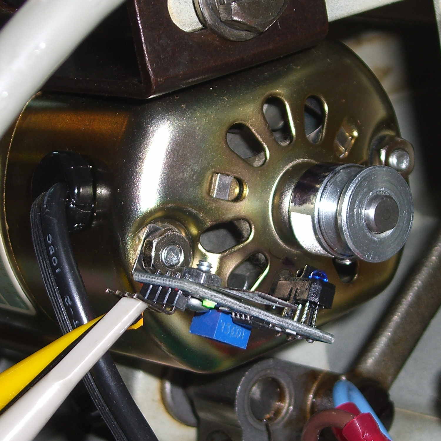
    That’s scribbling black Sharpie around the retroreflective tape for the laser tachometer, which worked just about as poorly as you’d expect. Retroreflective tape, by definition, reflects the light directly back at the LED, but in this case you want it bounced to the photosensor.

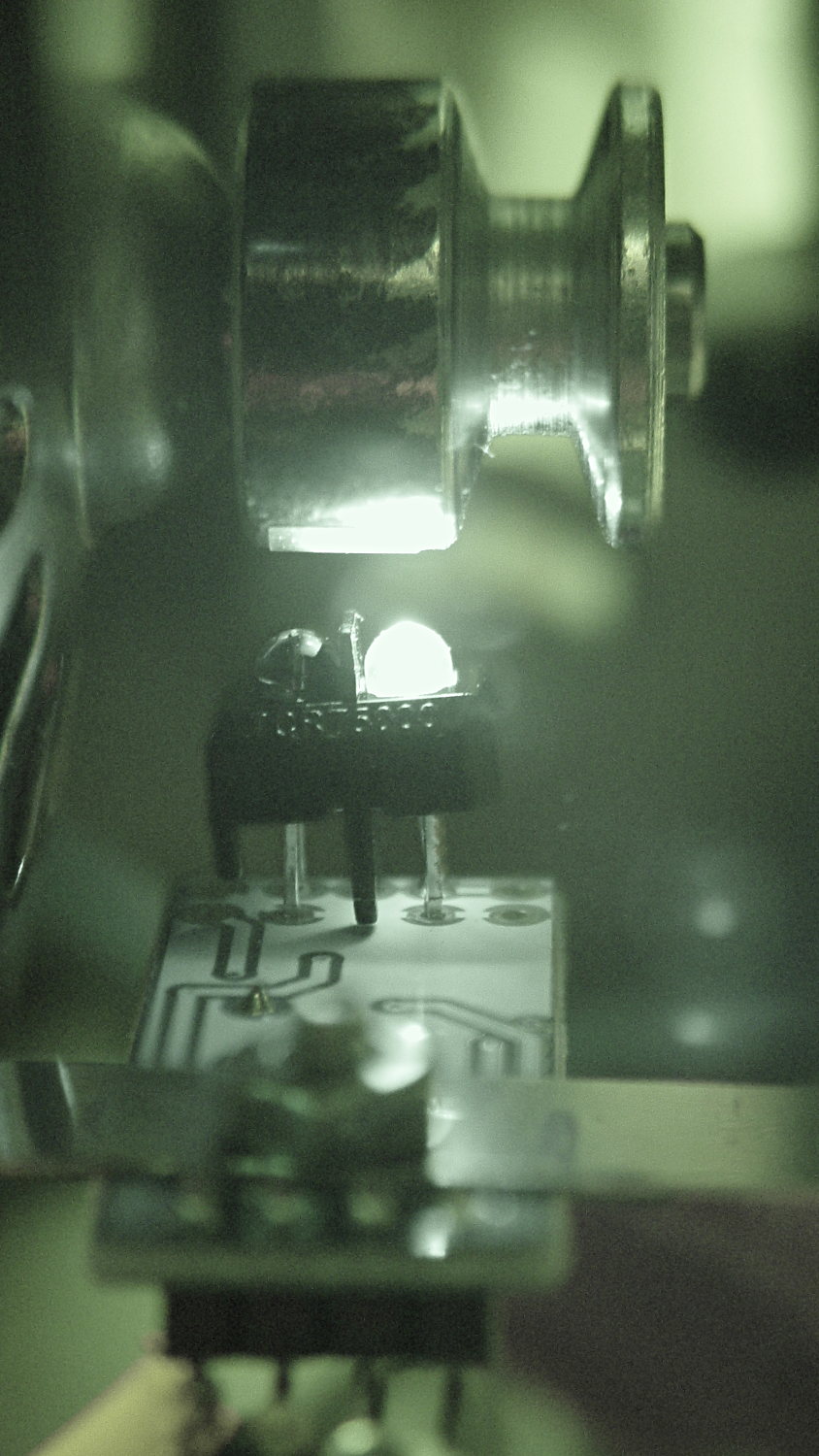
    An IR view shows the geometry and highlights the LED:

    TCRT5000 sensor - IR view
    TCRT5000 sensor – IR view

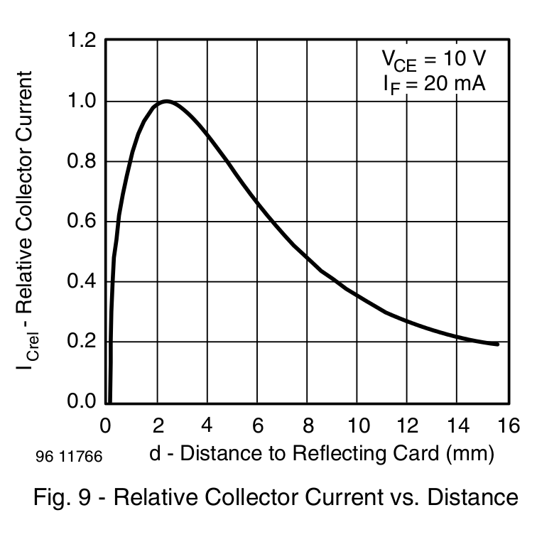
    The TCRT5000 datasheet suggests that the peak operating distance is 2.5 mm, roughly attained by tinkering with the bracket. The datasheet graph shows that anything between 1 and 5 mm should be just fine:

    IR Reflective Sensor module - TCRT5000 - response vs distance
    IR Reflective Sensor module – TCRT5000 – response vs distance

    Soooo, a bit of contrast improvement is in order:

    • Scrape off the tape
    • Remove adhesive and Sharpie with xylene
    • Scuff with sandpaper
    • Apply Brownell’s Oxpho-Blue gun bluing with a cotton swab
    • Buff with 0000 steel wool
    • Repeat
    • Apply stainless steel tape around half the circumference
    • Burnish flat

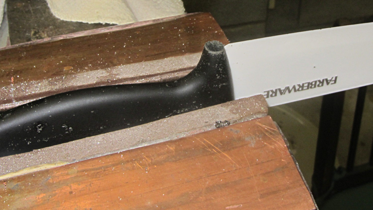
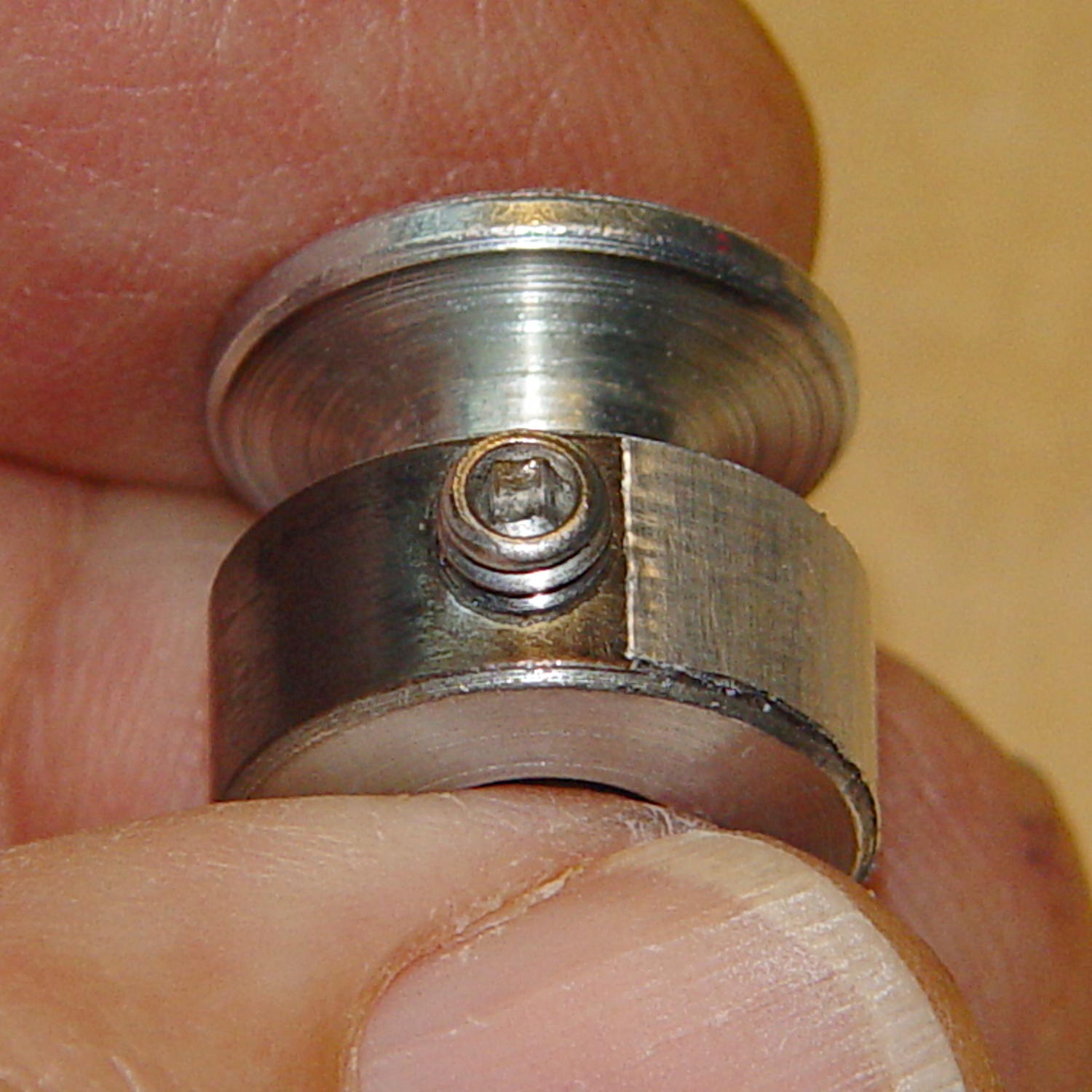
    Which looks pretty good:

    Kenmore 158 motor pulley - black-silver
    Kenmore 158 motor pulley – black-silver

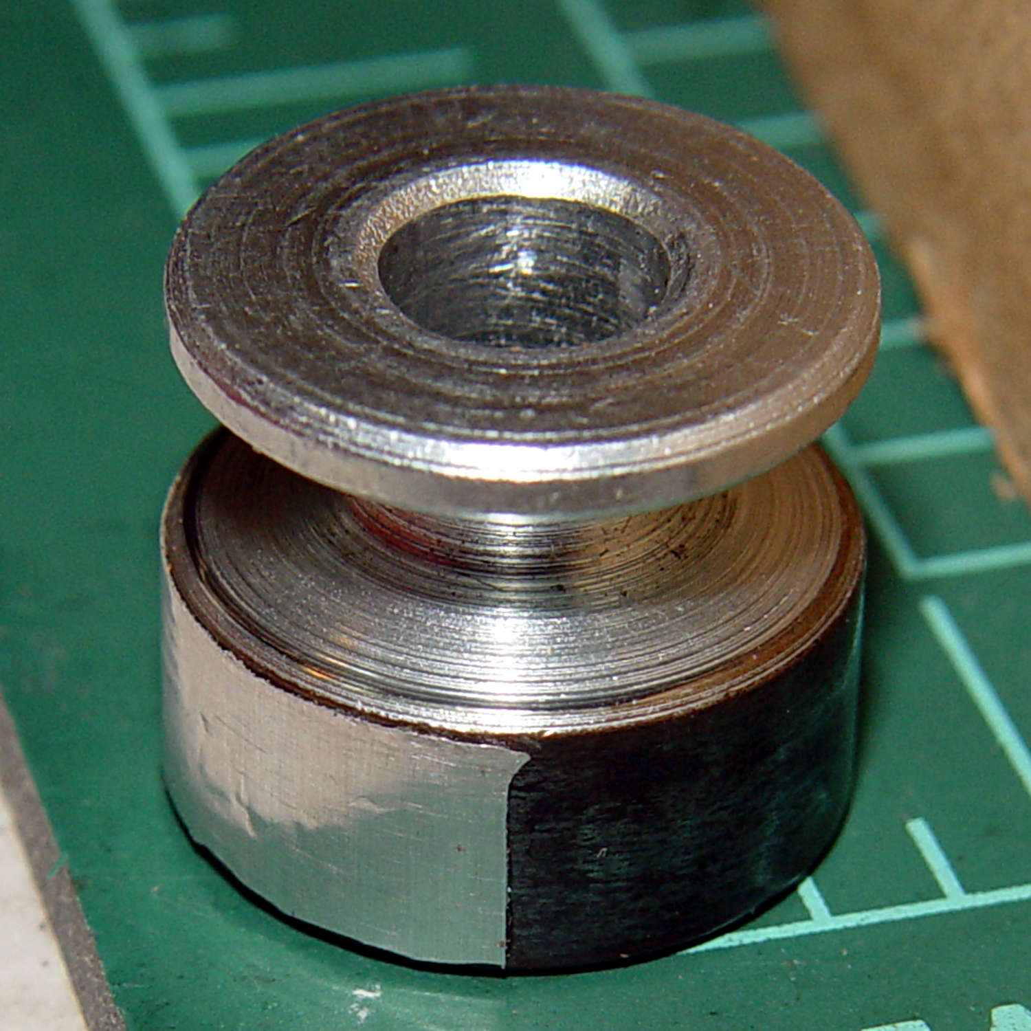
    The stainless tape butts up against the setscrew:

    Kenmore 158 motor pulley - black-silver at setscrew
    Kenmore 158 motor pulley – black-silver at setscrew

    Adjusting the sensitivity midway between the point where the output is low (OFF) over the black and high (ON) over the tape seems reasonable.

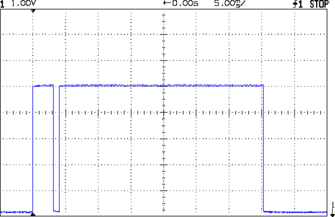
    Running at the slowest possible speed produces this pulse train:

    Motor sense - min speed
    Motor sense – min speed

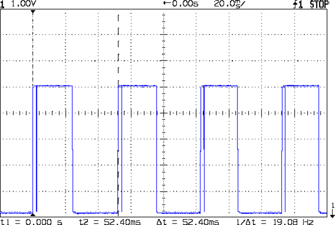
    The motor at 19 rev/s = 1140 RPM corresponds to about 2 rev/s of the sewing machine shaft= 2 stitch/s. Slower than, that, the pedal won’t go in simple open-loop mode.

    The setscrew causes those “glitches” on the rising edge. They look like this at a faster sweep:

    Motor sense - min speed - setscrew
    Motor sense – min speed – setscrew

    At maximum speed, the setscrew doesn’t show up:

    Motor sense - max speed
    Motor sense – max speed

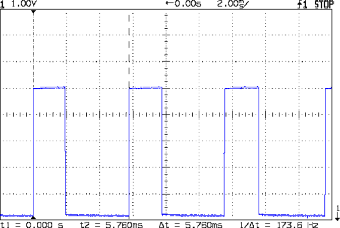
    The motor at 174 rev/s = 10440 RPM would do 1000 stitch/s, but that’s just crazy talk: it runs at that speed with the handwheel clutch disengaged and the motor driving only the bobbin winder. I was holding the machine down with the shaft engaged and all the gimcrackery flailing around during that shot.

    The sensor board may have an internal glitch filter, but it’s hard to say: the eBay description has broken links to the circuit documentation.

    I could grind the setscrew flush with the pulley OD and cover it with tape, but that seems unreasonable. Fixing the glitch in firmware shouldn’t be too difficult: ignore a rising edge that occurs less than, say, 1/4 of the previous period following the previous edge.

    Perhaps buffing half the pulley’s circumference to a reasonable shine (minus the bluing) would eliminate the need for the stainless steel tape.

    Iterating the bluing operation / scrubbing with steel wool should produce a darker black, although two passes yields a nice flat black.

  • Search Engine Optimization: Replacement Shelf Bracket Whirlpool Freezer

    If I were selling those brackets, I’d be rich:

    Search Engine Optimization - Freezer Shelf Bracket
    Search Engine Optimization – Freezer Shelf Bracket

    Now, that looks like Search Engine Optimization it is to die for! Google will give you a different set of pictures, but I own that all-important top row.

    Alas, anybody can just print their own…

  • Crysknife Modification

    For whatever reason, the handle of the ceramic knife extended a few millimeters below the blade heel:

    Farberware ceramic knife
    Farberware ceramic knife

    Now it doesn’t:

    Farberware ceramic knife - trimmed handle
    Farberware ceramic knife – trimmed handle

    Which makes it much more usable for the kind of chopping I do around here: the blade hits the cutting board squarely, producing chunks of veggies along its entire length.

    A coarse file removed most of the stub, followed with a fine file and a little sandpaper action to round the edges.

    Amazingly enough, none of that fussing around touched the blade, nor did I gash myself!

  • LV Interface Board: +7 V Regulator

    This takes most of the load off the Arduino Pro Mini’s teeny SMD regulator by knocking the +12 V ATX supply down to +7 V:

    LV Power Interface - 7 V Regulator
    LV Power Interface – 7 V Regulator

    It’s on the heatsink beyond the ATX connector at the right edge of the board:

    Low Voltage Interface Board - detail
    Low Voltage Interface Board – detail

    It also provides a (more) stable voltage for the current sense amp than you can reasonably expect directly from the ATX power supply:

    Current Sense Amp - schematic
    Current Sense Amp – schematic

    Not much to it: the thing Just Works…

  • Optoisolated ET227 Transistor Driver

    Because the ET227 transistor operates at power line voltages through a full wave rectifier, the base drive circuit requires an optoisolator. The ET227 is a low-gain device with hFE < 10, so it takes about 100 mA of base drive to control an amp of motor current, soooo the optoisolator needs a current amplifier.

    I used an MJE2955T PNP transistor, with the emitter powered from an isolated +5 V supply to let the optoisolator pull current from the base. You could use an NPN transistor as a Darlington amp, but wiring the collectors together means the driver dissipates way too much power; the PNP seemed all-around easier.

    That circuitry sprawls across the middle of the schematic:

    AC Power Interface
    AC Power Interface

    The ET227 base runs at about 900 mV, so the MJE2955 PNP transistor will dissipate half a watt and needs a little heatsink, seen over on the right (with the hulking ET227 heatsink at the edge):

    HV Interface board - detail
    HV Interface board – detail

    With all those parts safely secured, I ran some end-to-end current measurements from the optoisolator’s LED to the ET227’s collector current, with a safe 10 VDC applied to the collector:

    ET227 - base drive - optoisolators
    ET227 – base drive – optoisolators

    It’s worth noting that the two optoisolators have different pinouts. The DIP socket has wiring for both of ’em, so I could swap the two without rewiring the board. No, I didn’t notice that the first time around.

    The curves are nicely linear above 250 mA, which is about what you’d expect for bipolar transistors driven from a current source. Below that, the current into the 13 Ω base-emitter resistor starts to overwhelm the actual base junction current and makes the curves all bendy. Given that the motor doesn’t start spinning the sewing machine with less than half an amp, that region doesn’t matter.

    It’s also worth noting that the ET227 normally sees tens of amps (!) into the base terminal to control up to 200 A pulsed collector current with up to 1 kV collector voltage. That puppy loafs along here…

    The ratio between the isolator gains doesn’t match the ratio between the spec sheet values, so maybe they’re mismarked or I (once again) have an outlier. In any event, there’s no point in getting too fussy, because the transistor gains depend strongly on temperature. I picked the lower-gain SFH6106-2 for more headroom, but it probably doesn’t make much difference.

    The voltage-to-current circuitry driving the optoisolator’s LED lives on the Low Voltage Interface board, with the MCP4725 DAC breakout board above the Arduino Pro Mini and the rest just beyond the LM324 op amp over on the left:

    Low Voltage Interface Board - detail
    Low Voltage Interface Board – detail

    There’s nothing much to it:

    Current Control DAC and Driver - schematic
    Current Control DAC and Driver – schematic

    I finally broke down and got some of Adafruit’s nice MCP4725 I2C DAC breakout boards: 12 bits, rail-to-rail output, no PWM ripple. What’s not to like?

    R409 scales the gain so that +5 V tops out around 1.5 mA, which should deliver a collector current around 3 A: far more than seems absolutely necessary. R408 lets the op amp develop some voltage while trickling a few dozen microamps into the 2N3904’s base; the hFE runs around 50, so the error due to base current amounts to maybe 2% and, remember, the final current depends on the temperature anyway.

    It’s getting closer to working…

  • Kenmore 158: LED Strip Light Cable Clips

    Commercial LED strip lights for sewing machines mount their cables with little stick-on anchors and cable ties. I wasn’t happy with the cable tie thing and finally figured this out:

    Kenmore 158 - LED strip light cable clips
    Kenmore 158 – LED strip light cable clips

    The clips have that size & shape because they fit exactly atop some pre-cut foam squares from the Tape Lookaside Buffer:

    LED strip light cable clips
    LED strip light cable clips

    You can see the shape better in the solid model:

    LED Cable Clips
    LED Cable Clips

    The central bollard has a slight taper to retain the cable, the quarter-posts are straight, and they’re both twice the cable diameter tall. The clearance between the center and corner posts at the top matches the cable diameter, so there’s a bit of bending room at the bottom, and, with the cable bent around the center, it won’t fall out on its own.

    The cute coaxial cable I’m misusing for the LED strips measures just shy of 2 mm, making these into little bitty things. The corner posts seem surprisingly strong, despite 3D printing’s reputation for crappy quality; I haven’t been able to break one off with more effort than seemed warranted.

    The OpenSCAD source code:

    // LED Cable Clips
    // Ed Nisley - KE4ZNU - October 2014
    
    //- Extrusion parameters must match reality!
    
    ThreadThick = 0.20;
    ThreadWidth = 0.40;
    
    HoleWindage = 0.2;			// extra clearance
    
    Protrusion = 0.1;			// make holes end cleanly
    
    AlignPinOD = 1.70;			// assembly alignment pins: filament dia
    
    function IntegerMultiple(Size,Unit) = Unit * ceil(Size / Unit);
    
    //----------------------
    // Dimensions
    
    Base = [12.0,12.0,IntegerMultiple(2.0,ThreadThick)];	// base over sticky square
    
    CableOD = 2.0;
    
    BendRadius = 3.0;
    
    Bollard = [BendRadius,(sqrt(2)*Base[0]/2 - CableOD - BendRadius),2*CableOD];
    B_BOT = 0;
    B_TOP = 1;
    B_LEN = 2;
    
    NumSides = 5*4;
    
    //----------------------
    // Useful routines
    
    module PolyCyl(Dia,Height,ForceSides=0) {			// based on nophead's polyholes
    
      Sides = (ForceSides != 0) ? ForceSides : (ceil(Dia) + 2);
    
      FixDia = Dia / cos(180/Sides);
    
      cylinder(r=(FixDia + HoleWindage)/2,
               h=Height,
               $fn=Sides);
    }
    
    module ShowPegGrid(Space = 10.0,Size = 1.0) {
    
      RangeX = floor(100 / Space);
      RangeY = floor(125 / Space);
    
    	for (x=[-RangeX:RangeX])
    	  for (y=[-RangeY:RangeY])
    		translate([x*Space,y*Space,Size/2])
    		  %cube(Size,center=true);
    
    }
    
    //----------------------
    // Build it
    
    ShowPegGrid();
    
    intersection() {
    	translate([0,0,(Base[2] + Bollard[2])/2])			// overall XYZ outline
    		cube(Base + [0,0,Bollard[2]],center=true);
    	
    	union() {
    		translate([0,0,Base[2]/2])						// oversize mount base
    			scale([2,2,1])
    				cube(Base,center=true);
    				
    		for (i=[-1,1] , j=[-1,1]) {						// corner bollards
    			translate([i*Base[0]/2,j*Base[1]/2,(Base[2] - Protrusion)])
    				rotate(180/NumSides)
    				cylinder(r=Bollard[B_BOT],h=(Bollard[B_LEN] + Protrusion),center=false,$fn=NumSides);
    
    		translate([0,0,(Base[2] - Protrusion)])			// center tapered bollard
    			cylinder(r1=Bollard[B_BOT],r2=Bollard[B_TOP],h=(Bollard[B_LEN] + Protrusion),center=false,$fn=NumSides);
    		}
    	}
    }
    

    Now that I think of it, maybe a round clip would look nicer. The central bollard would stay, but the circular outside rim could have three cutouts. When these fall off, I’ll give that a try.

    They may be square and clunky, but they look much better than Gorilla Tape…


  • Model 158 Sewing Machine Controller: AC Interface Circuitry

    That polycarbonate slab holds most of the pieces in place, with the rest on the prototype board to the left of the monster heatsink:

    Model 158 Controller - Interior Overview
    Model 158 Controller – Interior Overview

    That bulky wire harness got bent out of the way for the photo; normally, it’s jammed down beside the ATX power supply and over the blower.

    The AC Interface circuitry looks like this:

    AC Power Interface
    AC Power Interface

    The relay on the top disconnects the AC line from the circuitry when the clamshell case opens.

    The key hardware spreads neatly across the middle: the optoisolator, a 2955 PNP power transistor in a TO-220 case on a heatsink as a current amplifier, and the ET227 controlling the motor current. The gain of that mess depends strongly on the transistor temperatures, so there’s not much point in calibrating it. More on that later.

    Down at the bottom of the schematic is the slit toroid and knockoff SS49(E) Hall effect sensor that senses the actual motor current.

    A closer look at that board:

    HV Interface board - detail
    HV Interface board – detail

    The board in the bottom left corner of the overview picture holds the Arduino Pro Mini that runs the whole show (so far, anyway), along with various & sundry analog circuitry that I’ll write up in a bit.

    Conspicuous by their absence:

    • Motor speed sensing
    • Shaft position sensing
    • Power to the LED strip lights
    • Permanent mount for the pedal cable socket

    Now I can make measurements without killing myself…