Ed Nisley's Blog: Shop notes, electronics, firmware, machinery, 3D printing, laser cuttery, and curiosities. Contents: 100% human thinking, 0% AI slop.
Recently, the eye cups became difficult to pull out. The problem seemed to lie in the seal around the exterior of each tube, rather than with the internal mechanism, so I eased the tiniest possible drop of clock oil into each gap, spun the tubes, cycled them in-and-out, and wiped off essentially all of the oil as it spread over the exterior of the tubes.
The eye cups work fine again!
Frankly, I felt a like a Visigoth upgrading the Large Hadron Collider, but I trusted those old-school Leitz engineers would protect their optics from everything happening outside the sealed tubes.
For reasons not relevant here, I need a tripod mount for the Sony AS-30V that’s not quite so constraining as Sony’s Official skeleton mount + right-angle tripod bracket:
Sony HDR-AS30V – skeleton tripod mount
I must run a cable from the micro-HDMI port behind the hatch on the bottom of the camera to a display, but the Sony mount puts the hatch directly over the tripod platform and handle. Reversing the camera points it toward the handle, which then appears in the camera’s not-quite-fisheye view. Flipping the camera upside down sends the cable out the top, where it will put what I consider undue stress on the smallest high-density connector on any of my gadgets.
This Thingiverse model by maxspongebob is called a “Windshield Mount“, but has approximately the right features:
Sony HDR-AS30V holder – on tripod
The weird T-shaped dingus adapts micro- and mini-HDMI sockets to an ordinary HDMI cable (HDMI connector Types D, C, and A, respectively), serving as a placeholder for the yet-to-arrive 15 foot (probably 4.5 meter) cable.
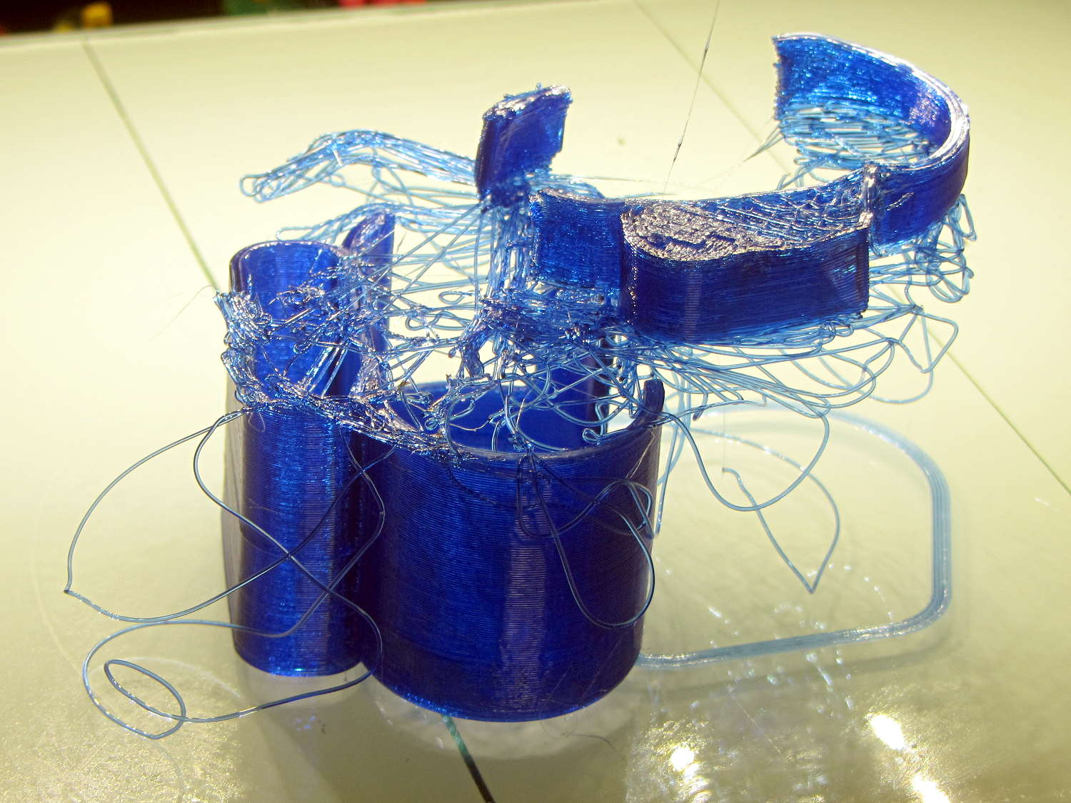
The mount isn’t designed for easy 3D printing, as it includes thin walls with chamfered edges, close tolerances, and aggressive bridging in dimension-critical areas. The first attempt failed when the minimal footprint (you’re looking at it in the picture above) pulled off the platform when the nozzle hit the lower bridge in the battery compartment:
Sony HDR-AS30V holder – failed print
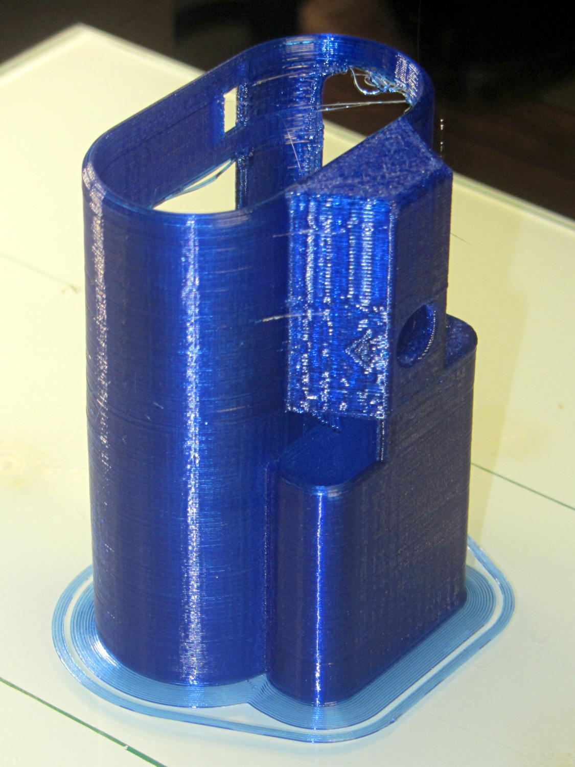
Surrounding the first layer with a 5 mm brim provided enough traction to finish the whole thing:
Sony HDR-AS30V holder – on platform
You can see some droopy threads across the openings; PETG bridges reasonably well, but the chamfers don’t provide good anchors. The opening for the camera hatch (on the far right rear) turned out slightly too short or, perhaps, the camera doesn’t seat quite far enough forward, which required some abrasive adjustment to accommodate the hatch.
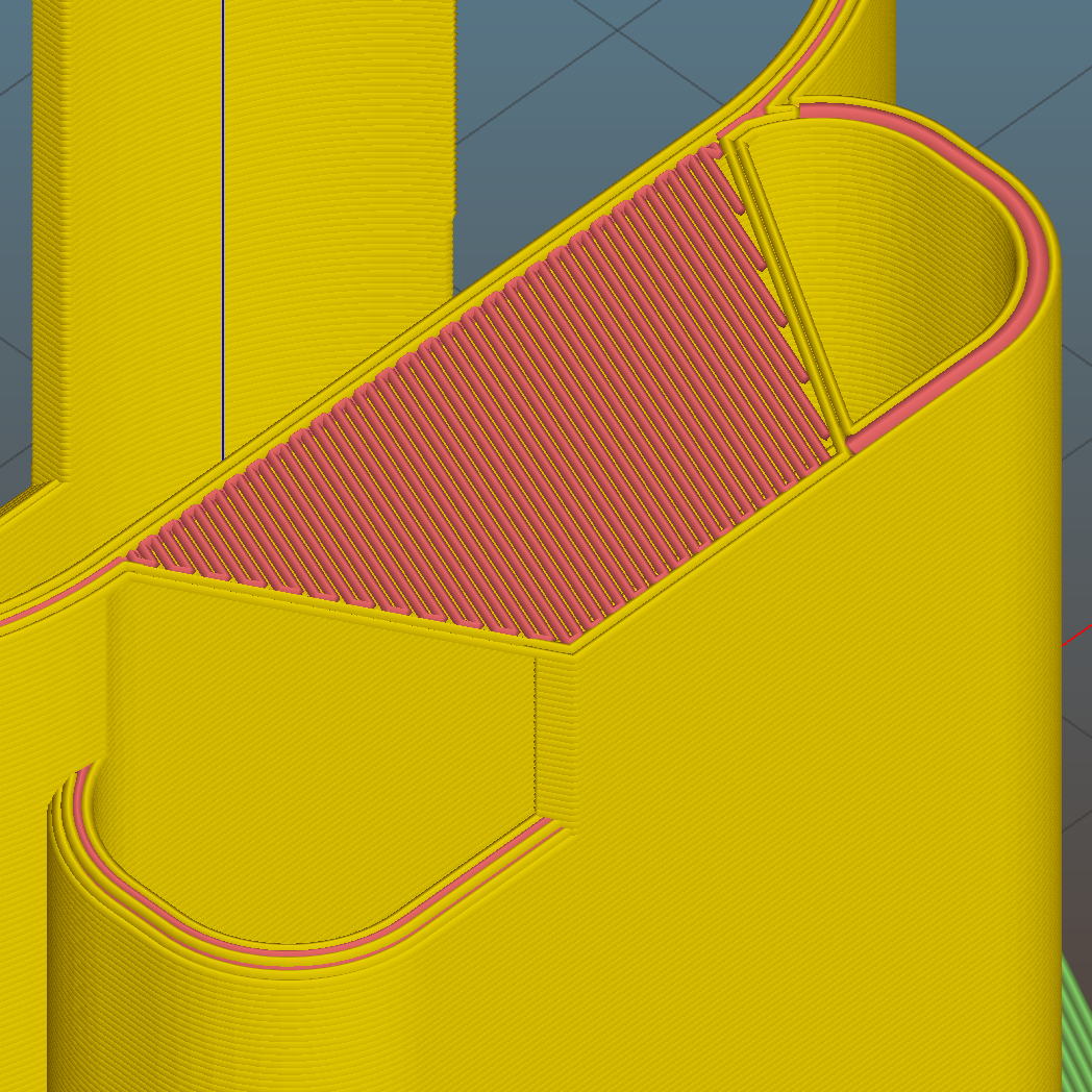
For unknown reasons, the top end of the battery compartment has a trapezoidal bridge:
Sony HDR-AS30V holder – trapezoidal bridge – Slic3r preview
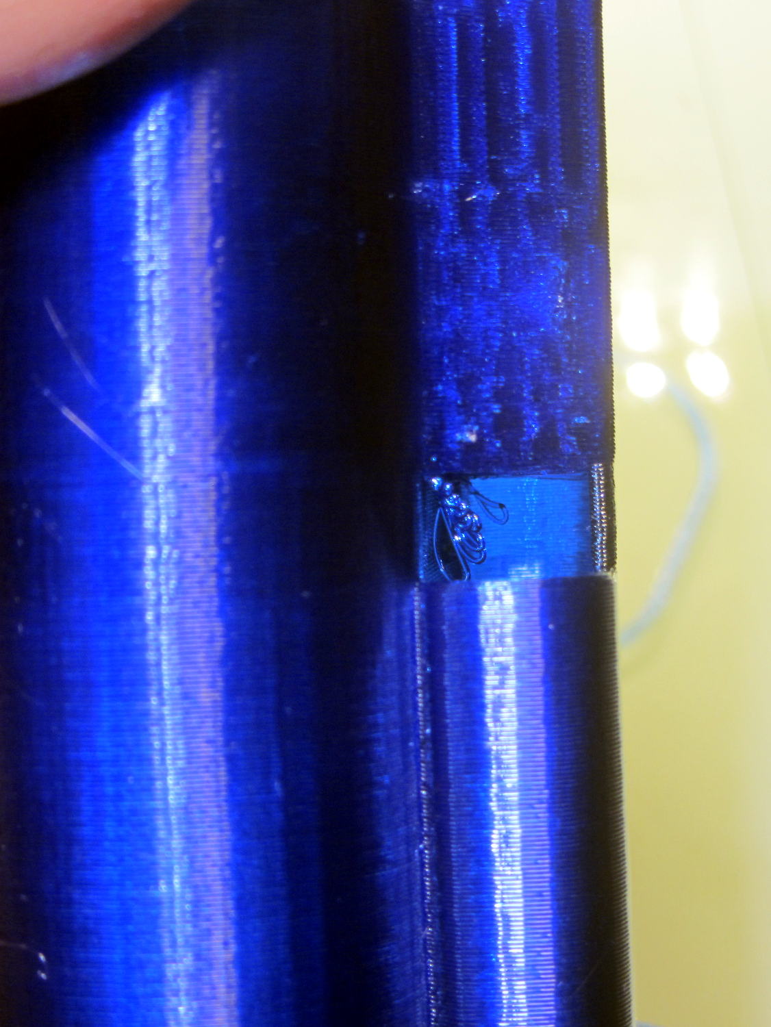
Which simply cannot be printed:
Sony HDR-AS30V holder – internal bridge failure
Cutting those threads out with an Xacto knife solved that problem.
The mount attaches to the tripod with a 1/4-20 nut trapped behind the hole next to the battery compartment. I grabbed an ordinary steel nut in a long normally closed tweezers, heated it over a butane lighter flame, threaded it onto a bolt stuck through the hole, and pulled it securely into the trap with exactly zero drama.
It has a very, very snug fit around the camera and battery that’s much better than a loose & floppy fit: there’s no positive retention latch.
This will serve as a prototype to see if the whole project works. If so, I’ll lash something together in OpenSCAD that should print a bit better, even if it looks like my usual brackets…
A trio of N2O cartridges / capsules made their way into the Basement Laboratory and cried out to be fitted with fins:
N2O Capsule Fins – installed
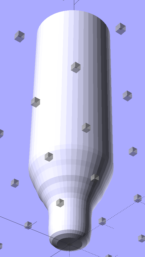
My original model tinkered up a cartridge from solid object primitives, but I’ve since discovered that cheating produces a much better and faster and easier result for cylindrical objects:
N2O Capsule – solid model – bottom view
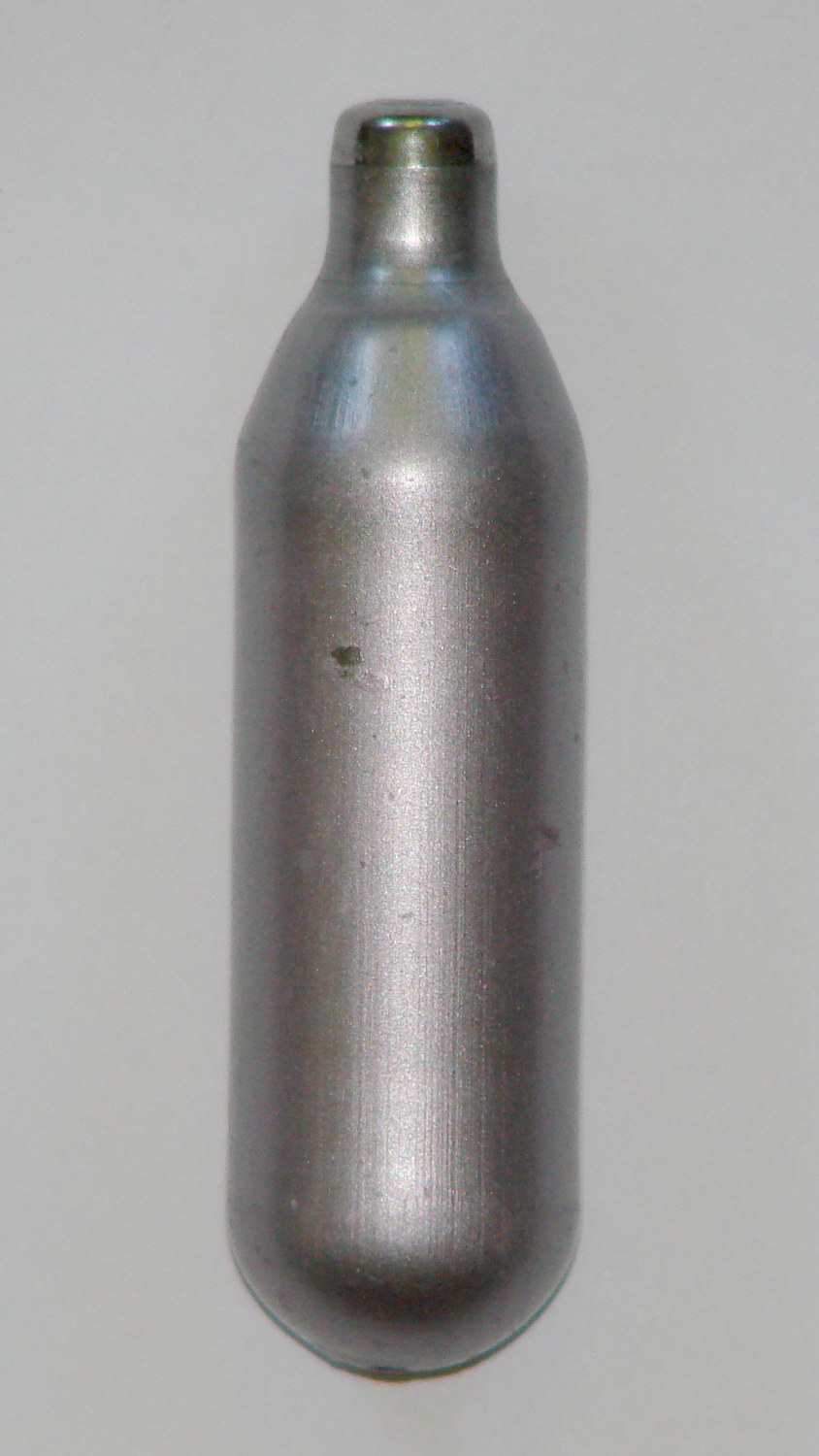
The trick is getting an image of the original object from the side, taken from far enough away to flatten the perspective:
N2O capsule – side view
Then overlay and scale a grid to match the actual length:
N2O capsule – grid overlay
The grid has 1 mm per minor square, centered along the cartridge’s axis, and zeroed at the tip; I rotated the cartridge image by half a degree to line it up with the grid.
Print it out on actual paper so you can eyeball the measurements and write ’em where you need ’em:
N2O capsule – grid overlay – printed
Which becomes an OpenSCAD polygon definition:
RADIUS = 0;				// subscript for radius values
HEIGHT = 1;				//   ... height above Z=0 at seal flange

//-- N2O 8 g capsule

CartridgeOutline = [			// X values = measured radius, Y as distance from tip
	[0.0,0.0],					//  0 cartridge seal tip
	[2.5,0.1],					//  1 seal disk
	[3.5,0.5],[4.0,1.0],		//  2 tip end
	[4.2,2.0],[4.3,3.0],		//  4 tip
	[4.3,6.0],					//  6 chamfer
	[4.5,8.0],					//  7 taper
	[4.9,9.0],					//  8
	[5.5,10.0],					//  9
	[6.0,11.0],					// 10
	[6.7,12.0],					// 11
	[7.1,13.0],					// 12
	[7.5,14.0],					// 13
	[8.0,15.0],					// 14
	[8.4,16.0],					// 15
	[8.8,17.0],					// 16
	[9.0,18.0],[9.0,58.0],		// 17 body
	[0.0,65.0]					// 19 dummy end cone
	];

TipLength = CartridgeOutline[6][HEIGHT];
TipOD = 2*CartridgeOutline[5][RADIUS];

BodyOD = 2*CartridgeOutline[17][RADIUS];
BodyOAL = CartridgeOutline[19][HEIGHT];
Because the rounded end of the cartridge doesn’t matter, I turned it into a cone.
Which then punches a matching dent in the fin structure:
Gas Capsule Fins – Slic3r preview
The lead picture doesn’t quite match the Slic3r preview, as I found the single-width diagonal fins weren’t strong enough. Making them two (nominal) threads wide lets Slic3r lay down three thinner threads in the same space:
Gas Capsule Fins – thicker – Slic3r preview
That’s letting Slic3r automagically determine the infill and perimeter thread width to make the answer come out right. As nearly as I can tell, the slicing algorithms have become smart enough to get the right answer nearly all of the time, so I can-and-should relinquish more control over the details.
The OpenSCAD source code:
// CO2 capsule tail fins
// Ed Nisley KE4ZNU - October 2015
Layout = "Build"; // Show Build FinBlock Cartridge Fit
//-------
//- Extrusion parameters must match reality!
// Print with +0 shells and 3 solid layers
ThreadThick = 0.25;
ThreadWidth = 0.40;
HoleWindage = 0.2;
Protrusion = 0.1; // make holes end cleanly
function IntegerMultiple(Size,Unit) = Unit * ceil(Size / Unit);
//-------
// Capsule dimensions
CartridgeSides = 12*4; // number of sides
RADIUS = 0; // subscript for radius values
HEIGHT = 1; // ... height above Z=0 at seal flange
//-- N2O 8 g capsule
RW = HoleWindage/2; // enlarge radius by just enough
CartridgeOutline = [ // X values = measured radius, Y as distance from tip
[0.0,0.0], // 0 cartridge seal tip
[2.5 + RW,0.1], // 1 seal disk
[3.5 + RW,0.5],[4.0 + RW,1.0], // 2 tip end
[4.2 + RW,2.0],[4.3 + RW,3.0], // 4 tip
[4.3 + RW,6.0], // 6 chamfer
[4.5 + RW,8.0], // 7 taper
[4.9 + RW,9.0], // 8
[5.5 + RW,10.0], // 9
[6.0 + RW,11.0], // 10
[6.7 + RW,12.0], // 11
[7.1 + RW,13.0], // 12
[7.5 + RW,14.0], // 13
[8.0 + RW,15.0], // 14
[8.4 + RW,16.0], // 15
[8.8 + RW,17.0], // 16
[9.0 + RW,18.0],[9.0 + RW,58.0], // 17 body
[0.0,65.0] // 19 dummy end cone
];
TipLength = CartridgeOutline[6][HEIGHT];
TipOD = 2*CartridgeOutline[5][RADIUS];
CylinderBase = CartridgeOutline[17][HEIGHT];
BodyOD = 2*CartridgeOutline[17][RADIUS];
BodyOAL = CartridgeOutline[19][HEIGHT];
//-------
// Fin dimensions
FinThick = 1.5*ThreadWidth; // outer square
StrutThick = 2.0*ThreadWidth; // diagonal struts
FinSquare = 1.25*BodyOD;
FinTaperLength = sqrt(2)*FinSquare/2 - sqrt(2)*FinThick - ThreadWidth;
FinBaseLength = 0.7 * CylinderBase;
FinTop = 0.9*CylinderBase;
//-------
module PolyCyl(Dia,Height,ForceSides=0) { // based on nophead's polyholes
Sides = (ForceSides != 0) ? ForceSides : (ceil(Dia) + 2);
FixDia = Dia / cos(180/Sides);
cylinder(r=(FixDia + HoleWindage)/2,h=Height,$fn=Sides);
}
module ShowPegGrid(Space = 10.0,Size = 1.0) {
Range = floor(50 / Space);
for (x=[-Range:Range])
for (y=[-Range:Range])
translate([x*Space,y*Space,Size/2])
%cube(Size,center=true);
}
//-------
// CO2 cartridge outline
module Cartridge() {

 rotate_extrude($fn=CartridgeSides)
 polygon(points=CartridgeOutline);

}
//-------
// Diagonal fin strut
module FinStrut() {
intersection() {
rotate([90,0,45])
translate([0,0,-StrutThick/2])
linear_extrude(height=StrutThick)
polygon(points=[
[0,0],
[FinTaperLength,0],
[FinTaperLength,FinBaseLength],
[0,(FinBaseLength + FinTaperLength)]
]);
translate([0,0,FinTop/2])
cube([2*FinSquare,2*FinSquare,FinTop], center=true);
}
}
//-------
// Fin outline
module FinBlock() {
$fn=12;
render(convexity = 4)
union() {
translate([0,0,FinBaseLength/2])
difference() {
intersection() {
minkowski() {
cube([FinSquare - 2*ThreadWidth,
FinSquare - 2*ThreadWidth,
FinBaseLength],center=true);
cylinder(r=FinThick,h=Protrusion,$fn=8);
}
cube([2*FinSquare,2*FinSquare,FinBaseLength],center=true);
}
difference() {
cube([(FinSquare - 2*FinThick),
(FinSquare - 2*FinThick),
(FinBaseLength + 2*Protrusion)],center=true);
for (Index = [0:3])
rotate(Index*90)
translate([(FinSquare/2 - FinThick),(FinSquare/2 - FinThick),0])
cylinder(r=2*StrutThick,h=(FinBaseLength + 2*Protrusion),center=true,$fn=16);
}
}
for (Index = [0:3])
rotate(Index*90)
FinStrut();
rotate(180/12)
cylinder(d=IntegerMultiple(TipOD + 6*ThreadWidth,ThreadWidth),h=TipLength);
}
}
//-------
// Fins
module FinAssembly() {
difference() {
FinBlock();
translate([0,0,2*ThreadThick]) // add two layers to close base cylinder
Cartridge();
}
}
module FinFit() {
translate([0,0.75*BodyBaseLength,2*ThreadThick])
rotate([90,0,0])
difference() {
translate([-FinSquare/2,-2*ThreadThick,0])
cube([IntegerMultiple(FinSquare,ThreadWidth),
4*ThreadThick,
1.5*BodyBaseLength]);
translate([0,0,5*ThreadWidth])
Cartridge();
}
}
//-------
// Build it!
ShowPegGrid();
if (Layout == "FinStrut")
FinStrut();
if (Layout == "FinBlock")
FinBlock();
if (Layout == "Cartridge")
Cartridge();
if (Layout == "Show") {
FinAssembly();
color("LightYellow") Cartridge();
}
if (Layout == "Fit")
FinFit();
if (Layout == "Build")
FinAssembly();
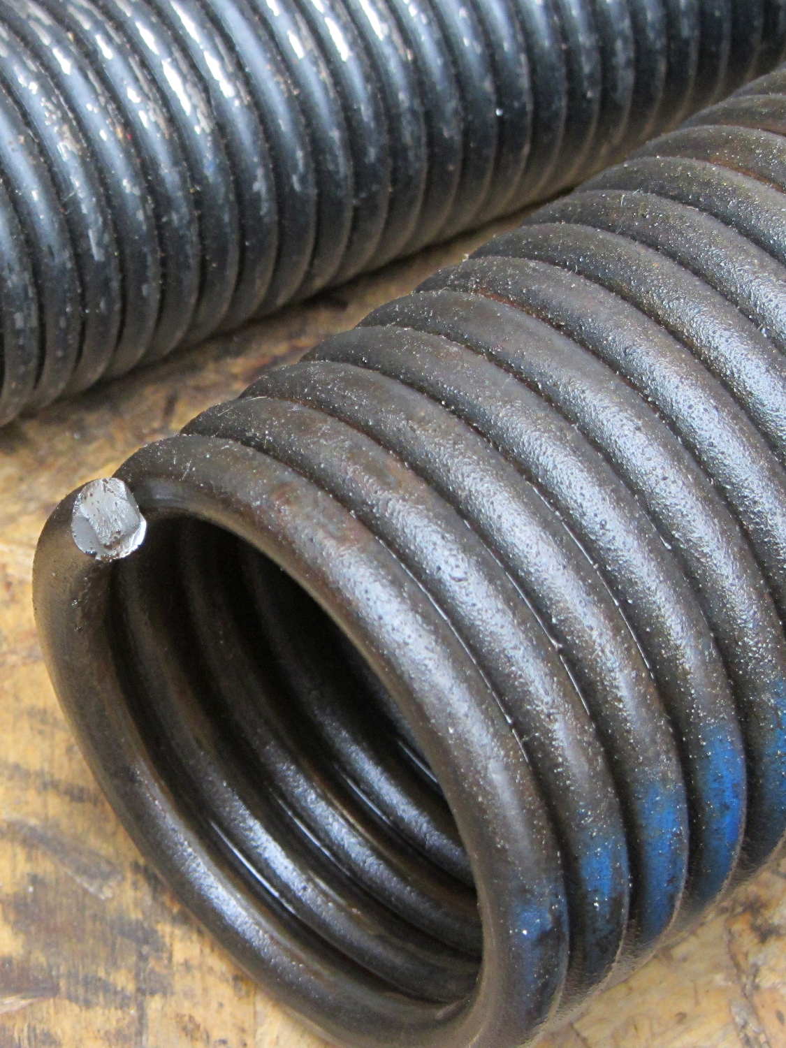
The really good thing about having torsion springs on the garage door is that when one breaks, not much happens:
Garage door torsion spring – broken end
We decided to spray money on the problem and make it go away; the Dutchess Overhead Doors tech was here the morning after I called: quicker than Amazon Prime and he works much faster than I can.
As nearly as I can tell from the checkbook (remember checkbooks?), an original (to us, anyway) spring broke shortly after we moved in. If so, that spring lasted nearly 17 years; at two open-shut cycles per day, let’s call it 12,000 cycles.
For the record, the springs are:
29 inches long
1-3/4 inch ID
0.250 wire
7 foot tall door
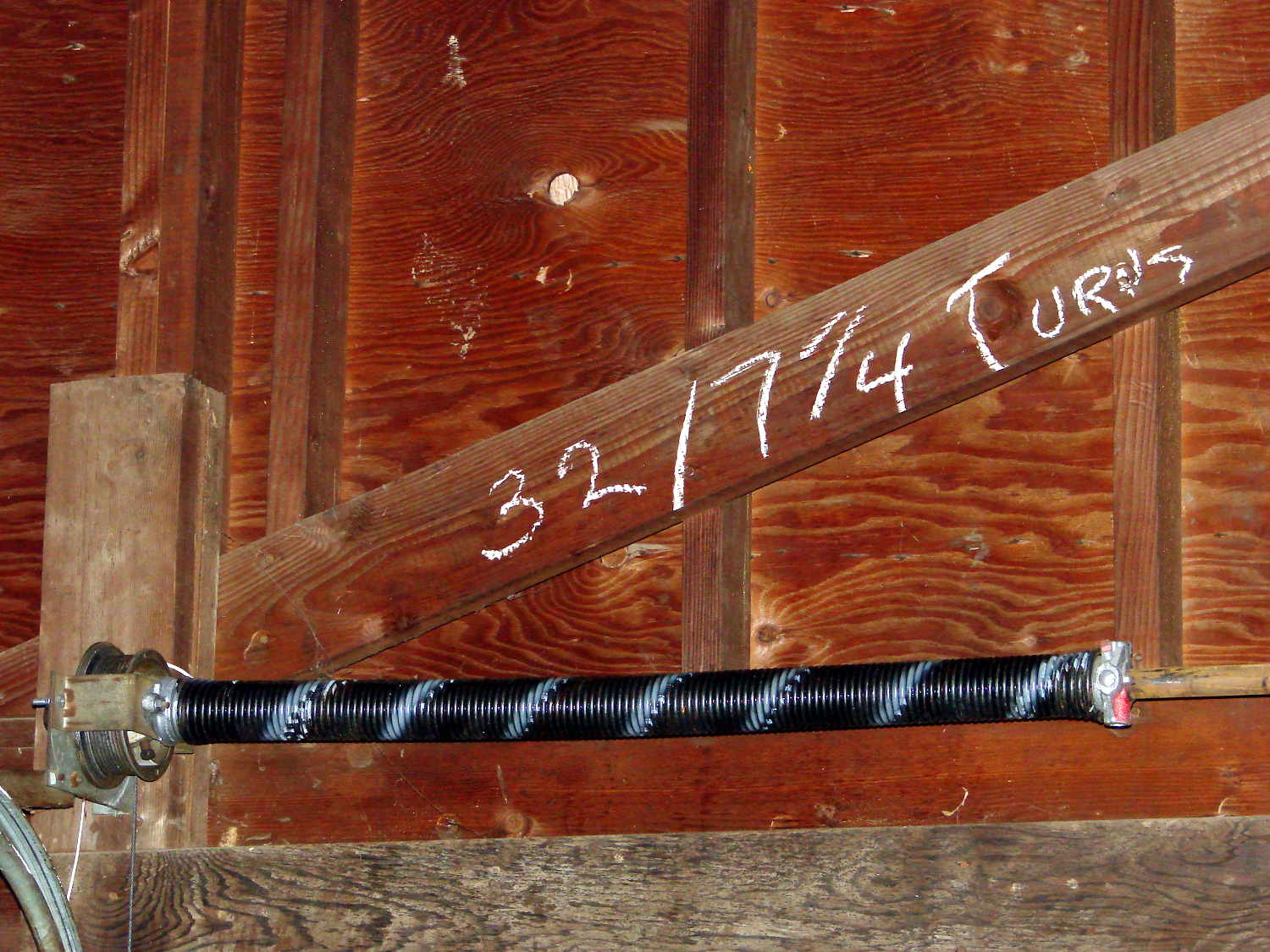
He cranked in seven full turns, corresponding to the “one turn per foot of door height” rule, although the door doesn’t quite balance on its own. I’d have done one more quarter-turn to match the chalk above the door (a good example of write it where you use it), plus maybe another for good measure, but I’m reluctant to mess with success:
Perhaps the 1955 springs were 32 inches long, but the tech replaced what he found both times. It’s a brute of a door, two generous cars wide, with plywood panels in heavy wood framing, plus a few pounds of filler I applied to the rather crazed surface before painting it some years ago.
I’m mildly surprised none of the dimensions changed in the last 60 years: the springs, end caps, pulleys, and hardware directly interchanged.
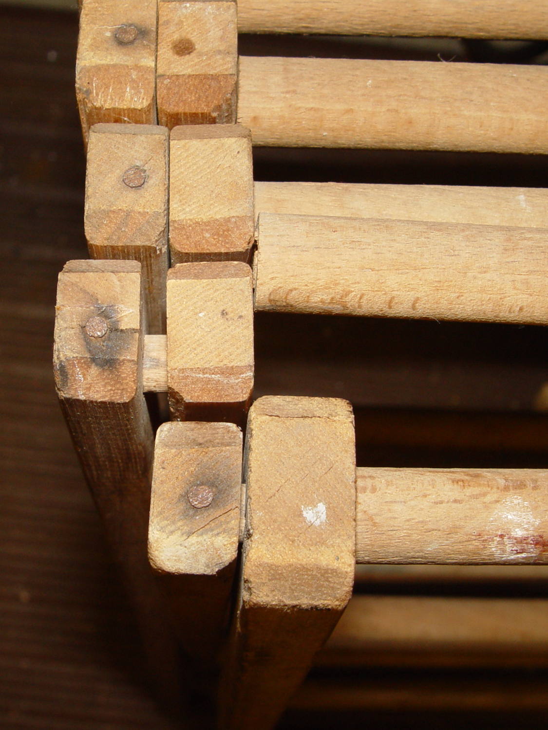
One of the rungs in the drying rack that keeps my bath towel from crawling away broke:
Drying Rack – broken rung
The rungs have turned-down pegs on the ends that slide through the inner side strut and anchor into the outer strut with a nail through the end. You can see the peg between the struts.
Removing the nail split the end of the strut, so I slobbered urethane glue into the crack and clamped it together overnight:
Drying Rack – strut gluing
Rather than removing the strut and doing it right, I gingerly freehanded a 3/8 inch hole into the end with a Forstner bit:
Drying Rack – drilled reinforced rung
Yes, that’s off-center, but it’s dead on the scar where the peg broke off. I have no idea how they could turn down a cylinder to get an eccentric peg on the end.
The black heatstink tubing reinforces the absurdly thin wood shell remaining around the hole. It’s probably not required, given that I’m about to fill the hole with a hardwood peg; nothing exceeds like excess.
Cut a suitable length from a nearby foam paint brush handle that just happens to be both hardwood and 3/8 inch in diameter, dab urethane glue in the holes (but not in the inner strut!), stuff peg through inner strut, seat in outer strut, stretch things enough to slide peg into rung, separate struts to avoid inadvertently pasting them together:
Drying Rack – reassembled
Took about fifteen minutes over the course of three days while the glue cured.
Done!
Those of long memory may recall a similar repair to the previous rack; we do, occasionally, toss things. I did, of course, add some of its dowels to the Long Things Stockpile.
The big bag o’ new-old-stock Inmac ball-point plotter pens had five different colors, so I popped a black ceramic tip pen in Slot 0 and ran off Yet Another Superformula Demo Plot:
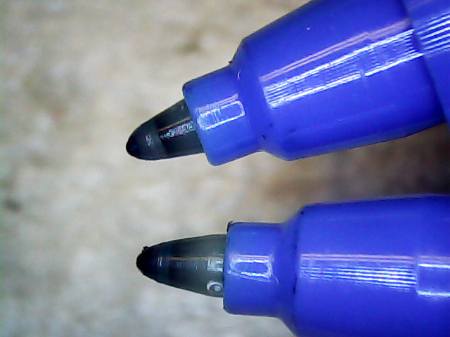
HP 7475A – Inmac ball pens – weak blue
All the ball pens produce spidery lines, but the blue pen seemed intermittent. Another blue pen from the bag behaved the same way, so I pulled the tip outward and tucked a wrap of fine copper wire underneath. You can see the wire peeking out at about 5 o’clock, with the end at 3-ish:
HP 7475A – Inmac ball pen – wire spacer
The wire holds the tip slightly further away from the locating flange and, presumably, makes it press slightly harder against the paper:
HP 7475A – Inmac ball pen – stock vs. extended
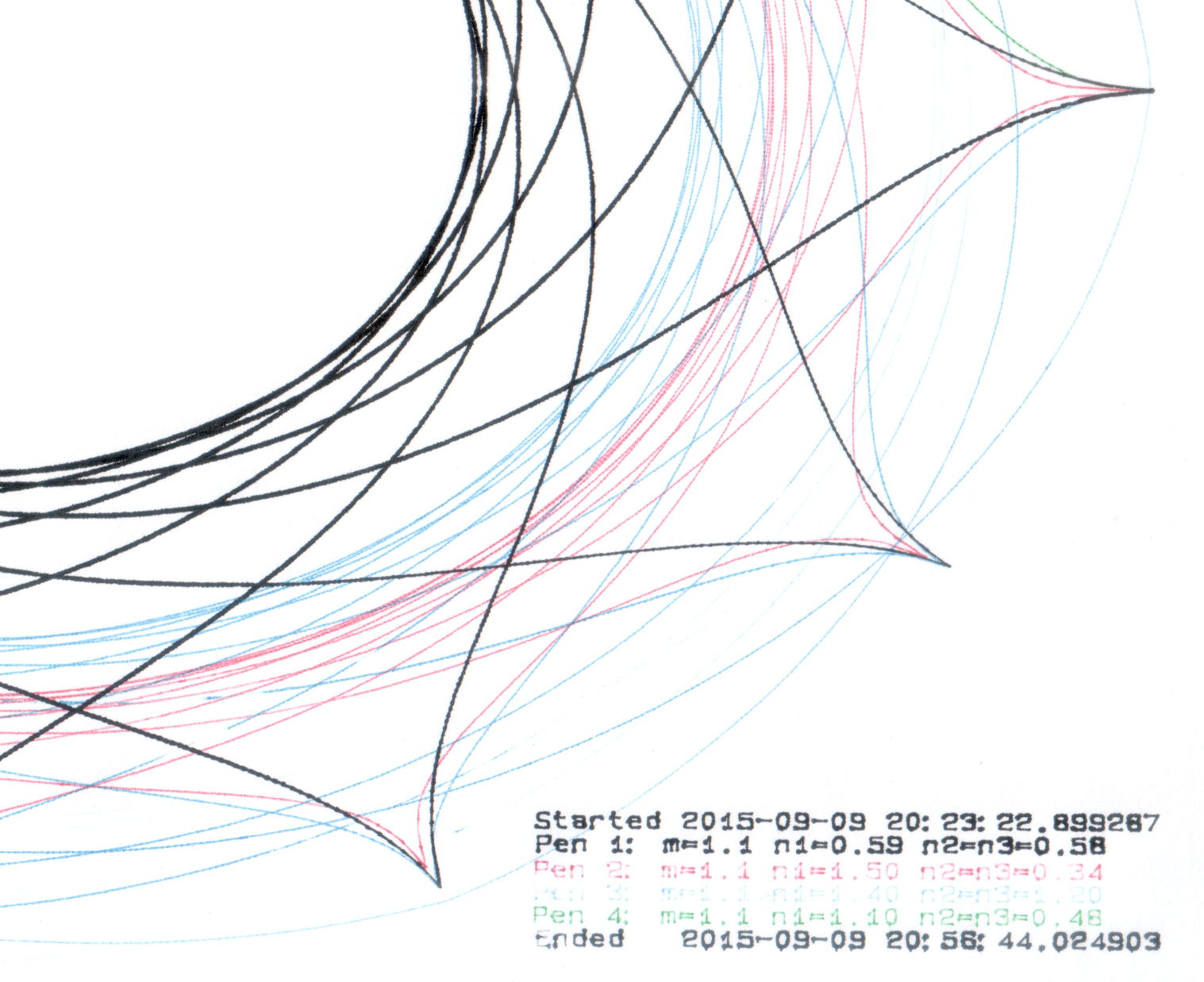
A bit more pressure helped, but not enough to make it dependable, particularly during startup on the legend characters:
HP 7475A – Inmac ball pens – extended blue
That black line comes from an ordinary fiber-tip pen that looks like a crayon on a paper towel by comparison with the hair-fine ball point lines.
Delicacy doesn’t count for much in these plots, so I’ll save the ball pens for special occasions. If, that is, I can think of any…
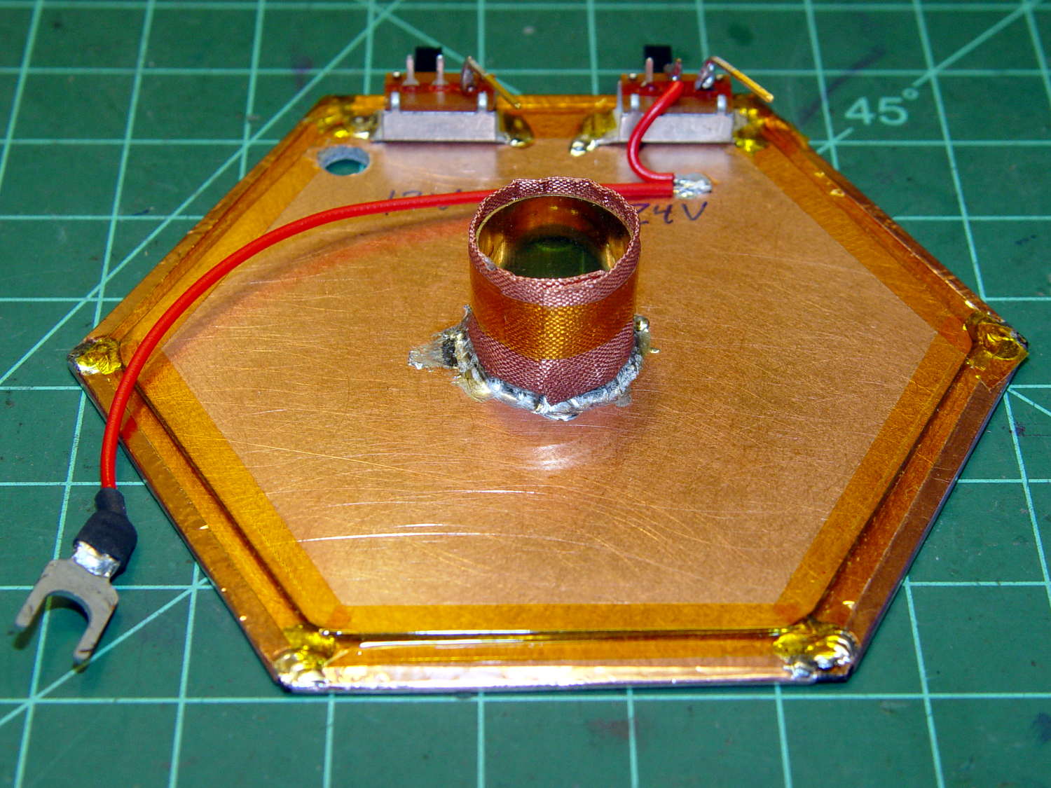
An undrilled double-sided circuit board with the edges bonded together doesn’t look like much:
Electrometer amp – undrilled shield planes
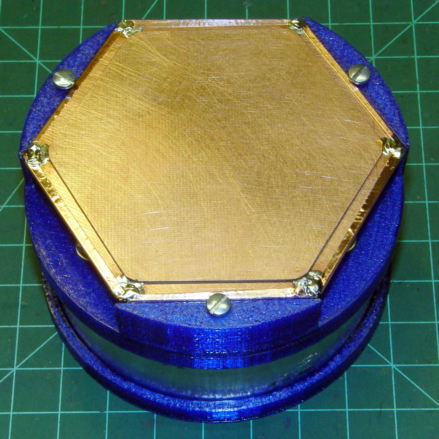
Soldering a smaller hex to the center of the bonded plate produces an isolated plane:
Electrometer amp – finished shield planes
The copper fabric tape wrapped around a brass tube soldered to the isolated plane contacts the ionization chamber shell around the central contact and (should) provide complete shielding. Kapton tape around the edges reduces the likelihood of inadvertent shorts.
Working with a shield at +24 V gave me the shakes, so this one confines the chamber bias to the isolated hex and shell, with the larger hex at circuit common (a.k.a. ground). The isolated plane has about 275 pF to the ground plane, which isn’t a Bad Thing at all. In principle, the chamber bias doesn’t need a switch, because there’s no current drain, but I vastly prefer having cold circuitry before popping the lid.
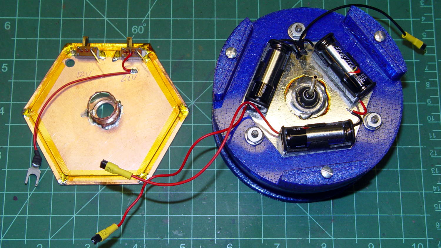
If I had a small DPST switch, I’d use it:
Electrometer amp – chamber – shield planes
As it stands, one switch controls the +24 V chamber bias and the other switches +12 V power to the electrometer amp front end, with simpleminded connectors so I can separate the pieces.
We’ll see how well all that works in practice.
An alert reader will notice the tiny difference between the blue PETG shapes in the two pictures. The bottom one comes from the revised code, of course.