Ed Nisley's Blog: Shop notes, electronics, firmware, machinery, 3D printing, laser cuttery, and curiosities. Contents: 100% human thinking, 0% AI slop.
The rail trail recently sprouted white mile markers:
Rail Trail – Marathon 13 mile marker
This one stood out:
Rail Trail – Marathon 13.10938 mile marker
Not being a marathoner, I had the vague notion a marathonshould be an even number of kilometers, because it’s not an even number of miles, but nooooo it’s just an arbitrary distance everybody agreed would be about right for a good long run.
During the rest of the ride, I worked out that 1 micro mile = 5+ milli foot = 60+ milli inch, so the rightmost significant figure in that marker represents increments of, oh, a smidge under ¾ inch. Middle of the hash line marks the spot, perhaps?
I’ve seen similar markers along other courses, with varying numbers of ahem significant figures, and will not say how long it took me to recognize what it represented.
The weather got warm enough to open the windows before pollen season started, which led to the front bathroom door slamming closed in the middle of the night when a gusty rainstorm blew through town. After far too many years, I decided this was an annoyance up with which I need no longer put.
A few minutes with OpenSCAD and Slic3r produces the shape:
Bathroom Door Retainer – Slic3r
It’s basically an extrusion of a 2D shape with a rectangular recess for the door chewed out.
An hour later, it’s in full effect:
Bathroom Door Retainer – installed
The model now sports a little ball to secure the retainer against the towel bar:
Bathroom Door Retainer – bump
Maybe someday I’ll reprint it.
That was easy …
The cast-iron pig sometimes standing guard as a doorstop in the relatively narrow doorway poses a bit of a foot hazard, so he moves into a closet during the off season. He can now remain there, snug and comfy, until a need for ballast arises.
This file contains hidden or bidirectional Unicode text that may be interpreted or compiled differently than what appears below. To review, open the file in an editor that reveals hidden Unicode characters.
Learn more about bidirectional Unicode characters
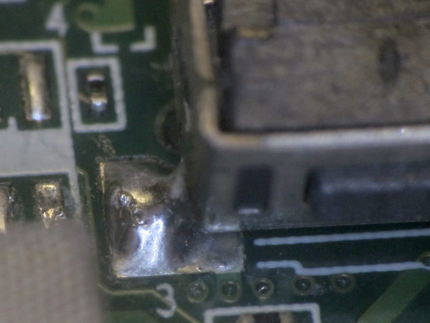
Once again, the single moving part on my first-generation Kindle Fire stopped working. As before, the switch contacts accumulated enough fuzz & contamination to prevent any current flow, but this time the (soft) solder joints attaching the switch body to the PCB failed:
Kindle Fire power switch – failed anchor
My joint cleaning & fluxing wasn’t up to contemporary standards, as shown by the obviously un-fused footprints left in the upper pads:
Kindle Fire power switch – failed anchor joints
The switch frame seems to be unplated steel, which shouldn’t be an excuse.
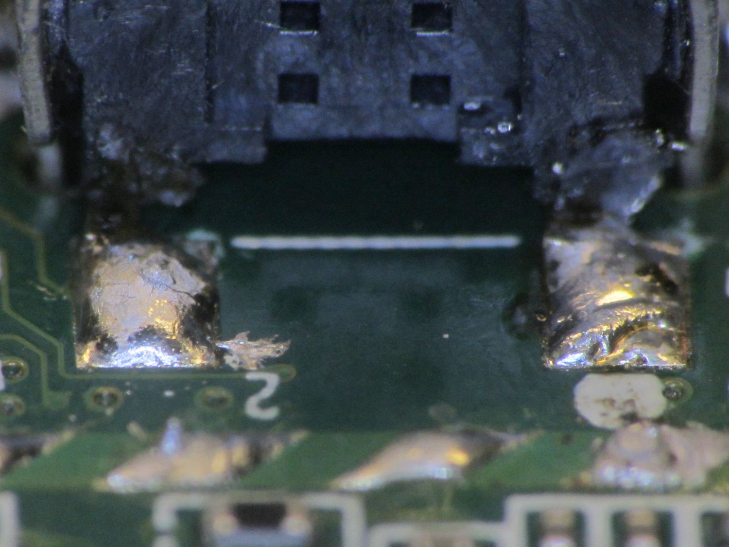
So I dismantled the switch, cleaned the contacts and tactile bump plate, put it all back together, and did a much better job of surface preparation:
Kindle Fire power switch – rebuilt – right anchor
The other joint:
Kindle Fire power switch – rebuilt – left anchor
And, for completeness, the switch leads:
Kindle Fire power switch – rebuilt – switch pads
I don’t like the way the joint on the right looks, either, but we’ll see how long the whole affair holds together.
This may be the last time I can repair the Kindle, as a bypass cap came loose while I was working on the PCB, the screen has been accumulating dust at an increasing pace, and several latches securing the back of the case have cracked.
Methinks it’s getting on time for a new pocketable memory device; if only Pixel XL phablets had a bigger screen and didn’t cost night onto a kilobuck.
The Zire would power on whenever the switches clicked or that little joystick moved, which happened regularly enough to be annoying.
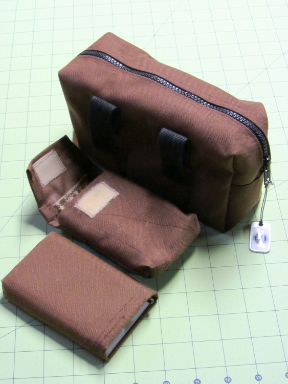
Mary made a small case that matched the other pouches I carry around:
Belt pack – camera case – PDA case
She made the case to fit an HP48 calculator, but it was close enough for the Zire.
Time passed, the Zire died, I started carrying a Kindle Fire in another pocket, but the ABS slab provided a convenient stiffener between some Geek Scratch Paper and the various pencils / pens / markers / screwdrivers / flashlight filling the available space.
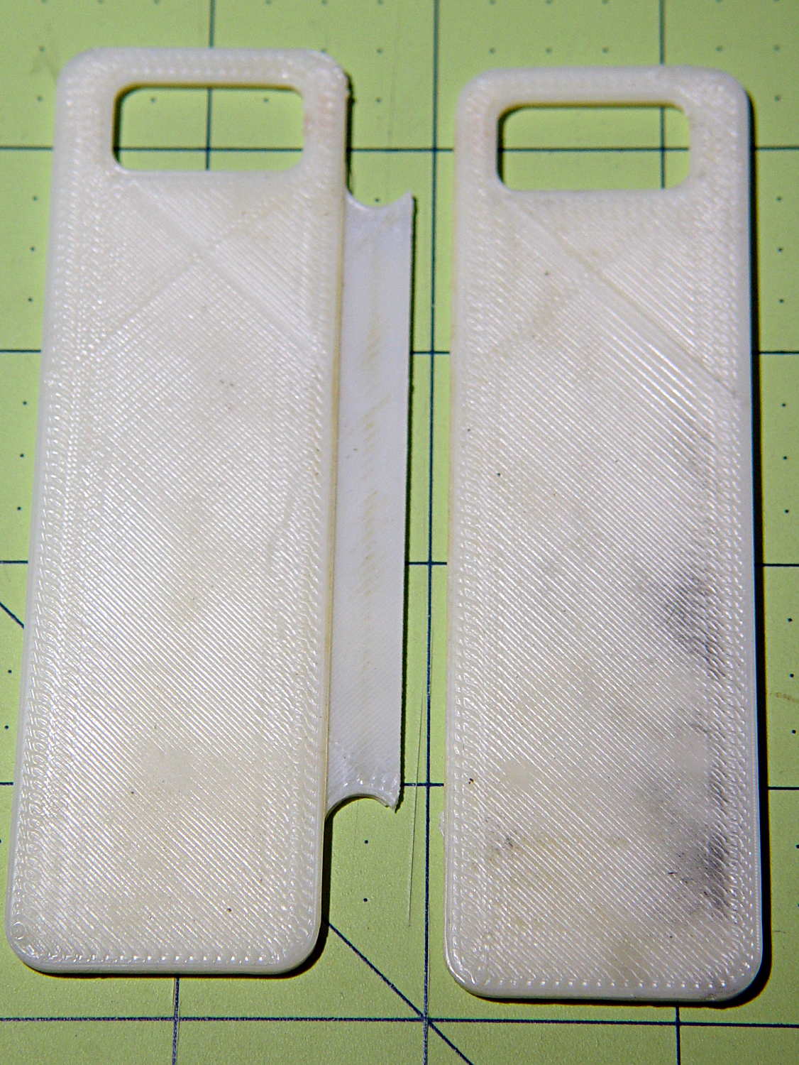
Unfortunately, minus the backup of an electronic slab, the protector finally failed along an obvious stress riser:
Zire 71 protector – cracked
I cut a similar rectangle from a sheet of unknown flexy plastic, rounded the corners, clipped the pencils & whatnot to it, and maybe it’ll survive for a while.
A quick-and-dirty test routine showed the sticks start out close to VCC/2:
Welcome to minicom 2.7

OPTIONS: I18n
Compiled on Feb  7 2016, 13:37:27.
Port /dev/ttyACM0, 10:23:45

Press CTRL-A Z for help on special keys

Joystick exercise
Ed Nisley - KE4ZNU - May 2017
00524 - 00513 - 1
That’s from minicom on the serial port, as the Arduino IDE’s built-in serial monitor ignores bare Carriage Return characters.
The joystick hat tilts ±25° from its spring-loaded center position, but the active region seems to cover only 15° of that arc, with a 5° dead zone around the center and 5° of overtravel at the limits. This is not a high-resolution instrument intended for fine motor control operations.
The analog input values range from 0x000 to 0x3FF across the active region. Aim the connector at your tummy to make the axes work the way you’d expect: left / down = minimum, right / up = maximum.
The delay(100) statements may or may not be needed for good analog input values, depending on some imponderables that seem not to apply for this lashup, but they pace the loop() to a reasonable update rate.
Pushing the hat toward the PCB activates the simple switch you can see in the picture. It requires an external pullup resistor (hence the INPUT_PULLUP configuration) and reports low = 0 when pressed.
Those are 0.125 inch (exactly!) holes on a 19.5×26.25 mm grid in a 26.5×34.25 mm PCB. Makes no sense to me, either.
This file contains hidden or bidirectional Unicode text that may be interpreted or compiled differently than what appears below. To review, open the file in an editor that reveals hidden Unicode characters.
Learn more about bidirectional Unicode characters
Having figured the mixing ratios, found the mixing trays, and donned my shop apron, I buttered up several iterations of the badge reel case to see how XTC-3D epoxy works on the little things around here.
In all cases, I haven’t done any sanding, buffing, or primping, mostly because I’m not that interested in the final surface finish.
A single coat produces a glossy finish with ripples from the printed threads:
XTC-3D – Hilbert – reflective
Seen straight on, without the glare, a little speck toward the lower right corner shows that cleanliness is next to impossible around here:
XTC-3D – lines – direct
An additional coat atop a Hilbert-curve upper surface comes out somewhat smoother:
XTC-3D – Hilbert – reflective 2
Another view, with less glare, shows the pattern a bit better:
XTC-3D – Hilbert – reflective 1
With no glare, the 3D Honeycomb infill shows through the surface:
XTC-3D – Hilbert – direct
Coating the surface with epoxy definitely makes it more transparent / less translucent by filling in the air gaps.
The sides of that part have only one coat and still show typical 3D printed striations.
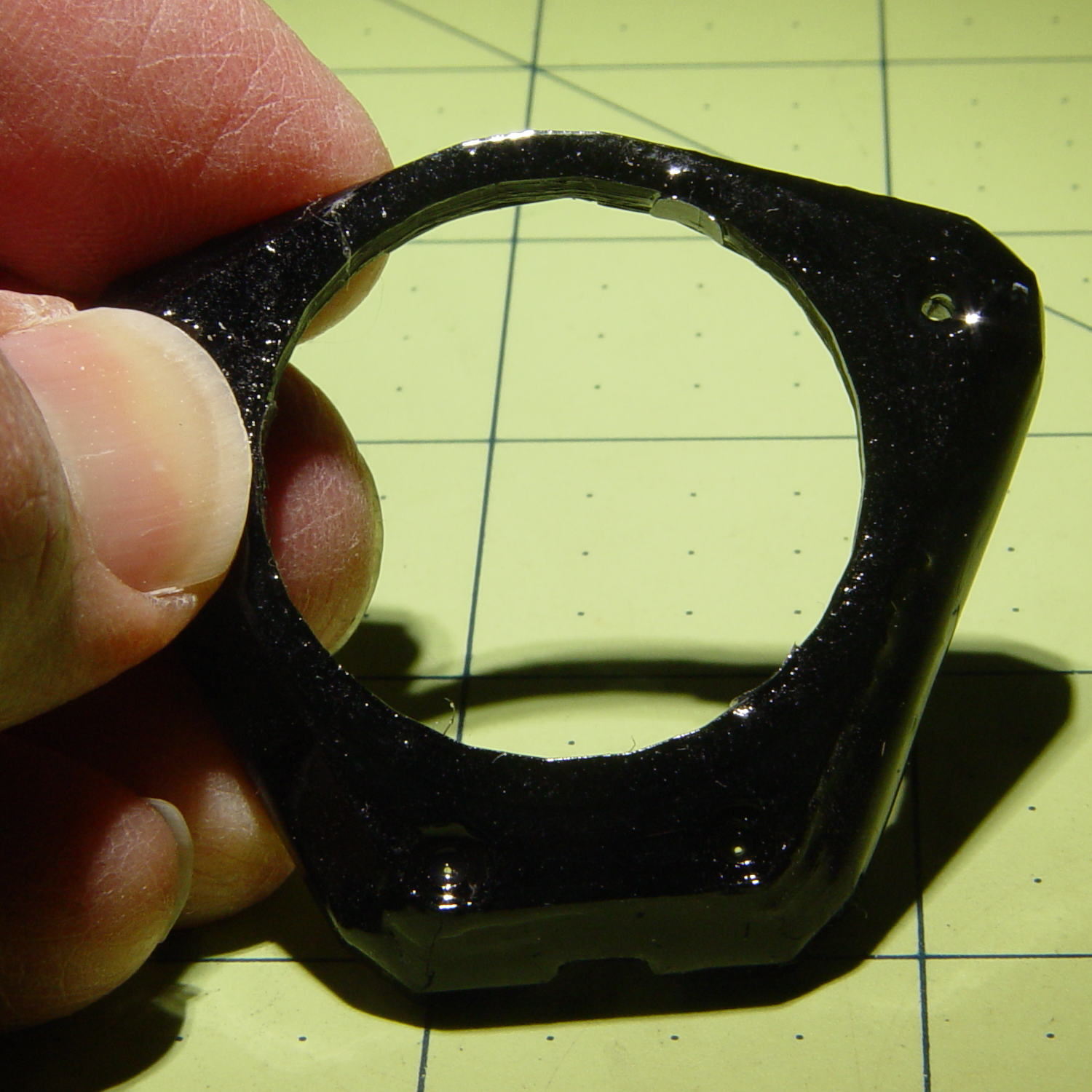
Three coats wipe out the striations, along with all other surface detail:
XTC-3D – Bezel – front oblique
The bolt head recesses collected enough epoxy to require reaming / milling, which certainly isn’t what you want in that situation. The bolt holes also shrank, although my usual hand-twisted drill would probably suffice to clear the epoxy.
Another view shows a glint from the smooth surface filling the upper-right recess:
XTC-3D – Bezel – front
Three coats definitely hides the 3D printed threads, although you can see some ridges and edges:
XTC-3D – heavy – oblique
The epoxy isn’t perfectly self-leveling, probably due to my (lack of) technique:
XTC-3D – heavy – reflection
Blowing out the contrast shows the surface finish:
XTC-3D – heavy – direct – boost
Those scratches come from fingernails, after the overnight curing time. The surface is hard, but not impervious to scratching, which is about what you’d expect for a clear epoxy.
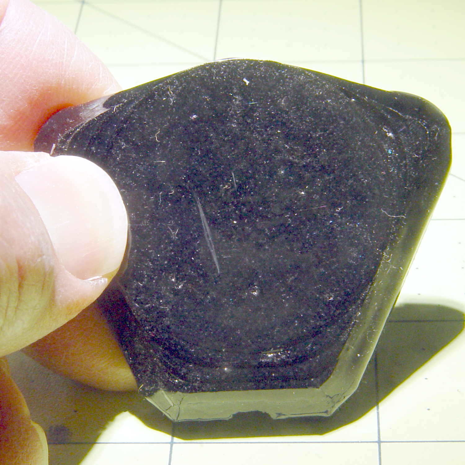
Slightly over-thinning the XTC-3D with denatured alcohol in a 0.7 : 0.3 : 0.3 by weight ratio produced a watery liquid that penetrated directly into the surface:
XTC-3D – thinned – oblique
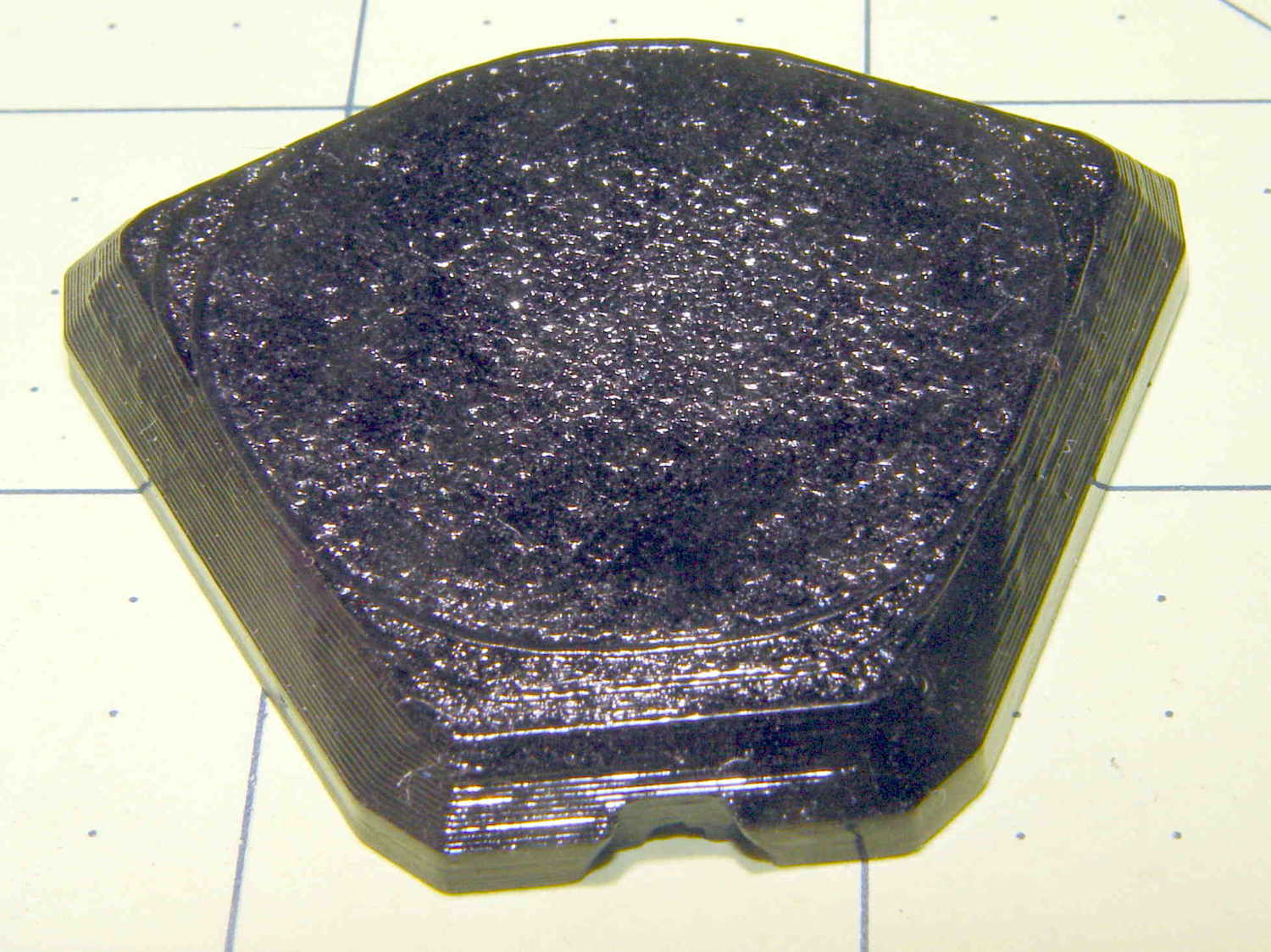
The finish depends critically on what’s below the surface and how much epoxy you apply. I tried to spread it uniformly with a foam brush, but the center came out somewhat rougher than the outer edge:
XTC-3D – thinned – oblique
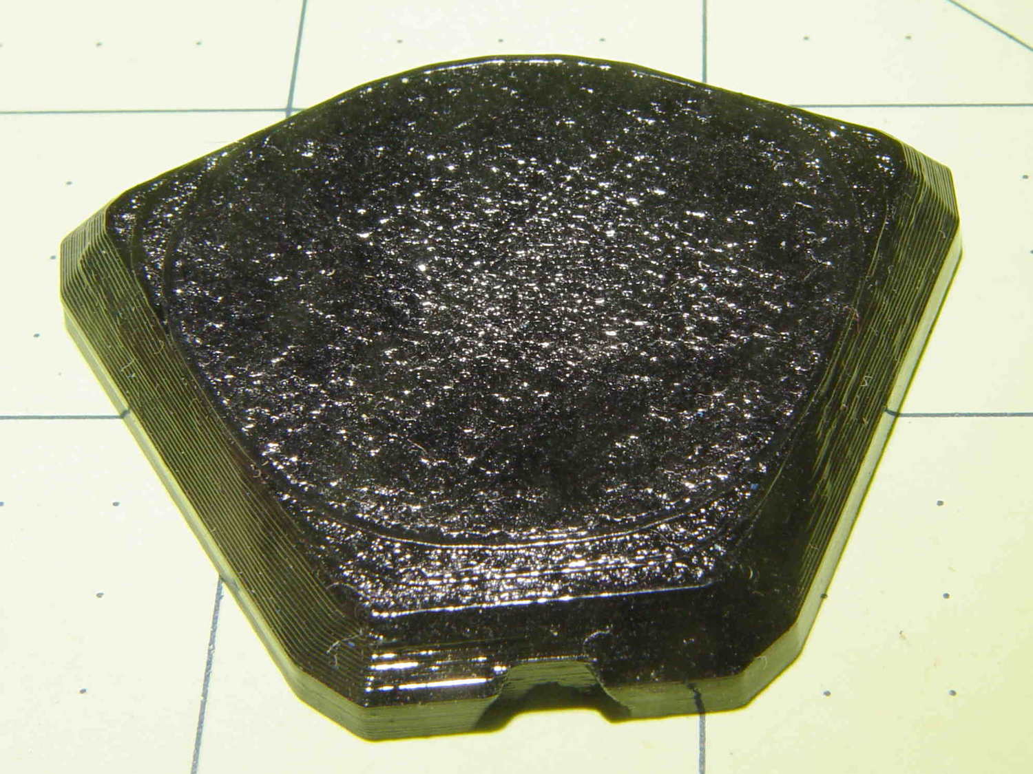
The striations along the sides filled in a bit, but surely not enough to satisfy anybody who worries about such things.
A specular reflection shows the changing surface smoothness:
XTC-3D – thinned – oblique reflective
Perhaps two coats of thinned epoxy would produce a watertight / airtight part, without changing the overall dimensions by very much. The mechanical properties depend almost entirely on the plastic-to-plastic bond, so I doubt a thin epoxy layer would improve its pressure-handling capabilities.
Few of the parts I make will benefit from an epoxy coating and I definitely don’t want to get into post-processing the parts just to improve their looks!
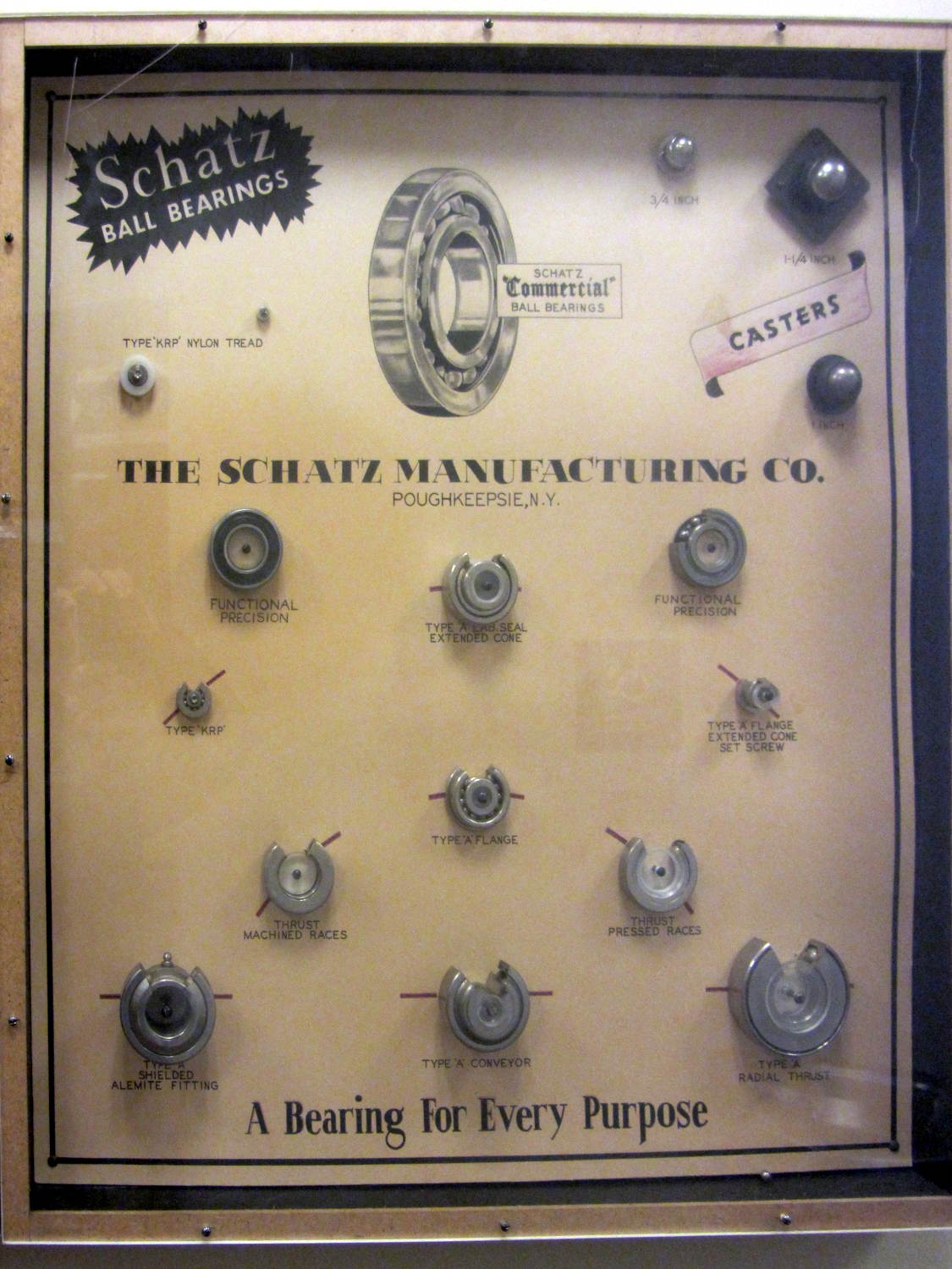
Schatz Manufacturing, a major bearing producer in Poughkeepsie, made a sample case to show off their wares:
Schatz Ball Bearings
You can tell by the yellowed backing paper that these have been around for a looong time.
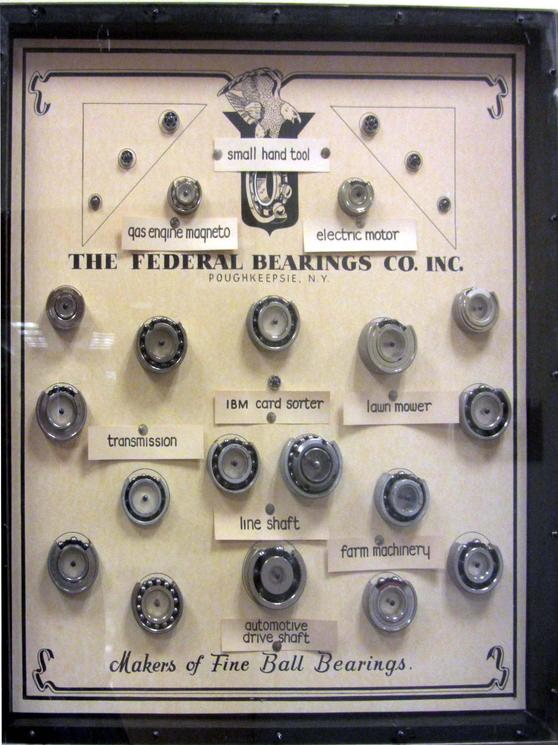
It turns out that Poughkeepsie had two bearing manufacturers. Federal Bearings went into the products of other locally important industries:
Federal Bearings
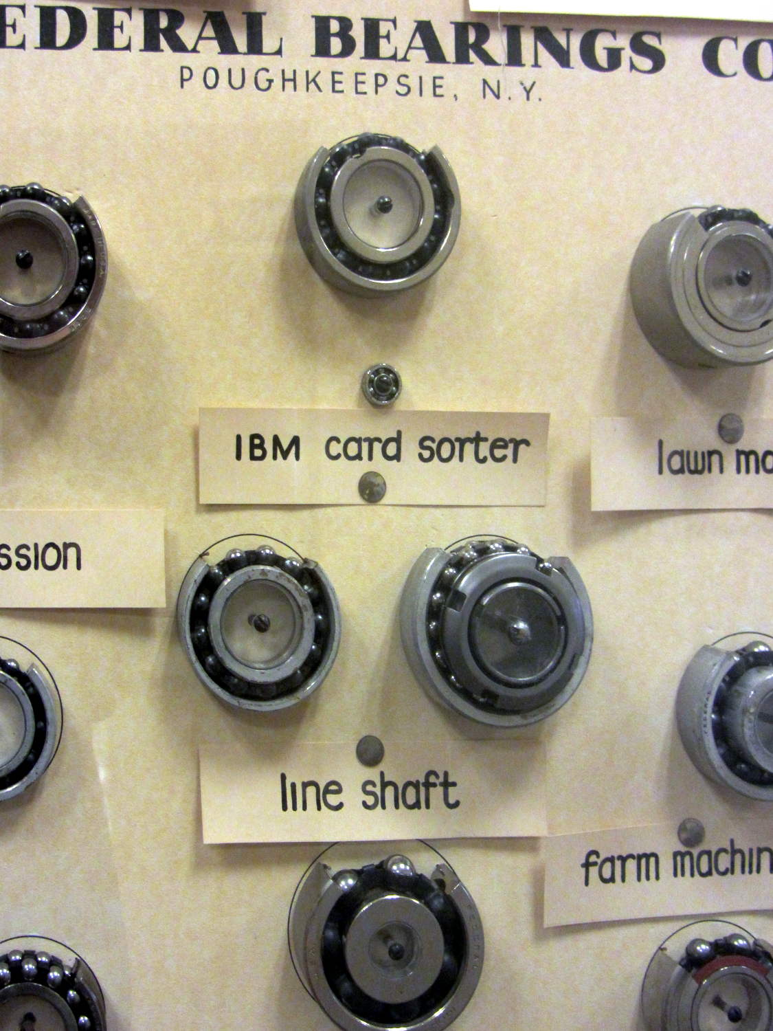
A detailed look shows what was important, back in the day:
Federal Bearings – Detail – IBM Card Sorter
Schatz and Federal later merged into Shatz Federal Bearings, eventually become Shatz Bearings, and still operate in Poughkeepsie. Some of their industrial waste remains here, too.
Out in the garage I still have a few grease pilots (*) from the final Schatz Federal downsizing / going-out-of-business / moving / whatever sale. A friend bought several sets of heavy-duty steel chests-of-drawers which contained, very much to his surprise, a huge assortment of grease pilots, ranging in size from fit-on-your-thumb to cover-a-dinner-plate, which he obviously had no use for. He unloaded them on me with a phrase that has lived on forevermore:
They’re a buck apiece, unless you take all of them, in which case they’re free.
You’ll find the sample cases on the top floor of Adriance Library, should you ever be in town.
Taken handheld in ambient light to avoid harsh flash shadows, then perspective-distorted to make them look like I was standing directly in front of the reflective plastic covers.
(*) Different from a “pilot bearing”. A “grease pilot” is a two-part circular steel assembly used to inject grease into the bearing races before snapping the shields in place. They’re painstakingly machined to cup the balls and fill the gaps, with a pipe fitting on the back surface for the grease pump.