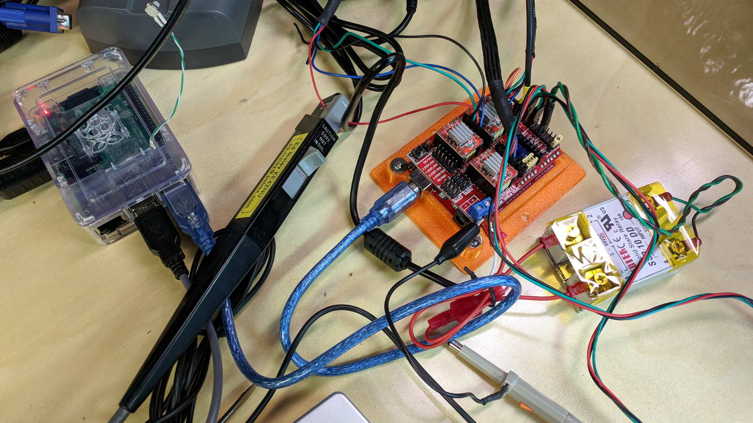
GRBL responds to critical errors by disabling its outputs, which seems like a useful feature for a big-enough-to-hurt CNC machine like the MPCNC. Unlike the RAMPS 1.4 board, there’s no dedicated power-control pin, so I connected the Coolant output to the same DC-DC SSR I tried out with the RAMPS board:

With homing enabled, GRBL emerges from power-on resets and error conditions with the spindle and coolant turned off and the G-Code interpreter in a locked state requiring manual intervention, so turning the stepper power on fits right in:
$x– Unlock the controlsm8– Coolant output on = enable stepper power$h– Home all axes
The steppers go clunk as the power supply turns on, providing an audible confirmation. The dim red LED on the SSR isn’t particularly conspicuous.
Turning the stepper power off:
m9– Coolant output off = disable stepper power
I think the A4988 drivers maintain their microstep position with the stepper power supply off, because their logic power remains on. In any event, you probably wouldn’t want to restart after an emergency stop without clearing the fault and re-homing the axes.
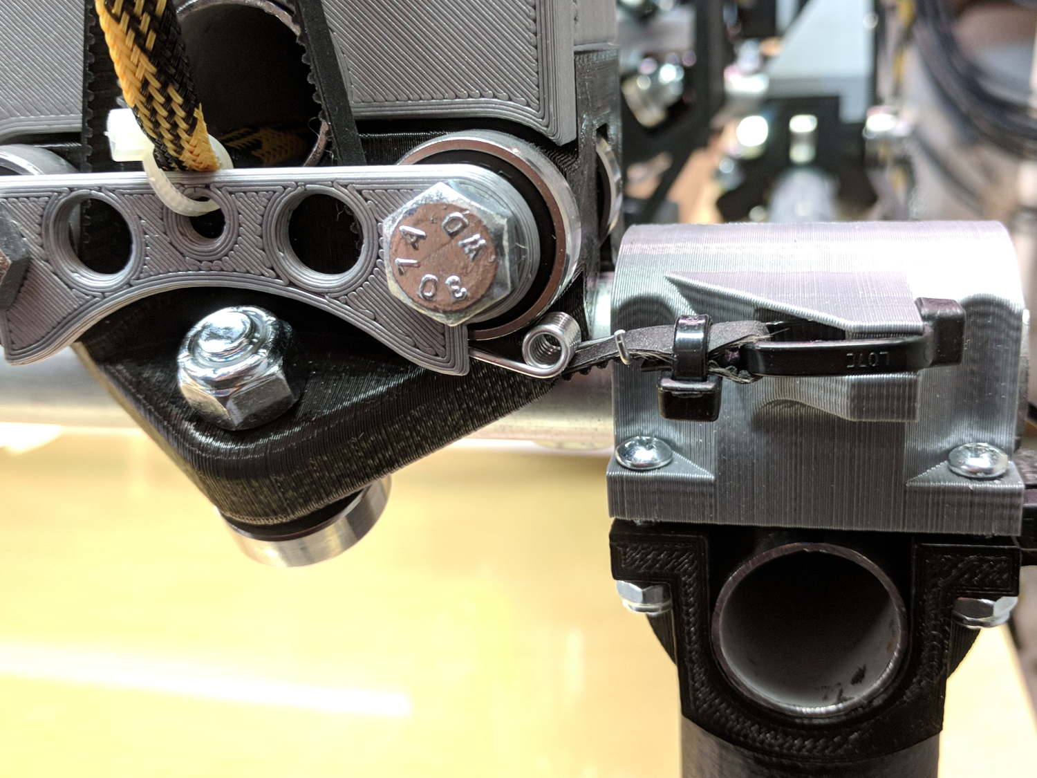
The board has Cycle Start, Feed Hold, and Abort inputs just crying out for big colorful pushbutton switches.
Unlike the RAMPS board, the Prontoneer CNC Shield does not feed stepper power to the underlying Arduino UNO, leaving it safely powered by USB or the coax jack.