One of the cold shoe mounts I made for the photo lamps cracked:
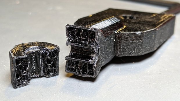
It’s done in PETG with my more-or-less standard two perimeter threads and 15% 3D honeycomb infill, which is Good Enough™ for most of my parts. In this case, there’s obviously not nearly enough plastic in there!
Redoing it with three perimeters and 50% infill should improve the situation, even though it looks identical on the outside:

I didn’t replace the other mount. If it breaks, it’ll get the same 50% infill as this one. If this one breaks, I’ll try 75%.
An easy fix!