Ed Nisley's Blog: Shop notes, electronics, firmware, machinery, 3D printing, laser cuttery, and curiosities. Contents: 100% human thinking, 0% AI slop.
An on-sale pack of yellow Astrobrights card stock tempted me:
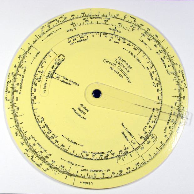
Homage Tek CC – Yellow Astrobrights paper
The somewhat wrecked cursor comes from my collection of discards, because I haven’t yet figured out how to mill the outline and engrave the hairline on raw stock.
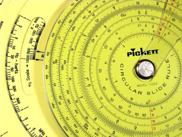
The paper isn’t quite the same color as my Genuine Pickett Model 110-ES circular slide rule:
Homage Tek CC vs Pickett 110ES colors
Nor, of course, are the ticks and legends nearly as fine as you get with real engraving, but it’s probably Close Enough™ for anybody other than a Real Collector™.
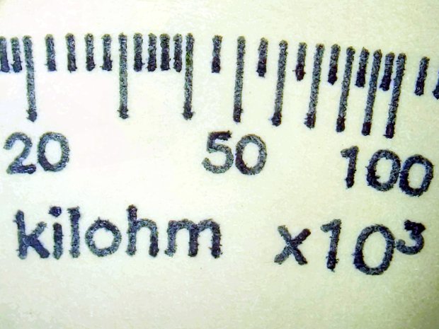
Two coats of black paint produced the larger areas along the inner scales and completely filled those engraved lines:
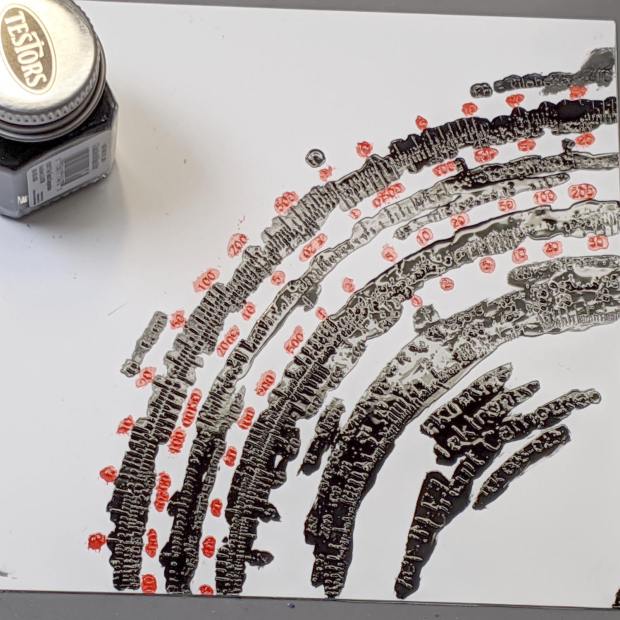
Engraving Testpiece D – Testors Enamel – red black applied
With exactly the correct paint on exactly the correct material, it cured into a non-removable layer. Being enamel, however, the last coat requires two or three days for a full cure, so this isn’t a short-attention-span project.
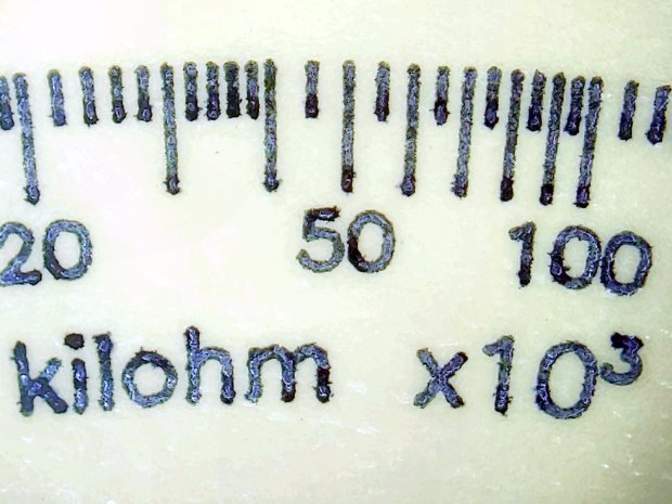
It’s “non-removable” unless you’re willing to abrade the surface:
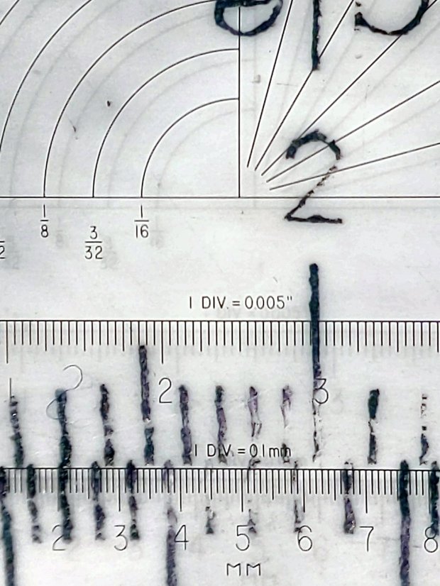
Sanding tends to remove too much plastic, particularly when confronted with raised walls & suchlike along the grooves. The darkest scale down the middle was engraved with 300 g downforce and is deep enough to retain all its paint:
Engraving Testpiece D – Testors Enamel – sanded – 250 300 g – detail
Engraving Testpiece D – Testors Enamel – scrape – 250 300 g – detail
There’s not much visible difference between the 250 g and 300 g scales.
All the scraped lines are over 0.1 mm wide, with the heavier downforce producing maybe 0.12 mm.
The double-coated lines are flush with the (scraped) surface and visibly matte. The single-coated regions have the usual glossy enamel finish remaining deep in the lines & numbers, with a thin matte outline flush with the surrounding surface. It’s basically impossible to photograph those features, at least for me.
The colors are crisp & vivid: enamel paint is the way to go!
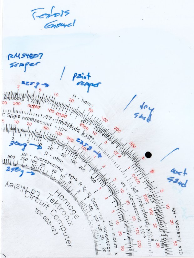
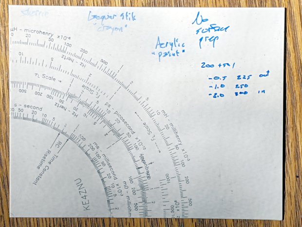
The next testpiece should run downforce variations from 300 through 500 g and speeds from 1000 to 2400 mm/min. Scraping off the raised plastic before painting should deliver a better ahem painting experience without much surface damage; the trick will be clearing all the debris from the engraved lines.
Diamond on styrene C – scraped red-black Sharpie – start
Instead of sanding the surface, I used a paint scraper to remove everything down to the engraved grooves. The scraper in the upper right is a Rubbermaid 54807, which is apparently no longer available. If I ever buy a new scraper, I’ll spring for a carbide blade.
A dirt speck under the plastic sheet can still obliterate the markings, though:
Diamond on styrene C – scraped red-black Sharpie – first clearing
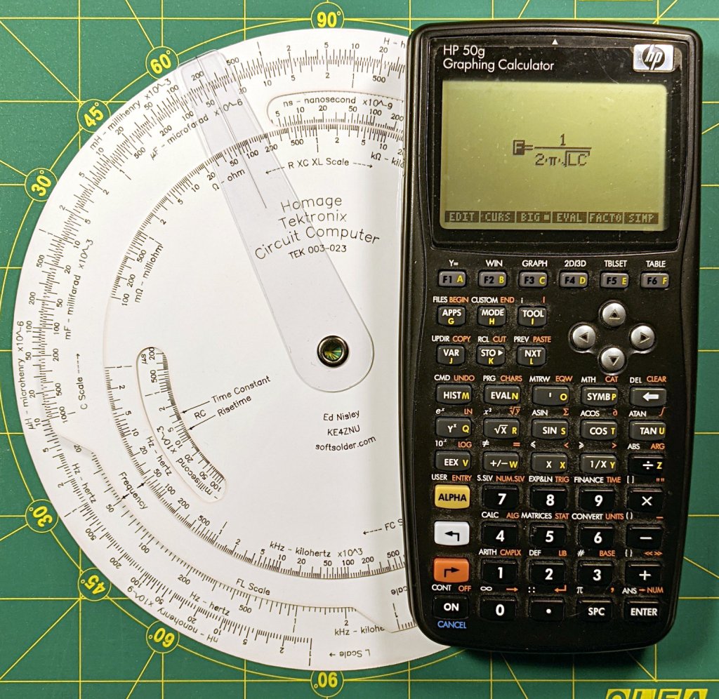
Overall, the results look just like a real slipstick:
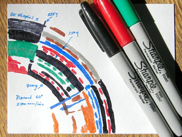
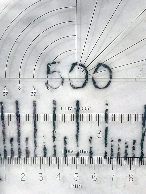
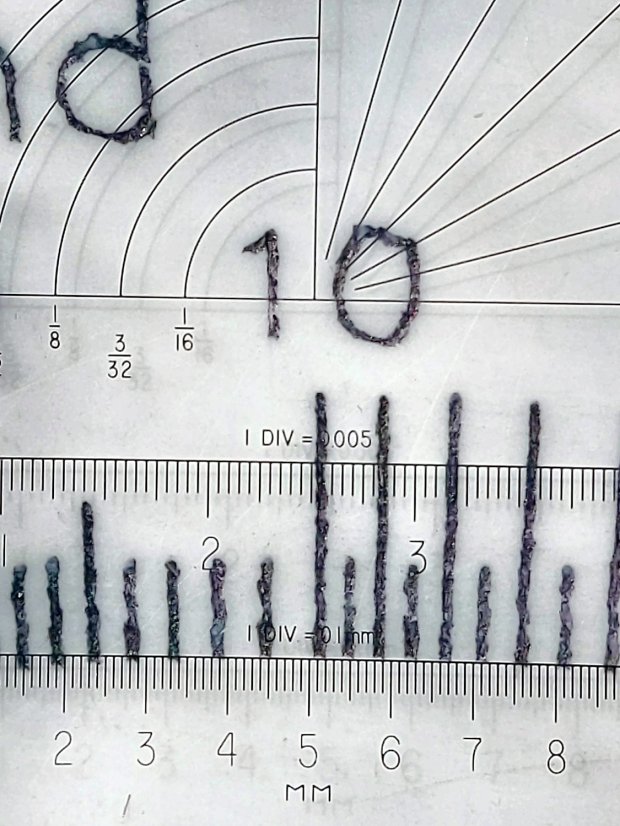
Diamond on styrene C – scraped red-black Sharpie – 225 300 g scale detail
The upper scale was engraved at 225 g downforce, the lower at 300 g, with corresponding differences in width & depth.
Diamond on styrene C – scraped red-black Sharpie – 225 300 g line detail
The upper ticks are 0.1 mm wide and the lower ticks a scant 0.2 mm wide. Both ticks on the sanded Sharpie sample were close to 0.1 mm, which suggests:
Scraping removes less plastic
The grooves have a flat-ish bottom and side walls roughly matching the slightly worn 60° diamond tool
Sharpie ink is, of course, soluble in alcohol:
Diamond on styrene C – scraped red-black Sharpie – alcohol wipe
That’s not unexpected, as I’ve been removing Sharpie with alcohol forever, but it’s worth keeping in mind. I don’t know if spraying a clear topcoat (Krylon FTW!) would provide good sealing with enough wear resistance.
The “300 g” notation is wrong: the innermost scale is on the middle deck, which I engraved with 250 g of downforce, and reads through a window on the top deck. The next scale outward, the inner half of the green block on the left, would be on the upper deck at 300 g, just beyond the innermost scale.
I removed the excess marker with a 320 (-ish) grit abrasive sanding block, producing a remarkable amount of gray dust in the process:
Diamond on styrene B – sanded
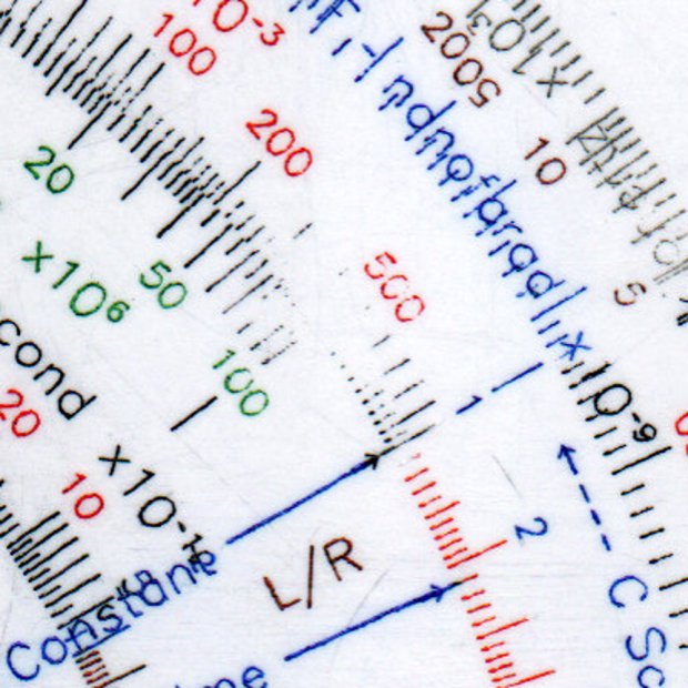
The general idea was to find out what the colors looked like when confined to narrow engraved slots:
Engraving Testpiece B – Sharpie colors – 2×600 dpi
It’s enlarged a factor of two from the 600 dpi scanned image by the simple expedient of changing it to 300 dpi, then assuming all the downstream image handling will Do The Right Thing, which could happen.
I sanded it before fully appreciating how even the smallest particle of crud under the styrene sheet ruins the result:
Engraving Testpiece B – debris oversanding
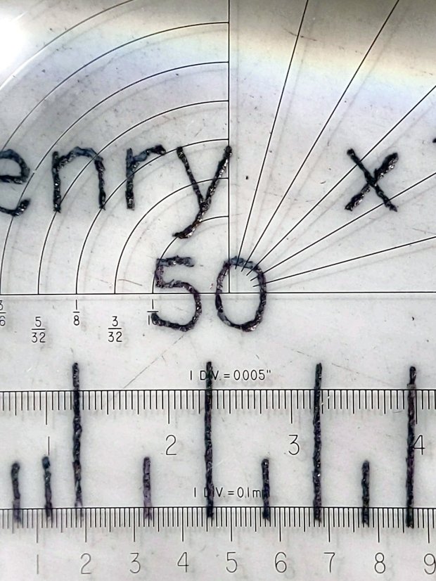
In this section, the scale with green numbers and black ticks was engraved at 300 g and is slightly less abraded than the adjacent scale at 225 g. Guesstimating the depth at 0.13 mm, 0.15 mm at most, the sanding block doesn’t remove much plastic at all … just enough to remove the scales.
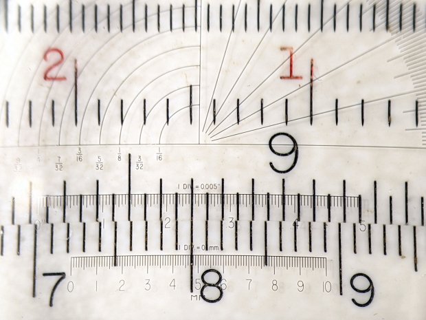
The lines are all about 0.1 mm wide and, to the naked eyeball, look about the same as the lines on my K&E Deci-Lon slipstick:, done on a real production line with an actual engraving tool and somebody who knew what he (I’m sure) was doing:
KE Deci-Lon Slide Rule – scale detail
The red CI scale reads right-to-left and, under magnification, you can see where the red ink made its way into the adjacent tick marks. I doubt they were using a pen, but it might be a mechanized roller or dauber.
All in all, sanding works, but it’s messy and poorly controlled.
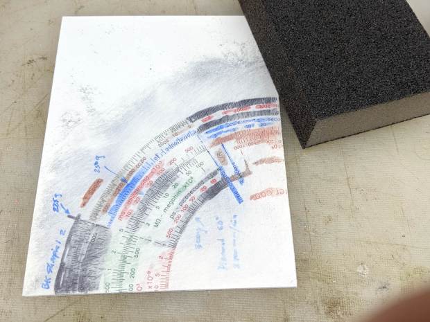
I covered one quarter with good old black Sharpie, a lacquer crayon, and well-aged black acrylic wall paint:
Diamond on styrene – engraving test – raw color fill
Applying a sanding block removed the rubble + scribbles and brought the surface down to the engraved patterns:
Diamond on styrene – engraving test – 225 250 300g 2400mm-min
The lacquer crayon doesn’t seem to adhere well to styrene:
Diamond on styrene – 225 250 g 2400mm-min – lacquer crayon
A closer look shows I probably sanded off too much of the surface, perhaps above some grit below the sheet, because those lines almost vanish:
Diamond on styrene – 225 250 g 2400mm-min – lacquer crayon
The crayon may adhere better to deeper lines. These are obviously too shallow and the pigment seems to come off in chunks:
Diamond on styrene – 300g 2400mm-min – lacquer crayon
The acrylic trim paint filled its patterns, despite having turned into a gummy mass during decades on the shelf:
Diamond on styrene – 225g 2400mm-min – acrylic paint
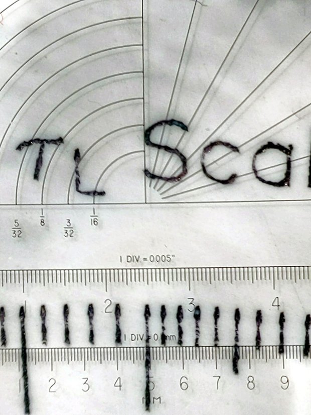
The Sharpie ink, being basically a thin liquid, completely filled its patterns and (apparently) soaked into the rough side walls. The lines seem to be 0.1 mm wide at 225 g downforce:
Diamond on styrene – 225g 2400mm-min – Sharpie
They’re less uniform at 250 g:
Diamond on styrene – 250g 2400mm-min – Sharpie
A 300 g downforce produces (somewhat) more uniform 0.15 mm wide lines and slightly distorted characters:
Diamond on styrene – 300g 2400mm-min – Sharpie
I have no way to measure the actual engraving depth. If the 60° diamond tool had a perfect point, which it definitely doesn’t, then a 0.15 mm wide trench would be 0.13 mm deep. I’ve obviously sanded off some of the surface, so those lines could be, at most, 0.1 mm deep.
All in all, the engraving came out better than I expected!
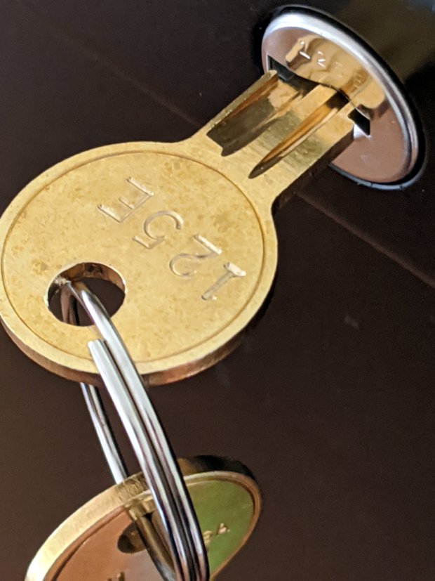
You’d hope the original owner would tape a key inside each file cabinet before donating it to charity; ours arrived unlocked and without keys. Fortunately, eBay sellers have All The Keys and I ordered replacement keys for each cabinet.
One pair of new keys fit into their lock, but the shoulder didn’t seat properly and the key didn’t turn:
HON Lateral File – 125E key insertion
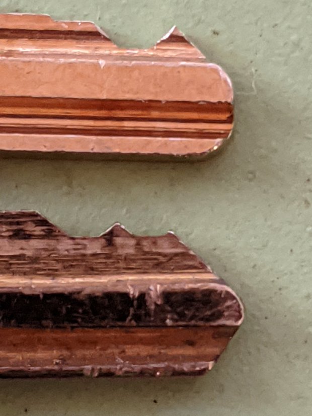
Compared with a key for the other cabinet (on the bottom), it seems the tip profile wasn’t quite the same:
HON Lateral File – 125E key tip
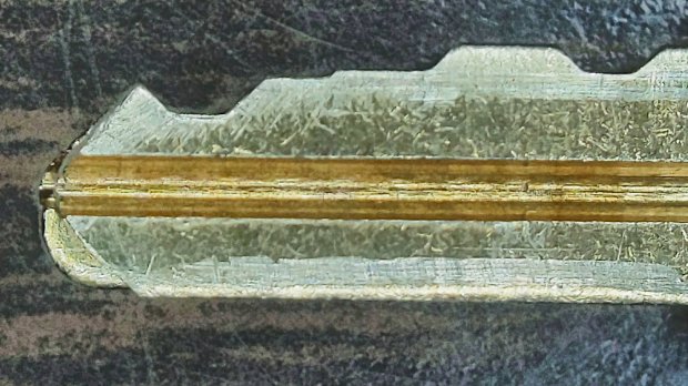
Perhaps the underside of the tip hadn’t been cut? Stacking the two keys makes it even more obvious:
Key 125E tip shaping – vs Key 101E
The eBay seller suggested the lock cores have changed over the years, as other (unaltered) keys fit current cabinet locks. Perhaps HON used fussy high-quality lock cores back in 2004 when they built these cabinets.
I gingerly filed the 125E key’s tip to match the 101E key and, after several iterations, the shoulder seated firmly in the lock and the core turned smoothly. Flushed with success, I marked the other key of the pair, filed to the mark, and it worked on the first try.
Mary doesn’t plan to store any secret fabrics in her new cabinets, but now I can declare victory and move on.