The Smell of Molten Projects in the Morning

Ed Nisley's Blog: Shop notes, electronics, firmware, machinery, 3D printing, laser cuttery, and curiosities. Contents: 100% human thinking, 0% AI slop.

Category: Machine Shop

Mechanical widgetry

  • Improved Mini-lathe Disk Turning Fixture

    Improved Mini-lathe Disk Turning Fixture

    Unsurprisingly, the mini-lathe lacks enough stiffness to apply enough force to hold a disk in place while turning its rim:

    Tour Easy Rear Running Light - end cap fixture - swirled adhesive
    Tour Easy Rear Running Light – end cap fixture – swirled adhesive

    The old South Bend lathe had mojo, but those days are gone.

    So drill and tap that fixture for an M3 screw, then stick some coarse sandpaper to it:

    Improved disk turning tool
    Improved disk turning tool

    Snug the screw (a Torx T9 from the Small Drawer o’ Random M3 Screws) down on a rough-cut disk:

    Improved disk turning tool - in use
    Improved disk turning tool – in use

    Sissy cuts remain the order of the day, but the screw applies plenty of clamping force and doesn’t require the hulking live center.

  • Tube Turning Adapters

    Tube Turning Adapters

    Finishing the PVC tubes reinforcing the vacuum cleaner adapters required fixtures on each end:

    Dirt Devil adapter - pipe turning
    Dirt Devil adapter – pipe turning

    Because the tubes get epoxied into the adapters, there’s no particular need for a smooth surface finish and, in fact, some surface roughness makes for a good epoxy bond. The interior of a 3D printed adapter is nothing if not rough; the epoxy in between will be perfectly happy.

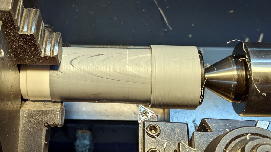
    Turning the tubes started by just grabbing the conduit in the chuck and peeling the end that stuck out down to the finished diameter, because the conduit was thick-walled enough to let that work.

    The remaining wall was so thin that the chuck would crunch it into a three-lobed shape, so the white ring in the chuck is a scrap of PVC pipe turned to fit the tube ID and provide enough reinforcement to keep the tube round.

    The conduit ID isn’t a controlled dimension and was, in point of fact, not particularly round. It was, however, smooth, which counts for more than anything inside a tube carrying airborne fuzzy debris; polishing the interior of a lathe-bored pipe simply wasn’t going to happen.

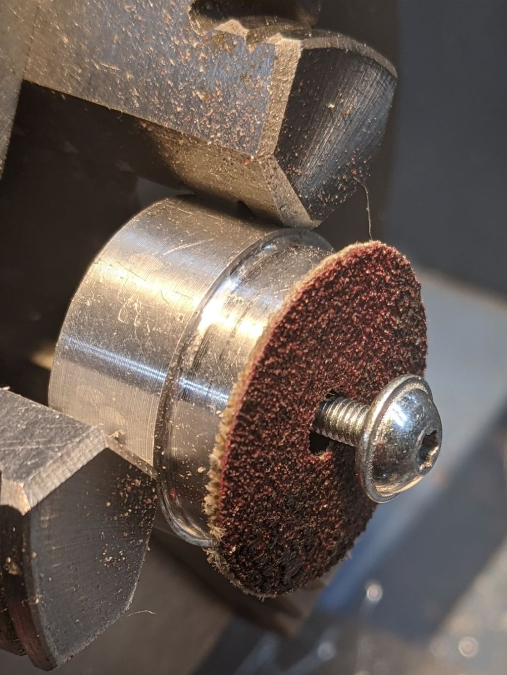
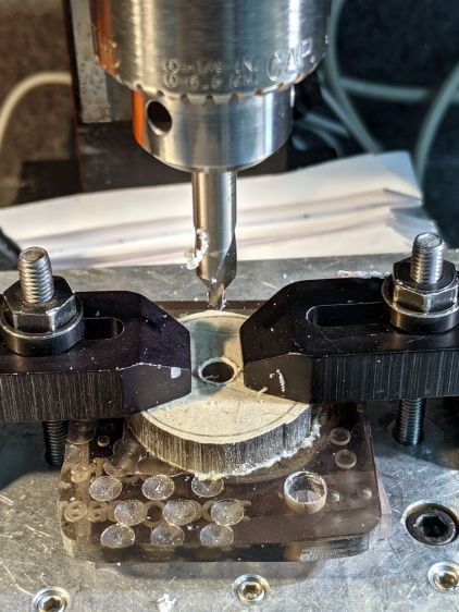
    The fixture on the other end started as a scrap of polycarbonate bandsawed into a disk with a hole center-drilled in the middle:

    Pipe end lathe fixture - center drilling
    Pipe end lathe fixture – center drilling

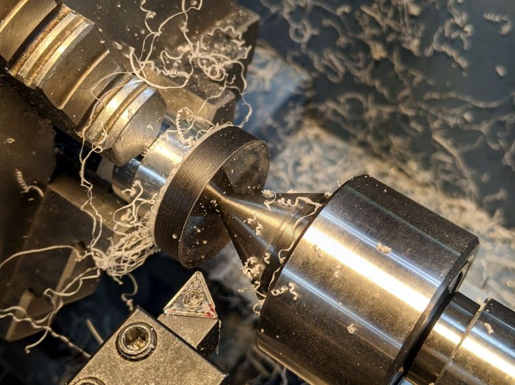
    Stick it onto a disk turning fixture and sissy-cut the OD down a little smaller than the eventual tube OD:

    Pipe end lathe fixture - turning OD
    Pipe end lathe fixture – turning OD

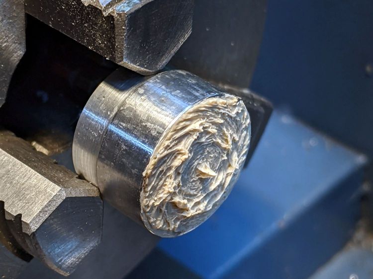
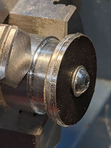
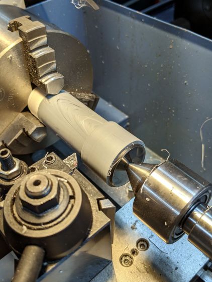
    Turn the end down to fit the tube ID, flip it around to center-drill the other side, stick it into the tube, and finally finish the job:

    Dirt Devil adapter - pipe fixture
    Dirt Devil adapter – pipe fixture

    The nice layering effect along the tube probably comes from molding the conduit from recycled PVC with no particular concern for color matching.

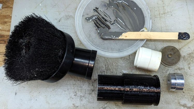
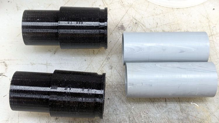
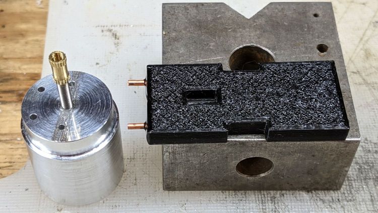
    A family portrait of the fixtures with a finished adapter:

    Dirt Devil adapter - fixtures
    Dirt Devil adapter – fixtures

    A fine chunk of Quality Shop Time: solid modeling, 3D printing, mini-lathe turning, and even some coordinate drilling on the Sherline.

  • Dirt Devil Vacuum Tool Adapters

    Dirt Devil Vacuum Tool Adapters

    Being the domain expert for adapters between a new vacuum cleaner and old tools, this made sense (even though it’s not our vacuum):

    Dirt Devil Nozzle Bushing - solid model
    Dirt Devil Nozzle Bushing – solid model

    The notch snaps into a Dirt Devil Power Stick vacuum cleaner and the tapered end fits a variety of old tools for other vacuum cleaners:

    Dirt Devil Nozzle Bushing top view - solid model
    Dirt Devil Nozzle Bushing top view – solid model

    Having some experience breaking thin-walled adapters, these have reinforcement from a PVC tube:

    Dirt Devil adapter - parts
    Dirt Devil adapter – parts

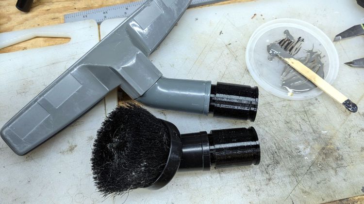
    A smear of epoxy around the interior holds the tube in place:

    Dirt Devil adapters - assembled
    Dirt Devil adapters – assembled

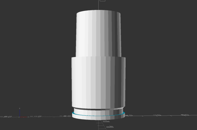
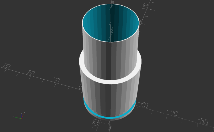
    Building the critical dimensions with a 3D printed part simplified the project, because I could (and did!) tweak the OpenSCAD code to match the tapers to the tools. Turning four of those tubes from a chunk of PVC conduit, however, makes a story for another day.

    The OpenSCAD source code as a GitHub Gist:

    // Dirt Devil nozzle adapter
    // Ed Nisley KE4ZNU 2021-10
    // Tool taper shift
    Finesse = -0.1; // [-0.5:0.1:0.5]
    // PVC pipe liner
    PipeOD = 28.5;
    /* [Hidden] */
    //- Extrusion parameters
    ThreadThick = 0.25;
    ThreadWidth = 0.40;
    HoleWindage = 0.2;
    function IntegerMultiple(Size,Unit) = Unit * ceil(Size / Unit);
    Protrusion = 0.1; // make holes end cleanly
    //———————-
    // Dimensions
    TAPER_MIN = 0;
    TAPER_MAX = 1;
    TAPER_LENGTH = 2;
    Socket = [36.0,37.0,40.0];
    LockringDia = 33.5;
    LockringWidth = 4.5;
    LockringOffset = 2.5;
    Tool = [Finesse,Finesse,0] + [30.0,31.1,30.0];
    AdapterOAL = Socket[TAPER_LENGTH] + Tool[TAPER_LENGTH];
    NumSides = 36;
    $fn = NumSides;
    //———————-
    // Useful routines
    module PolyCyl(Dia,Height,ForceSides=0) { // based on nophead's polyholes
    Sides = (ForceSides != 0) ? ForceSides : (ceil(Dia) + 2);
    FixDia = Dia / cos(180/Sides);
    cylinder(r=(FixDia + HoleWindage)/2,h=Height,$fn=Sides);
    }
    //——————-
    // Define it!
    module Adapter() {
    difference() {
    union() {
    difference() {
    cylinder(d1=Socket[TAPER_MIN],d2=Socket[TAPER_MAX],h=Socket[TAPER_LENGTH]);
    translate([0,0,LockringOffset])
    cylinder(d=2*Socket[TAPER_MAX],h=LockringWidth);
    }
    cylinder(d=LockringDia,h=Socket[TAPER_LENGTH]);
    translate([0,0,LockringOffset + 0.75*LockringWidth])
    cylinder(d1=LockringDia,d2=Socket[TAPER_MIN],h=0.25*LockringWidth);
    translate([0,0,Socket[TAPER_LENGTH]])
    cylinder(d1=Tool[TAPER_MAX],d2=Tool[TAPER_MIN],h=Tool[TAPER_LENGTH]);
    }
    translate([0,0,-Protrusion])
    PolyCyl(PipeOD,AdapterOAL + 2*Protrusion,NumSides);
    }
    }
    //———————-
    // Build it!
    Adapter();

    The taper in the code almost certainly won’t fit whatever tool you have: measure thrice, print twice, and maybe fit once …

  • Bondhus Wrench Replacement

    Bondhus Wrench Replacement

    The Bondhus Lifetime Guarantee works, as a replacement wrench just arrived:

    Bondhus hex wrenches - 7-64 ball end - replacement
    Bondhus hex wrenches – 7-64 ball end – replacement

    A close look at the aligned tips suggests the defective wrench blank was mis-chucked in the machine cutting the ball end:

    Bondhus hex wrenches - 7-64 ball end - replacement - detail
    Bondhus hex wrenches – 7-64 ball end – replacement – detail

    All’s well that ends well: thank you, Bondhus!

  • Micro-Mark Bandsaw: Acetal Upper Blade Guide

    Micro-Mark Bandsaw: Acetal Upper Blade Guide

    There being nothing like a good new problem to take one’s mind off all one’s old problems:

    Micro-Mark Bandsaw - acetal upper blade guide installed
    Micro-Mark Bandsaw – acetal upper blade guide installed

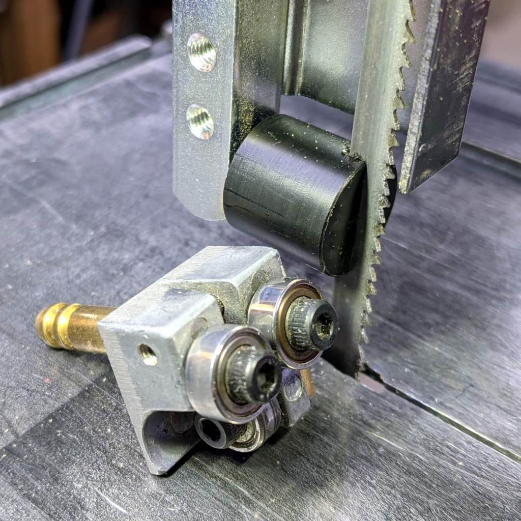
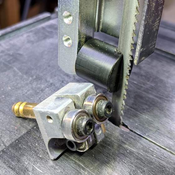
    It’s basically the same as the lower blade guide, except coming from a stick of 5/8 inch acetal. A scant 6 mm stem goes into the vertical square rod, with a flat matching the setscrew coming up from the bottom to hold it in proper alignment.

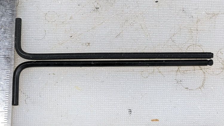
    I came within a heartbeat of cutting the slot parallel to the flat.

    It worked OK while cutting a chunk of stout aluminum tube: so far, so good!

    The impressive chunk of hardware is the OEM blade guide, with the brass tube for coolant flow all over the bearings. It’s mostly intended for use with the diamond blade, so I’ll swap it back in when I finally get around to cutting some slate for base plates.

  • Tour Easy Rear Running Light: First Light!

    Tour Easy Rear Running Light: First Light!

    The rear running light definitely has an industrial look:

    Tour Easy Rear Running Light - installed
    Tour Easy Rear Running Light – installed

    The front of the light has plenty of clearance from the seat mesh:

    Tour Easy Rear Running Light - installed side view
    Tour Easy Rear Running Light – installed side view

    Out on the road, the 1 W LED appears about as bright as automotive running lights:

    Tour Easy Rear Running Light - tunnel
    Tour Easy Rear Running Light – tunnel

    The blink pattern makes it perfectly visible in sunlight, although I’d prefer somewhat larger optics:

    Tour Easy Rear Running Light - sunlight
    Tour Easy Rear Running Light – sunlight

    In shaded conditions, it’s downright conspicuous:

    Tour Easy Rear Running Light - shade
    Tour Easy Rear Running Light – shade

    At any reasonable distance, the 10° beam covers much of the road behind the bike:

    Tour Easy Rear Running Light - distant
    Tour Easy Rear Running Light – distant

    You may not know what the occulting red light represents, but something ahead is worthy of your attention.

    The Arduino source code producing the two dits:

    // Tour Easy Running Light
    // Ed Nisley - KE4ZNU
    // September 2021
    
    #include <morse.h>
    
    #define PIN_OUTPUT  13
    
    // second param: true = active low output
    LEDMorseSender Morser(PIN_OUTPUT,true,(float)10.0);
    
    void setup()
    {
        Morser.setup();
    
        Morser.setMessage(String("qst de ke4znu "));
        Morser.sendBlocking();
    
    //    Morser.setWPM((float)3.0);
        Morser.setSpeed(75);
        Morser.setMessage(String("i   "));
    }
    
    void loop()
    {
        if (!Morser.continueSending())
            Morser.startSending();
    
    }
    

    Looks good to me, anyhow.

  • Tour Easy Rear Running Light: Circuit Support Plate

    Tour Easy Rear Running Light: Circuit Support Plate

    Building the circuit support plate for the amber front running light was entirely too fiddly:

    1 W LED Running Light - baseplate dry assembly
    1 W LED Running Light – baseplate dry assembly

    This was definitely easier:

    Running Light Circuit Plate - solid model
    Running Light Circuit Plate – solid model

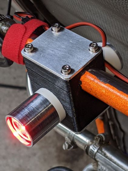
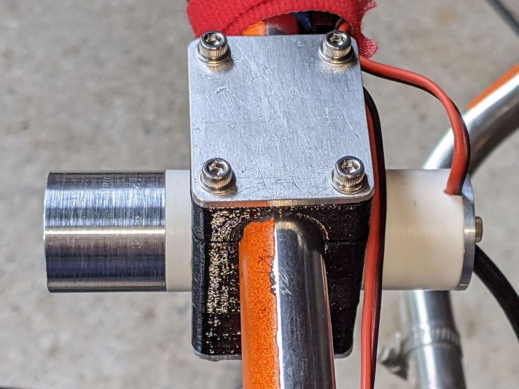
    Two pins fit in the small holes to align it with the LED heatsink, with an M3 stud and brass insert holding it in place:

    Tour Easy Rear Running Light - circuit plate attachment
    Tour Easy Rear Running Light – circuit plate attachment

    The rectangular hole around the insert let me glop urethane adhesive over it to lock it into the plate, with more goop on the screw and pins to unify heatsink and plate.

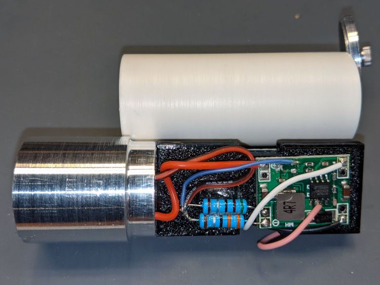
    The LED wires now emerge from the heatsink on the same side of the plate, simplifying the connections to the MP1584 regulator and current-sense resistor:

    Tour Easy Rear Running Light - regulator wiring
    Tour Easy Rear Running Light – regulator wiring

    The paralleled 5.1 Ω and 3.3 Ω resistors form a 2.0 Ω resistor setting the LED current to 400 mA = 1 W at 2.6 V forward drop. They’re 1 W resistors dissipating a total of 320 mW and get barely warm.

    The resistors and wires are stuck in place with clear adhesive, so things shouldn’t rattle around too much.

    The OpenSCAD source code as a GitHub Gist:

    // Circuit plate for Tour Easy running lights
    // Ed Nisley – KE4ZNU – 2021-09
    /* [Hidden] */
    ThreadThick = 0.25;
    ThreadWidth = 0.40;
    HoleWindage = 0.2;
    Protrusion = 0.1; // make holes end cleanly
    function IntegerMultiple(Size,Unit) = Unit * ceil(Size / Unit);
    ID = 0;
    OD = 1;
    LENGTH = 2;
    inch = 25.4;
    //———————-
    // Dimensions
    // Light case along X axis
    LightID = 23.0;
    WallThick = 2.0;
    Screw = [3.0,6.8,4.0]; // M3 OD=washer, length=nut + washers
    Insert = [3.0,4.2,8.0]; // splined brass insert, minus splines
    InsertOffset = 10.0; // insert from heatsink end
    PinOD = 1.6; // alignment pins
    PinOC = 14.0;
    PinDepth = 5.0;
    Plate = [50.0,LightID,Insert[OD] + 4*ThreadThick]; // overall plate size
    WirePort = [10.0,3.0,2*Plate.z];
    NumSides = 2*3*4;
    //———————-
    // Useful routines
    module PolyCyl(Dia,Height,ForceSides=0) { // based on nophead's polyholes
    Sides = (ForceSides != 0) ? ForceSides : (ceil(Dia) + 2);
    FixDia = Dia / cos(180/Sides);
    cylinder(r=(FixDia + HoleWindage)/2,
    h=Height,
    $fn=Sides);
    }
    // Circuit plate
    module Plate() {
    difference() {
    intersection() {
    cube(Plate,center=true);
    rotate([0,90,0])
    cylinder(d=LightID,h=2*Plate.x,$fn=NumSides,center=true);
    }
    rotate([0,90,0]) rotate(180/6)
    translate([0,0,-Plate.x])
    PolyCyl(Screw[ID],2*Plate.x,6);
    rotate([0,90,0]) rotate(180/6)
    translate([0,0,-Plate.x/2 – Protrusion])
    PolyCyl(Insert[OD],Insert[LENGTH] + InsertOffset + Protrusion,6);
    translate([-Plate.x/2 + InsertOffset + Insert[LENGTH]/2,0,Plate.z/2])
    cube([Insert[LENGTH],Insert[OD],Plate.z],center=true);
    for (j=[-1,1])
    translate([-Plate.x/2,j*PinOC/2,0])
    rotate([0,90,0]) rotate(180/6)
    translate([0,0,-PinDepth])
    PolyCyl(PinOD,2*PinDepth,6);
    for (j=[-1,1])
    translate([0,j*(Plate.y/2 – WirePort.y/2),0])
    cube(WirePort,center=true);
    }
    }
    //- Build it
    Plate();