The Smell of Molten Projects in the Morning

Ed Nisley's Blog: Shop notes, electronics, firmware, machinery, 3D printing, laser cuttery, and curiosities. Contents: 100% human thinking, 0% AI slop.

Category: Home Ec

Things around the home & hearth

  • Round Soaker Hose Splint

    Round Soaker Hose Splint

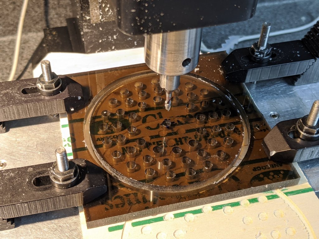
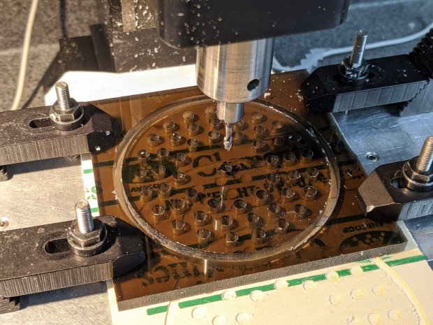
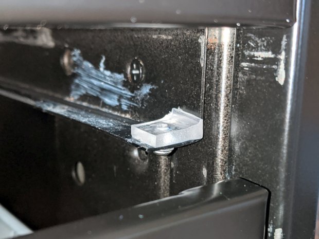
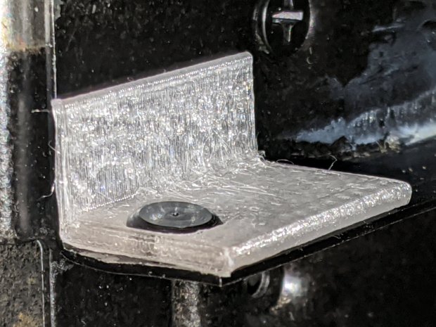
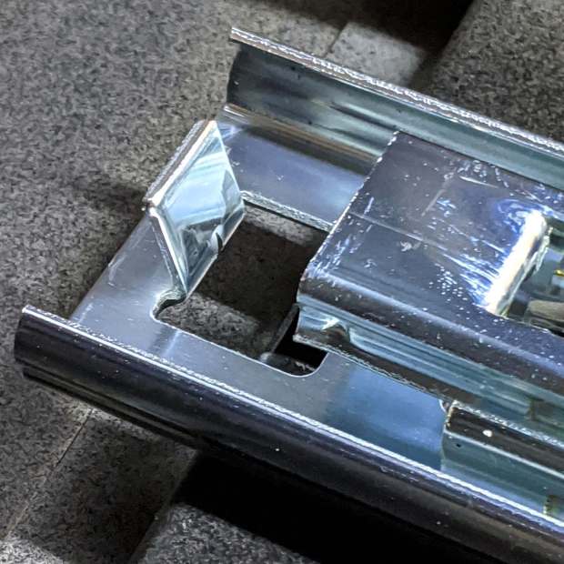
    One of two new round rubber soaker hoses arrived with a slight crimp, enough to suggest it would crumble at an inopportune moment. Rather than return the hose for something that’s not an obvious failure, I clamped the crimp:

    Round Soaker Hose Splice - top
    Round Soaker Hose Splice – top

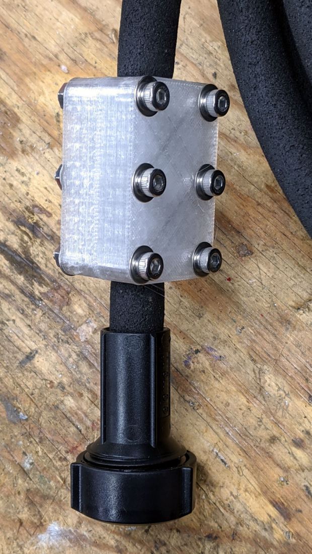
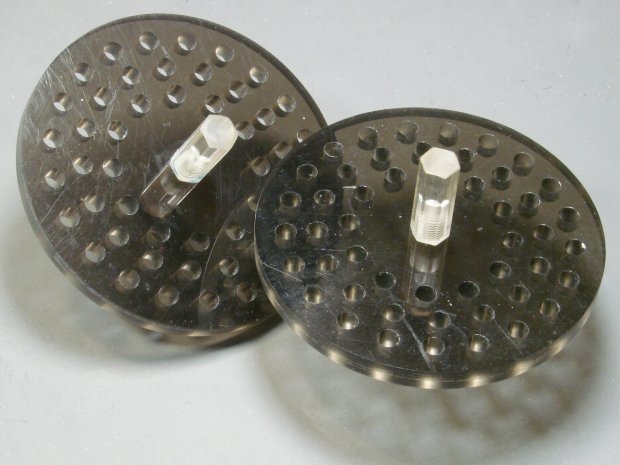
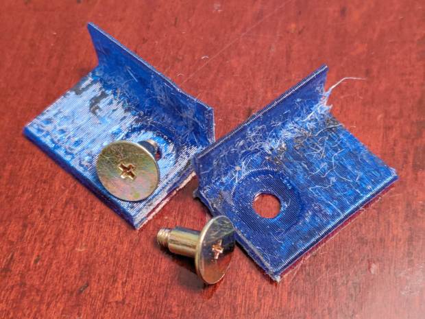
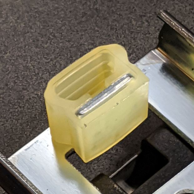
    Unlike the clamps for the punctured flat soaker hoses, this one doesn’t need to withstand much pressure and hold back a major leak, so I made the pieces a bit thicker and dispensed with the aluminum backing plates:

    Round Soaker Hose Splice - bottom
    Round Soaker Hose Splice – bottom

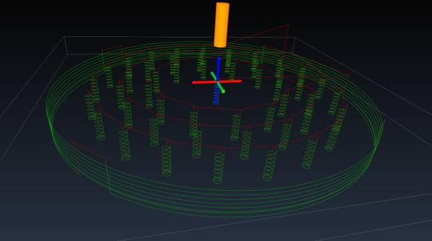
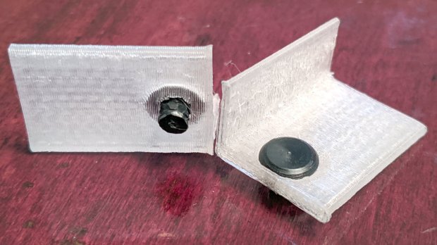
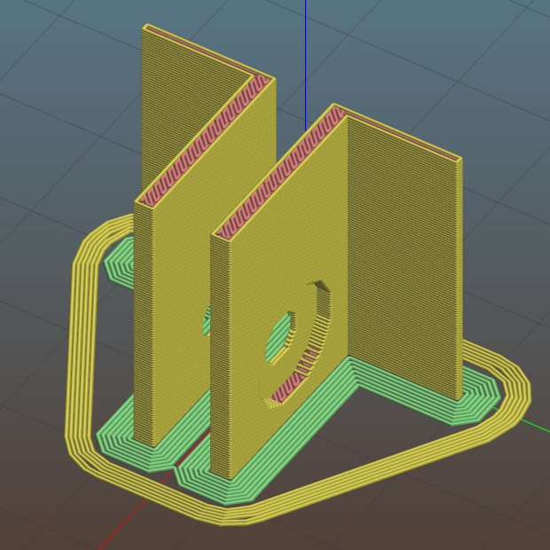
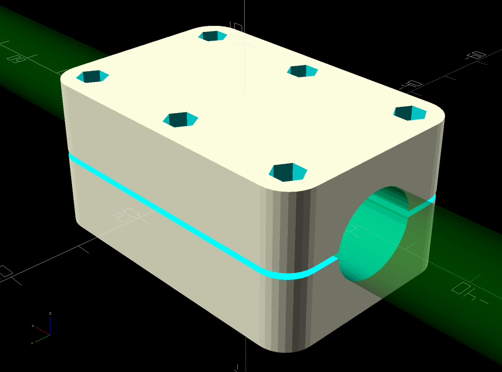
    The solid model is basically the same as for the flat hoses, with a slightly oval cylinder replacing the three channels:

    Round Soaker Hose Splice - OpenSCAD model
    Round Soaker Hose Splice – OpenSCAD model

    The OpenSCAD source code as a GitHub Gist:

    // Rubber Soaker Hose Splice
    // Ed Nisley KE4ZNU 2020-03
    Layout = "Build"; // [Hose,Block,Show,Build]
    TestFit = false; // true to build test fit slice from center
    //- Extrusion parameters must match reality!
    /* [Hidden] */
    ThreadThick = 0.25;
    ThreadWidth = 0.40;
    HoleWindage = 0.2;
    Protrusion = 0.1; // make holes end cleanly
    inch = 25.4;
    function IntegerMultiple(Size,Unit) = Unit * ceil(Size / Unit);
    ID = 0;
    OD = 1;
    LENGTH = 2;
    //———-
    // Dimensions
    // Hose lies along X axis
    Hose = [200,14.5,13.6]; // X = longer than anything else
    // 8-32 stainless screws
    Screw = [4.1,8.0,3.0]; // OD = head LENGTH = head thickness
    Washer = [4.4,9.5,1.0];
    Nut = [4.1,9.7,6.0];
    Block = [50.0,Hose.y + 2*Washer[OD],4.0 + 1.5*Hose.z]; // overall splice block size
    echo(str("Block: ",Block));
    Kerf = 1.0; // cut through middle to apply compression
    CornerRadius = Washer[OD]/2;
    NumScrews = 3; // screws along each side of cable
    ScrewOC = [(Block.x – 2*CornerRadius) / (NumScrews – 1),
    Block.y – 2*CornerRadius,
    2*Block.z // ensure complete holes
    ];
    echo(str("Screw OC: x=",ScrewOC.x," y=",ScrewOC.y));
    //———————-
    // Useful routines
    module PolyCyl(Dia,Height,ForceSides=0) { // based on nophead's polyholes
    Sides = (ForceSides != 0) ? ForceSides : (ceil(Dia) + 2);
    FixDia = Dia / cos(180/Sides);
    cylinder(d=(FixDia + HoleWindage),h=Height,$fn=Sides);
    }
    // Hose shape
    // This includes magic numbers measured from reality
    module HoseProfile() {
    NumSides = 12*4;
    rotate([0,-90,0])
    translate([0,0,-Hose.x/2])
    resize([Hose.z,Hose.y,0])
    cylinder(d=Hose.z,h=Hose.x,$fn=NumSides);
    }
    // Outside shape of splice Block
    // Z centered on hose rim circles, not overall thickness through center ridge
    module SpliceBlock() {
    difference() {
    hull()
    for (i=[-1,1], j=[-1,1]) // rounded block
    translate([i*(Block.x/2 – CornerRadius),j*(Block.y/2 – CornerRadius),-Block.z/2])
    cylinder(r=CornerRadius,h=Block.z,$fn=4*8);
    for (i = [0:NumScrews – 1], j=[-1,1]) // screw holes
    translate([-(Block.x/2 – CornerRadius) + i*ScrewOC.x,
    j*ScrewOC.y/2,
    -(Block.z/2 + Protrusion)])
    PolyCyl(Screw[ID],Block.z + 2*Protrusion,6);
    cube([2*Block.x,2*Block.y,Kerf],center=true); // slice through center
    }
    }
    // Splice block less hose
    module ShapedBlock() {
    difference() {
    SpliceBlock();
    HoseProfile();
    }
    }
    //———-
    // Build them
    if (Layout == "Hose")
    HoseProfile();
    if (Layout == "Block")
    SpliceBlock();
    if (Layout == "Show") {
    difference() {
    SpliceBlock();
    HoseProfile();
    }
    color("Green",0.25)
    HoseProfile();
    }
    if (Layout == "Build") {
    SliceOffset = TestFit && !NumScrews%2 ? ScrewOC.x/2 : 0;
    intersection() {
    translate([SliceOffset,0,Block.z/4])
    if (TestFit)
    cube([ScrewOC.x/2,4*Block.y,Block.z/2],center=true);
    else
    cube([4*Block.x,4*Block.y,Block.z/2],center=true);
    union() {
    translate([0,0.6*Block.y,Block.z/2])
    ShapedBlock();
    translate([0,-0.6*Block.y,Block.z/2])
    rotate([0,180,0])
    ShapedBlock();
    }
    }
    }

  • CNC Kitchen Sink Strainer

    CNC Kitchen Sink Strainer

    Our Young Engineer recently rented a house, now knows why our sinks have CNC-machined strainers, and asked for something better than the disgusting stainless mesh strainer in the kitchen sink.

    Being a doting father, I turned out a pair to get a pretty one:

    CNC Sink Strainer - overview
    CNC Sink Strainer – overview

    They’re made from the same scrap smoked acrylic as the ones in our sinks:

    CNC Sink Strainer
    CNC Sink Strainer

    They’re definitely upscale from the (not watertight!) 3D printed version I built for a Digital Machinist column to explain OpenSCAD modeling:

    Strainer plate fill
    Strainer plate fill

    This time around, though, I rewrote the subtractive design in GCMC, with helical milling for all the holes to eliminate the need to change tools:

    Sink Strainer - tool path simulation - CAMotics
    Sink Strainer – tool path simulation – CAMotics

    They’re done on the Sherline, because it has real clamps:

    CNC Sink Strainer - on Sherline
    CNC Sink Strainer – on Sherline

    Four tabs eliminated the need to reclamp the stock before cutting the perimeter, but I should have ramped, not plunged, through the final cut between the tabs:

    CNC Sink Strainer - tab surface fracture
    CNC Sink Strainer – tab surface fracture

    The handles come from the same chunk of hex acrylic as before, eyeballed to length, tapped 8-32, and secured with acrylic adhesive.

    The GCMC source code as a GitHub Gist:

    // Drill & mill sink drain strainer
    // Ed Nisley KE4ZNU — Digital Machinist 15.2 Spring 2020
    // polycarbonate or acrylic sheet
    // External clamps at corners
    // Origin at center of sheet
    //—–
    // Dimensions
    DiskOD = 80.0mm; // usual kitchen drain = 3-1/4 inch
    DiskRad = DiskOD/2;
    PlateThick = 6.0mm; // stock thickness
    MillOD = 3.170mm; // measured end mill OD
    HoleDia = 4.75mm; // 3/16 inch drain holes
    ScrewOD = 0.18in; // knob screw clearance
    NumRings = 3; // rings of drain holes
    RingSpace = 1.5 * HoleDia; // .. between rings
    MaxZCut = 0.25 * MillOD; // max cut depth
    MillSpeed = 1000mm; // horizontal feedrate
    NumTabs = 4;
    TabTilt = 45deg;
    TabLength = 5.0mm;
    TabThick = 0.5mm;
    SafeZ = 10.0mm; // above all obstructions
    TravelZ = 1.0mm; // within engraving / milling area
    MillZ = -(PlateThick + 0.5mm); // through disk into spoil board
    TwoPi = 2*pi();
    //—–
    // Mill one hole
    function MillHole(ctr,radius,turns) {
    goto([-,-,TravelZ]);
    goto(head(ctr,2) + [radius,-,-]);
    goto([-,-,0]); // kiss surface
    circle_cw(ctr,turns); // helix downward
    circle_cw(head(ctr,2)); // remove last ramp
    goto(ctr); // get elbow room
    goto([-,-,TravelZ]);
    }
    //—–
    // Start cutting!
    goto([-,-,SafeZ]);
    goto([0,0,-]);
    goto([-,-,TravelZ]);
    feedrate(MillSpeed);
    // Mill center screw hole
    comment("– Center hole");
    ctr = [0,0,MillZ];
    MillHole(ctr,(ScrewOD – MillOD) / 2,ceil(abs(ctr.z) / MaxZCut));
    // Mill hole rings
    comment("– Drain hole rings");
    repeat (NumRings; ri) {
    comment("Ring: ",ri);
    rr = DiskRad – ri*RingSpace; // ring radius
    comment(" radius: ",rr);
    nh = to_int(floor(TwoPi*rr / (2*HoleDia))); // number of holes
    comment(" holes: ",nh);
    repeat(nh; h) {
    a = (h – 1) * TwoPi / nh; // angle of hole
    ctr = [rr*cos(a),rr*sin(a),MillZ]; // center point at ending Z
    MillHole(ctr,(HoleDia – MillOD)/2,ceil(abs(ctr.z) / MaxZCut));
    }
    }
    // Mill perimeter
    comment("– Perimeter");
    r = DiskRad + MillOD/2;
    goto([r,0,-]);
    goto([-,-,0]);
    ctr = [0,0,-(PlateThick – TabThick)];
    circle_ccw(ctr,ceil(abs(ctr.z) / MaxZCut)); // ramp downward
    circle_ccw(ctr,1); // remove last ramp
    goto([-,-,TravelZ]);
    comment("– Tabs");
    ta = 360deg / NumTabs; // between tabs
    tsa = to_rad(TwoPi*((TabLength + MillOD) / (TwoPi * r))); // subtended tab angle
    repeat (NumTabs; i) {
    comment(" # ",i);
    a = TabTilt + (i – 1)*ta; // tab center angle
    p0 = [r*cos(a + tsa/2),r*sin(a + tsa/2),MillZ]; // entry on ccw side
    p1 = [r*cos(a + ta – tsa/2),r*sin(a + ta – tsa/2),MillZ]; // exit at next tab
    if (0) {
    comment(" angle: ",a);
    comment(" entry: ",p0);
    comment(" exit: ",p1);
    }
    goto(head(p0,2)); // to entry point
    move(p0); // plunge through
    arc_ccw(p1,r);
    goto([-,-,TravelZ]);
    }
    goto([-,-,SafeZ]);
    goto([0,0,-]);

    All in all, a pleasant diversion from contemporary events …

  • Craftsman Hedge Trimmer: Laying on of Hands Repair

    Craftsman Hedge Trimmer: Laying on of Hands Repair

    It being the season for hacking down decorative grasses, our ancient Craftsman Hedge Trimmer woke up dead, a decade after I fixed its switch and predicted it’d be good for another decade.

    After verifying the failure isn’t in the wall outlet or the extension cord, haul it to the Basement Laboratory Repair Wing, clamp the blade in the bench vise, remove a myriad screws, and pop the top:

    Craftsman Hedge Trimmer - innards exposed
    Craftsman Hedge Trimmer – innards exposed

    I should have removed the screw in the extreme lower right corner and loosened the similar screw at the rear of the bottom plate; they’re two of the three machine screws engaging nuts embedded in the shell. Everything is greasy enough to let the nuts slide right out of the plastic and no harm was done, but that need not be so.

    After poking around a bit and finding nothing obvious, I checked the resistance across the plug: open-circuit with the switch OFF and nearly shorted with the switch ON.

    Huh.

    Put the case back together with just enough screws to prevent heartache & confusion, unclamp the blade, plug into the bench outlet, discover it works fine again, reinstall the rest of the screws, and continue the mission:

    Decorative grass bunches - early spring clearcut
    Decorative grass bunches – early spring clearcut

    We moved the Praying Mantis oothecae to nearby bushes for science!

  • Losing the Battery Bag

    Losing the Battery Bag

    Because the cheap batteries I use in the Sony HDR-AS30V camera provide just slightly less runtime than our longest usual ride after a year of use, I carry a spare battery in a small red felt bag. The bag also holds a USB card reader helping to make the MicroSD card somewhat less lose-able on its trips betwixt bike & desk.

    Here I am, swapping batteries in Adam’s Fairacre parking lot before starting the trip home:

    Losing the Red Bag - setup - 2019-02-25
    Losing the Red Bag – setup – 2019-02-25

    You can see it coming, right?

    Eight minutes later, we’re turning onto the Dutchess County Rail Trail:

    Losing the Battery Bag - flight - 2019-02-25
    Losing the Battery Bag – flight – 2019-02-25

    And then it’s gone:

    Losing the Battery Bag - gone - 2019-02-25
    Losing the Battery Bag – gone – 2019-02-25

    Mary drove past there on her way to a distant meeting, but the little red bag was not to be found anywhere. Maybe it’ll reappear on a fence post or taped to the bulletin board; I’ve tried to return things I’ve found that way.

    I expect somebody got a nice present and, if naught else, it’s good to drop happiness into the world.

    There’s another reader and a quartet of batteries on their way.

  • CVS BP3MV1 Blood Pressure Monitor: Laying on of Hands Fix

    Our CVS blood pressure meter (a relabeled Microlife unit) ran its pump for a few seconds this morning, gave up, and spat out Err 3, which translates into “Inflation of the cuff takes too long”. Not surprising, as the motor wasn’t running.

    The AA alkaline cell quartet has plenty of mojo and no corrosion, but the motor doesn’t even turn over. The display is fine and the pressure release valve clicks, so it’s not completely dead.

    This unit is sufficiently old to have the compelling advantage of transferring data through a USB (mini-B) connection, rather than a Bluetooth link through some sketchy Internet cloudy Android app, so it’s worth at least a look inside. Four screws and some internal snaps along the sides hold the case together; it’s a surprisingly easy teardown.

    The business side of the PCB looks good:

    CVS Blood Pressure Monitor - PCB
    CVS Blood Pressure Monitor – PCB

    The various wires and solder joints for the “high current” parts look OK, although the wires likely don’t go all the way through the PCB:

    CVS Blood Pressure Monitor - PCB detail
    CVS Blood Pressure Monitor – PCB detail

    Q4 and Q5 look like they switch the compressor pump motor and pressure-release valve. D3 and D4 should tamp down the inductive energy, but they look like they’re in series with the outputs. Yes, the Valve wires are both black.

    The motor has a foam vibration isolation wrap, which is a nice touch. Although you can’t see them well, all its wires & solder joints look like they’re in good shape:

    CVS Blood Pressure Monitor - pump
    CVS Blood Pressure Monitor – pump

    The hose sticking out toward you plugs into the black right-angle fitting in the lower right corner of the picture. It’d help to have smaller fingers than mine, but I managed to get the hose off and on the fitting with only minor muttering.

    Seeing nothing obviously wrong, I installed the same batteries, poked the switch to start a measurement, and the motor ran fine. Of course, the measurement failed because the cuff & pressure sensor weren’t connected.

    Connect the hose, plug in the cuff & wrap it around my arm, poke the button, and everything works fine.

    Reassemble everything and it still works fine.

    I still think there’s a bad wire or solder joint in there somewhere, so this delightful “repair” can’t possibly last very long …

  • HON Lateral File Cabinets: Rekeying

    You’d hope the original owner would tape a key inside each file cabinet before donating it to charity; ours arrived unlocked and without keys. Fortunately, eBay sellers have All The Keys and I ordered replacement keys for each cabinet.

    One pair of new keys fit into their lock, but the shoulder didn’t seat properly and the key didn’t turn:

    HON Lateral File - 125E key insertion
    HON Lateral File – 125E key insertion

    Compared with a key for the other cabinet (on the bottom), it seems the tip profile wasn’t quite the same:

    HON Lateral File - 125E key tip
    HON Lateral File – 125E key tip

    Perhaps the underside of the tip hadn’t been cut? Stacking the two keys makes it even more obvious:

    Key 125E tip shaping - vs Key 101E
    Key 125E tip shaping – vs Key 101E

    The eBay seller suggested the lock cores have changed over the years, as other (unaltered) keys fit current cabinet locks. Perhaps HON used fussy high-quality lock cores back in 2004 when they built these cabinets.

    I gingerly filed the 125E key’s tip to match the 101E key and, after several iterations, the shoulder seated firmly in the lock and the core turned smoothly. Flushed with success, I marked the other key of the pair, filed to the mark, and it worked on the first try.

    Mary doesn’t plan to store any secret fabrics in her new cabinets, but now I can declare victory and move on.

  • HON Lateral File: Shelf Rebuild

    HON Lateral File: Shelf Rebuild

    After sliding the HON Lateral File Cabinet shelf into place and installing the bumpers, it seemed rather loose and floppy. Comparing the situation with the other file cabinet showed it had a missing glide button in the rear and two missing slides at the front.

    A replacement button emerged from the end of a Delrin rod:

    HON Lateral File - shelf button - parting off
    HON Lateral File – shelf button – parting off

    The original buttons had an expanding stem, which is easy to do with an injection-molded part. I opted for simple adhesive, with enough of a blob underneath the shelf to (presumably) lock it in place forevermore:

    HON Lateral File - shelf button - installed
    HON Lateral File – shelf button – installed

    The slides required an iterative design technique (pronounced “fumbling around”), because nothing on either side remained square / plumb / true / unbent. I hacked the first version from scrap acrylic, broke off anything that didn’t fit, and got better measurements from what remained:

    HON Lateral File - shelf front guide - size test
    HON Lateral File – shelf front guide – size test

    With those measurements in hand, the second version used a pair of weird flat-head shoulder screws (probably from a hard drive) to anchor 3D printed angle brackets into the frame:

    HON Lateral File - shelf slides - version 2
    HON Lateral File – shelf slides – version 2

    Those worked reasonably well, but PETG doesn’t produce a nice sliding surface, so the final version has flat-head Delrin studs in slightly tweaked brackets:

    HON Lateral File - shelf slides - version 3
    HON Lateral File – shelf slides – version 3

    As with the buttons in the back, the original slides had expanding studs holding them in place, but glue works fine here, too:

    HON Lateral File - shelf slides - version 3 - installed
    HON Lateral File – shelf slides – version 3 – installed

    The button isn’t quite square to the surface and the slide isn’t quite flush with the bent metal in the frame, but it’s Good Enough™ for a shelf that won’t get lots of mileage.

    For reference, the brackets should print vertically to wrap the plastic threads around the upright for better strength:

    HON Lateral File Shelf Slide - Slic3r
    HON Lateral File Shelf Slide – Slic3r

    If you did it the obvious way, the upright side would break right off at the first insult from the hulking shelf, although they’re basically a solid chip of plastic, with a little infill inside the bottom slab.

    While I was at it, I pulled the springs to make them a bit longer, so they touch the back of the frame when the shelf is half an inch behind the front face of the drawers. A firm push and those Delrin contact points let the shelf pop out an inch or so, with plenty of room for fingers underneath the front edge.

    Some drawer slide stops near the back needed attention, too:

    HON Lateral File - slide stop bumper - bent
    HON Lateral File – slide stop bumper – bent

    I cannot imagine how hard somebody slammed the drawers, because bending the stops back to a right angle required a Vise-Grip and some muttering:

    HON Lateral File - slide stop bumper
    HON Lateral File – slide stop bumper

    Oddly, the cushiony hollow side faces away from the drawer, toward the back of the frame, because putting it forward holds the drawer front proud of the front frame face. Maybe HON cost-reduced the steel slides by making them just slightly shorter and using the same bumpers?

    The drawers have begun filling up from boxes scattered around the house:

    HON Lateral File - fabric stash
    HON Lateral File – fabric stash

    That’s the “orange” part of Mary’s collection, now with plenty of room to grow!

    The OpenSCAD source code as a GitHub Gist:

    // HON Lateral File Cabinet
    // Shelf slides
    // Ed Nisley KE4ZNU 2020-02-25
    //- Extrusion parameters must match reality!
    // Print with 3 shells and 3 solid layers
    ThreadThick = 0.25;
    ThreadWidth = 0.40;
    HoleWindage = 0.2;
    function IntegerMultiple(Size,Unit) = Unit * ceil(Size / Unit);
    Protrusion = 0.1; // make holes end cleanly
    inch = 25.4;
    ID = 0;
    OD = 1;
    LENGTH = 2;
    module PolyCyl(Dia,Height,ForceSides=0) { // based on nophead's polyholes
    Sides = (ForceSides != 0) ? ForceSides : (ceil(Dia) + 2);
    FixDia = Dia / cos(180/Sides);
    cylinder(r=(FixDia + HoleWindage)/2,h=Height,$fn=Sides);
    }
    //———————-
    // Dimensions
    SlideBlock = [18.0,25.0,12.0]; // across, along, height of left shelf bracket
    SlideWalls = [1.0,-SlideBlock.y/2,2.0]; // wall thicknesses, dummy Y
    HoleOffset = [8.4,7.0,0]; // hole center from left, front, dummy Z
    HoleOD = 4.0;
    Screw = [4.0,10,0.8]; // weird flat-head shoulder screw
    ScrewRecess = Screw.z + 2*ThreadThick; // depth to keep head below slide surface
    echo(str("Head base: ",SlideWalls.z – ScrewRecess));
    $fn = 12*4;
    //——————-
    // Single slide
    module Slide() {
    difference() {
    cube(SlideBlock,center=false);
    translate(SlideWalls)
    cube(SlideBlock * 2,center=false);
    translate(HoleOffset – [0,0,SlideBlock.z/2])
    rotate(180/8)
    PolyCyl(HoleOD,2*SlideBlock.z,8);
    translate(HoleOffset + [0,0,SlideWalls.z] – [0,0,ScrewRecess])
    rotate(180/12)
    PolyCyl(Screw[OD],3*Screw[LENGTH],12);
    }
    }
    //——————-
    // Build them
    Gap = 5.0/2;
    translate([0,-Gap,0])
    rotate([90,0,0])
    Slide();
    translate([0,Gap,0])
    rotate([-90,0,0])
    mirror([0,1,0])
    Slide();