Ed Nisley's Blog: Shop notes, electronics, firmware, machinery, 3D printing, laser cuttery, and curiosities. Contents: 100% human thinking, 0% AI slop.
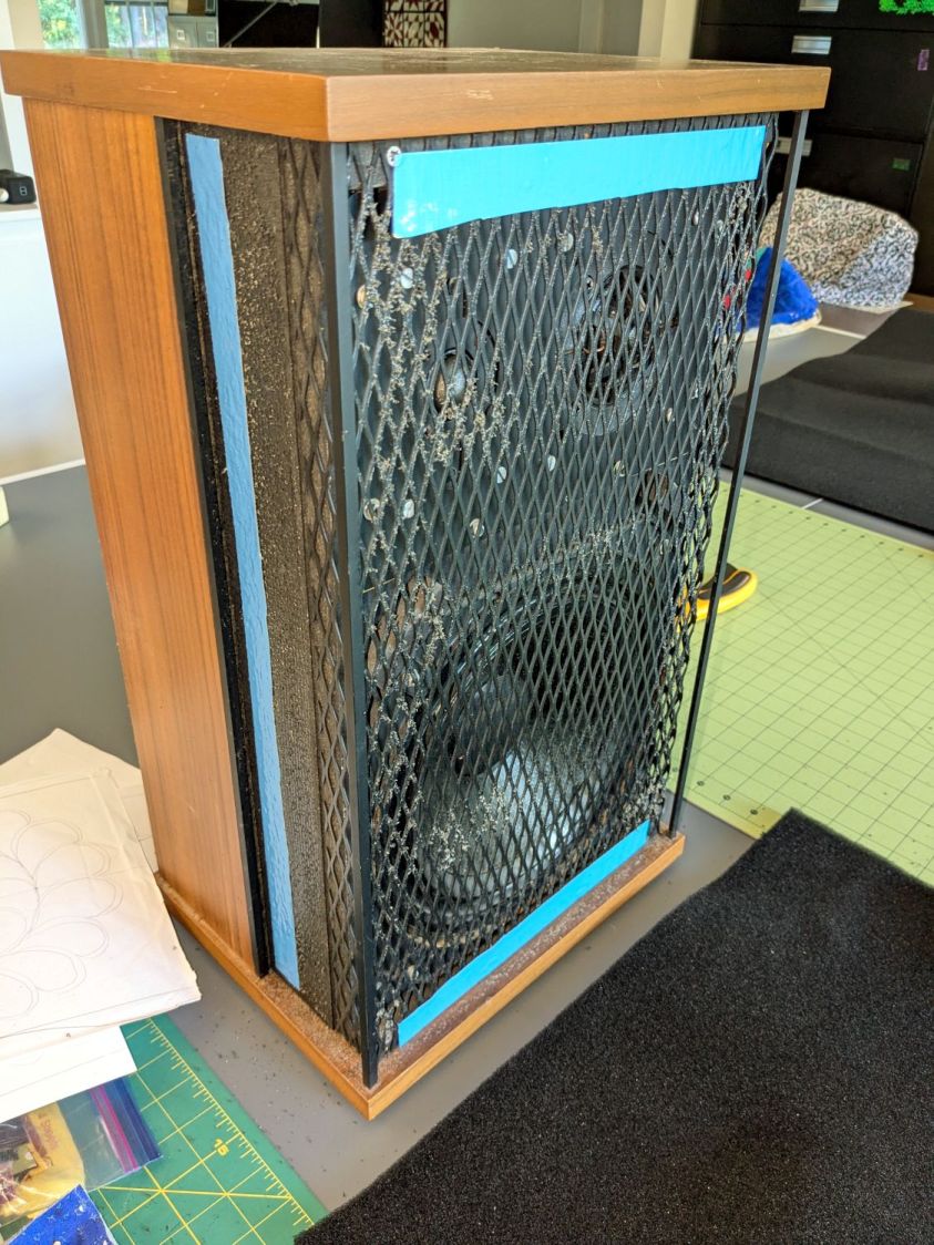
Having recently promoted a pair of Radford Tri-Star 90 speakers to the Sewing Room, it was time to make them presentable:
Radford Tri-Star 90 speakers – taped grill
The original foam grill covering had disintegrated and left fossilized adhesive over the metal gridwork. Being not much for historic accuracy, I used double-sided duct tape (the blue barrier film peels off) and stuck some allegedly acoustic foam in place:
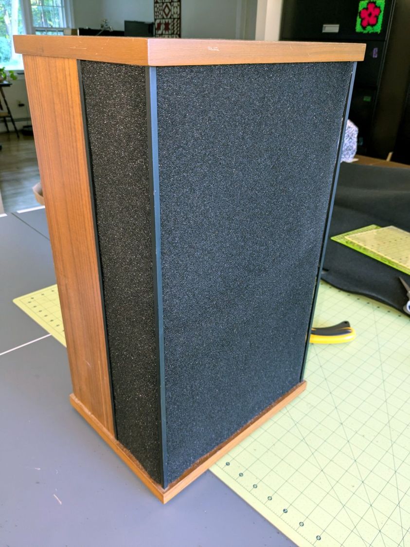
Radford Tri-Star 90 speakers – re-covered
The foam is a single sheet wrapped around three sides and, after some whittling, measured 19.5 inches tall and 19.25 inches wide. The width surely depends on how snugly it’s stretched, so allow a bit more and trim to fit.
Duct tape probably isn’t the right adhesive for the job, but we’ll see how long it lasts. I really did not want to use spray glue and doubted my ability to slobber liquid stickum without oopsing the cones.
The speakers sounded great back in the day and they definitely sound much better than my deflicted ears can hear now. Mary thinks they’re OK and that’s all that matters.
Starting from an SVG file set up for 3 mm material, apply the usual optimizations & tweaks to get a usable LightBurn file, then go nuts:
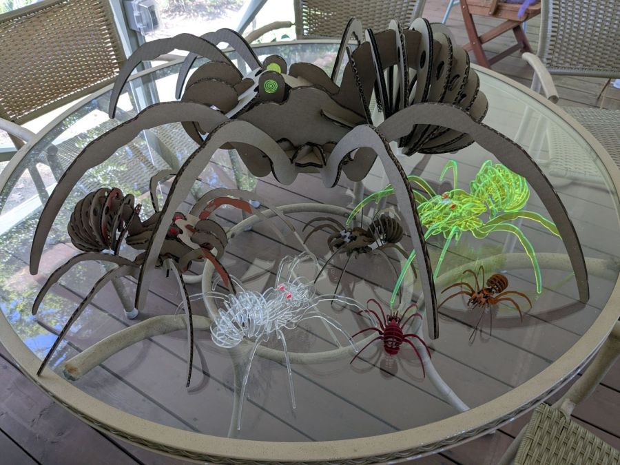
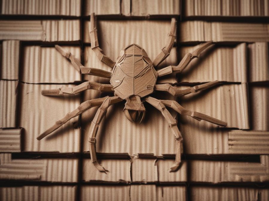
Spider Collection
The big one is two cross-laid layers of corrugated cardboard using up the better part of three Home Depot Large moving boxes:
Spider – LightBurn layout – 2x cardboard
That little bitty grid is the 700×500 mm laser cutter platform, so I just slap a sheet of cardboard in place, update the workspace from the camera, select the next layout, drag it over the cardboard, and Fire The Laser.
The smaller cardboard spider over on the left is built with a single cardboard layer and succumbed to the square-cube law: the legs are entirely too bendy for the weight of the body. Although it’s not obvious from the pictures, both cardboard spiders have a keel plate I added under the body to support most of their weight.
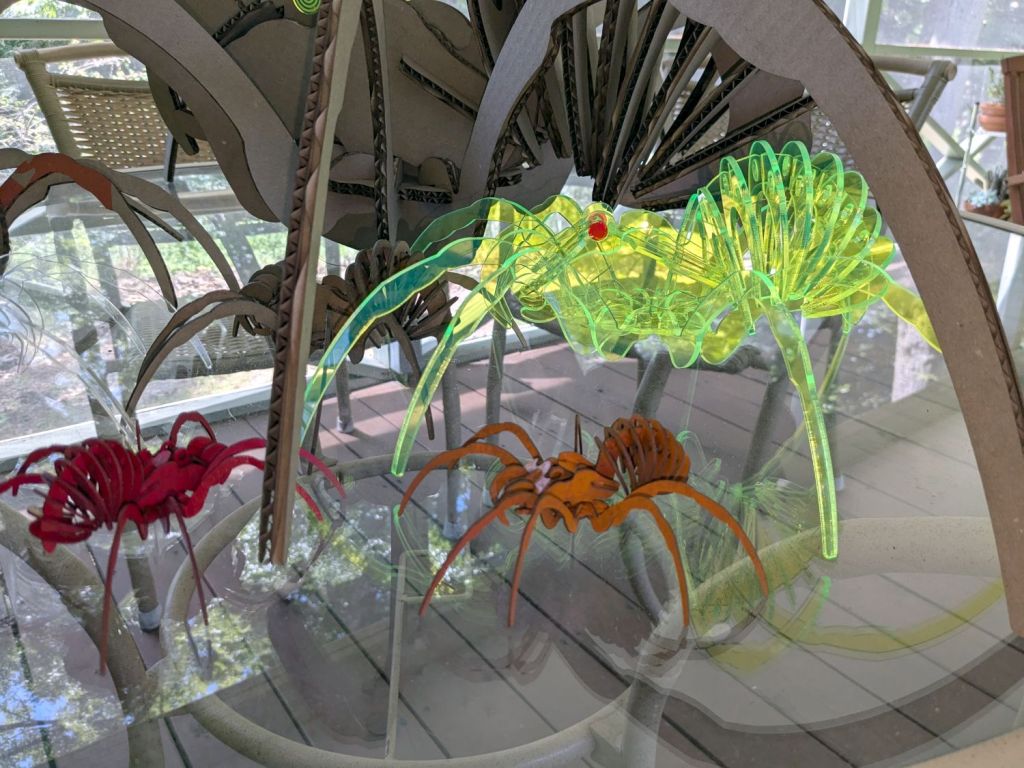
The brightly colored little spiders got a coat of rattlecan paint without any underlying primer and definitely look like that happened:
Spider Collection – detail 2
The edge-lit fluorescent green spider is sized around 2.9 mm material, the clear spider uses 2.3 mm acrylic, and the chipboard one in the background is at 1.8 mm:
Spider Collection – detail 1
The eyes are fluorescent red or green acrylic with concentric circles engraved to catch the light. They’re more effective than I expected, although they won’t look like much after dark.
We now live in a neighborhood with youngsters and Halloween this year will be so much fun …
The WordPress AI image generator caught the general idea of “cardboard spiders”:
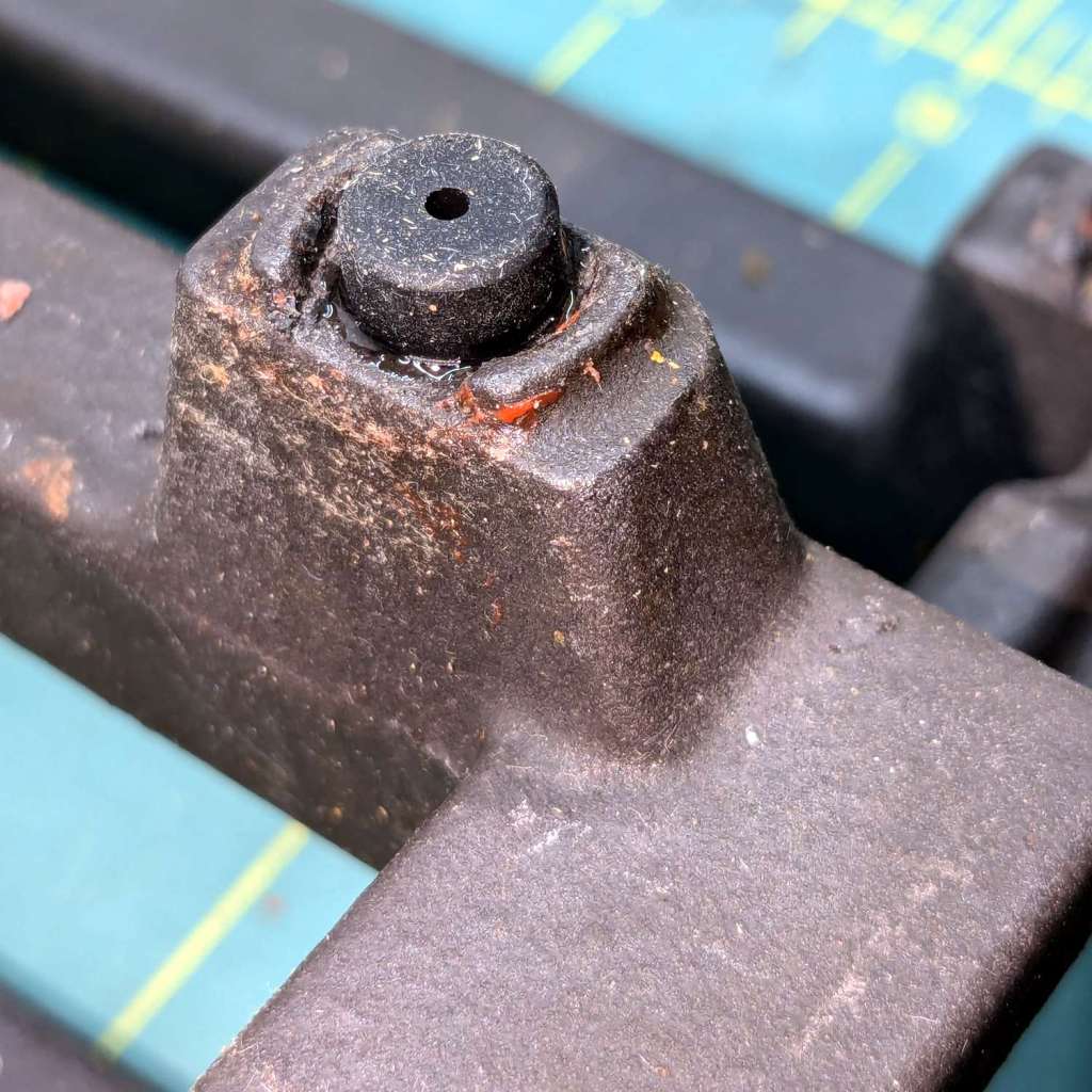
The Samsung range has ungainly cast-iron (or some such) grates that have long since worn out / lost their original Genuine Samsung rubber bumper feet. The grates had glued-on feet that looked very much like they belonged under something else, affixed with mystery adhesive that stuck firmly in some corners and let go in others:
Samsung grate – old foot
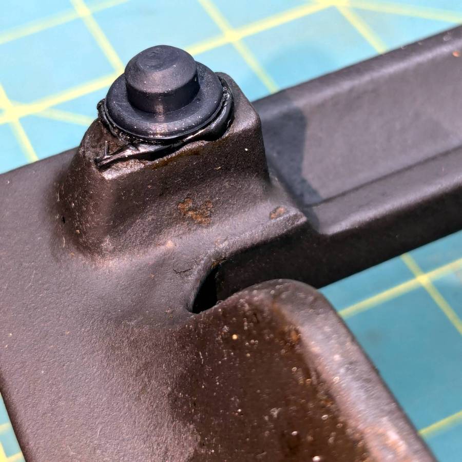
It seems Samsung no longer sells replacement feet, which may be an indication they don’t want customer complaints, so I got a bag of nominally compatible rubber feet from the usual source and broke out the cyanoacrylate glue:
Samsung grate – new foot
The red flecks are traces of a previous generation of adhesive, with the new cyanoacrylate peeking out around the base of the new foot.
The grates have holes for the stems of the feet, so in principle they have plenty of resistance to being shoved around. In practice, tipping the grates up to clean underneath them dislodged the feet with depressing regularity. The grates are too heavy and too awkward to remove and plunk somewhere else, which suggests this sort of range is better suited to a kitchen that’s never used or, perhaps, comes equipped with a support staff.
You’re supposed to use high-temperature adhesive and, in fact, the red flecks look remarkably like high-temp silicone gasket compound, but all the missing feet were along the back of the grates where the small & simmer burners live, so I figured cyanoacrylate was certainly worth a try.
When & if they fall out, I’ll know when they went in.
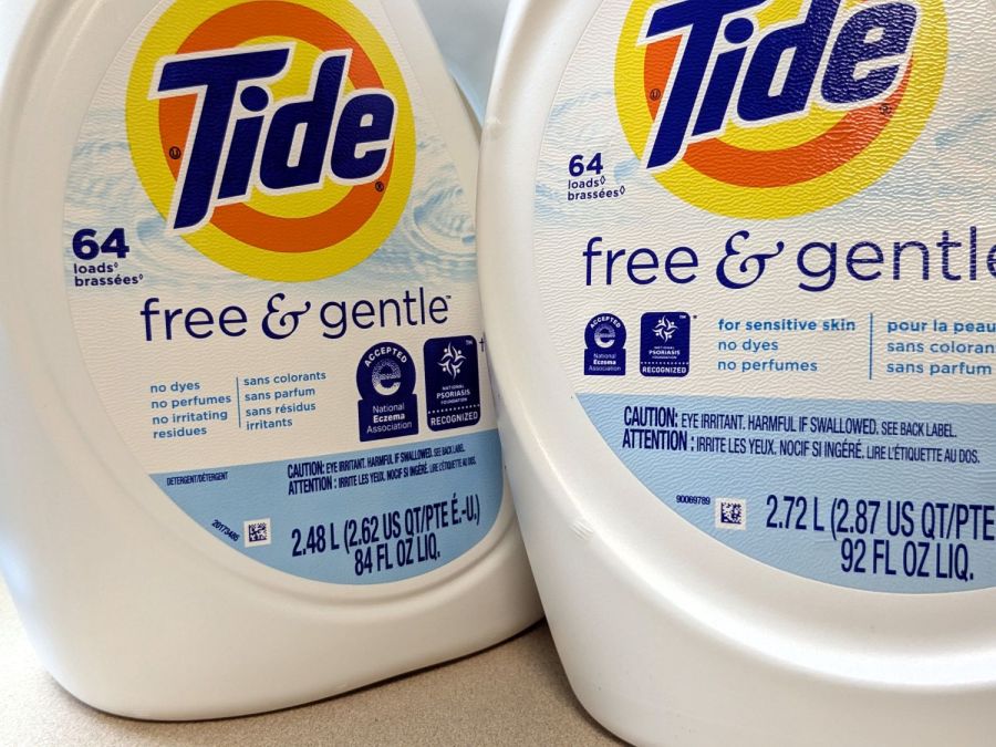
The most recent Tide HE Laundry Detergent bottles seemed smaller than the one we were about to empty and, indeed, they were:
Tide HE shrinkflation – bottle labels
Call it 9% smaller, based on the volume in liters. I suspect the price was also 9% higher, but that would require more digging in the file cabinet than seems justified.
Note that both bottles claim “64 loads”, each with an asterisk (well, a lozenge ◊ symbol) explained on the label:
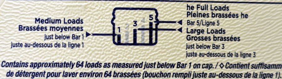
Tide HE shrinkflation – new load bars
That’s the new chart. The old chart was more explanatory:
Tide HE shrinkflation – old load bars
Note the “just below Bar 1 on cap” weasel wording. The term “meniscus” enters the chat, although laundry detergent doesn’t have much in the way of surface tension.
One might reasonably assume the bars on the new cap have gotten shorter, so that the volume of detergent used for each load would be smaller.
One would be wrong:
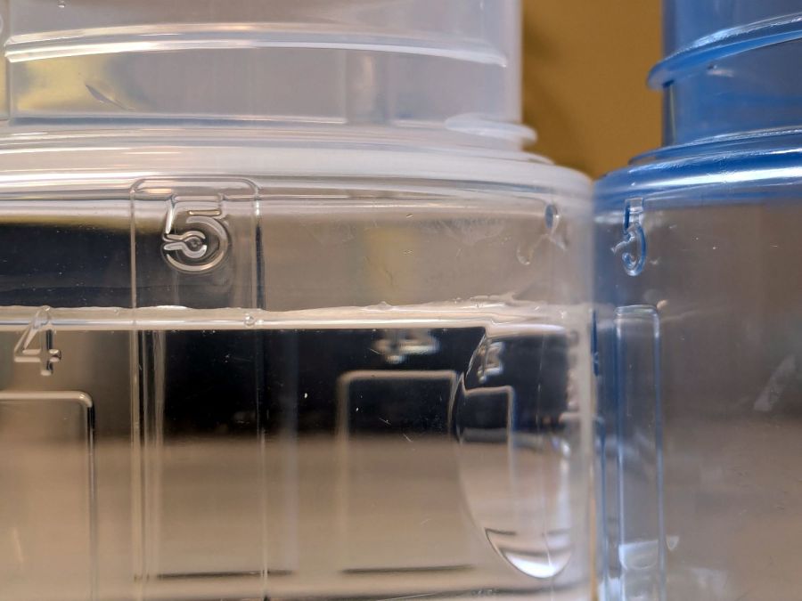
Tide HE shrinkflation – cap capacity marks
The blue cap on the right is one we’ve been using for the last few years, because I put black tape at the level of the first bar to match our “Medium” loads. I cannot imagine how much dirt would require filling the cap to Bar 5.
The clear cap on the left is the new cap. I filled the blue tap to the top of Bar 5 with water and poured it into the clear cap, where it comes about 3/4 of the way to the top of the new Bar 5. Evidently, the amount of detergent required to get grubby clothes clean has increased by 33%.
The old cap holds just shy of 4 fluid ounces to the top of Bar 5:
Tide HE shrinkflation – old cap bar 5 capacity
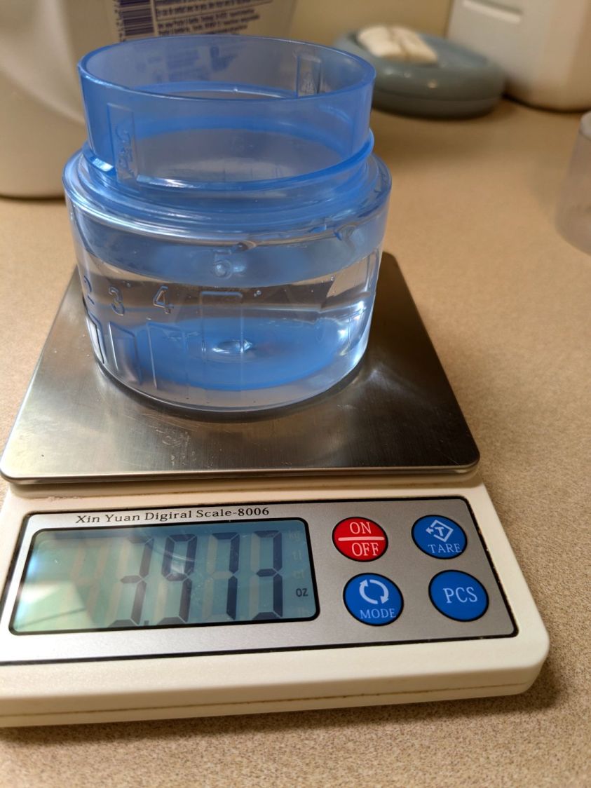
The new cap holds 5.5 fluid ounces to the top of its Bar 5:
Tide HE shrinkflation – new cap bar 5 capacity
If you have really crusty clothing, you’re now using 36% more detergent per load.
The obvious arithmetic shows the old bottle holds 23 “Bar 5” loads and the new bottle holds 15.
To the limit of my measuring ability, both caps hold 1.3 fluid ounces to the top their respective Bar 1 levels. I cannot vouch for the “just below” level, but I suspect more accurate measurements would show the new caps have slightly lower volume at that level, juuust enough to make the “64 loads” weasel wording come out right.
Earlier this year, a pair of House Finches chose the a pine cone wreath hanging outside our front door for their nest.
One day a Starling attacked:
Starling Attack – IM_00052
Starling Attack – IM_00053
Starling Attack – IM_00054
There’s a Youtube video of the action following those pictures:
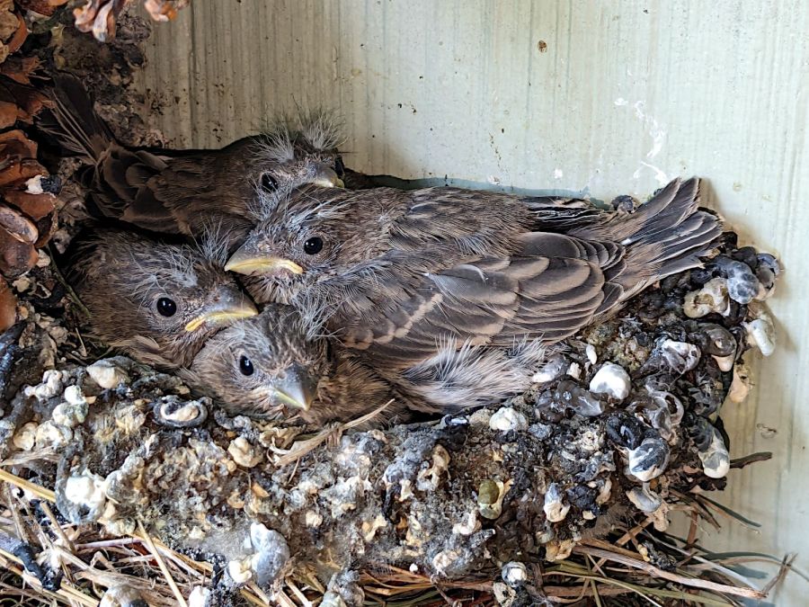
Ms. Finch suffered a peck to the head raising a few feathers into a small topknot, but seemed otherwise undamaged. The eggs survived unscathed and a month later they fledged a quartet of new finches:
House Finch chicks – pre-fledging – 2024-05-18
Yes, they’re surrounded by a ring of bird crap: finch chicks can aim and fire overboard, but they don’t have much range.
The same finch pair abandoned their second nest after a Brown-headed Cowbird added an egg and punctured both Finch eggs:
House Finch nest – Cowbird egg vs punctures
Their third attempt failed after four eggs when a Cowbird added a fifth:
House Finch nest – Cowbird egg with 4 finch eggs
A few days after that picture, something tore that nest apart and destroyed all the eggs:
House Finch nest – destruction with feathers
The scattered feathers suggest a major battle with severe injuries.
Three nesting attempts produced only four fledglings: a bad year for those two finches.
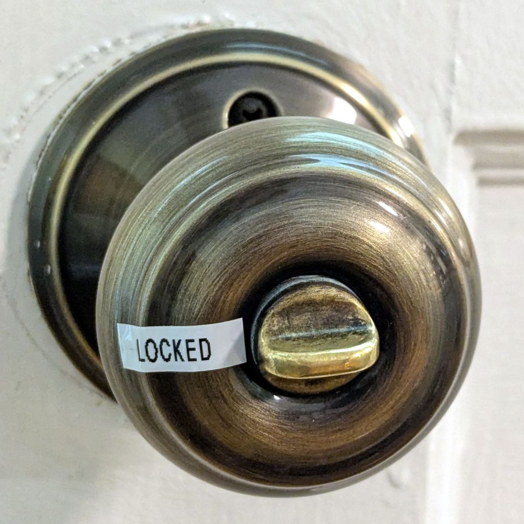
For the usual historic reasons, the exterior doors on our house all have different knobs with different lock orientations (and keys), so it’s difficult (for me, anyway) to verify they’re locked with just a glance. The correct solution of replacing all the knobs seems like a great deal of effort & expense for very little benefit.
This is easier, albeit considerably less stylish:
Doorknob 1
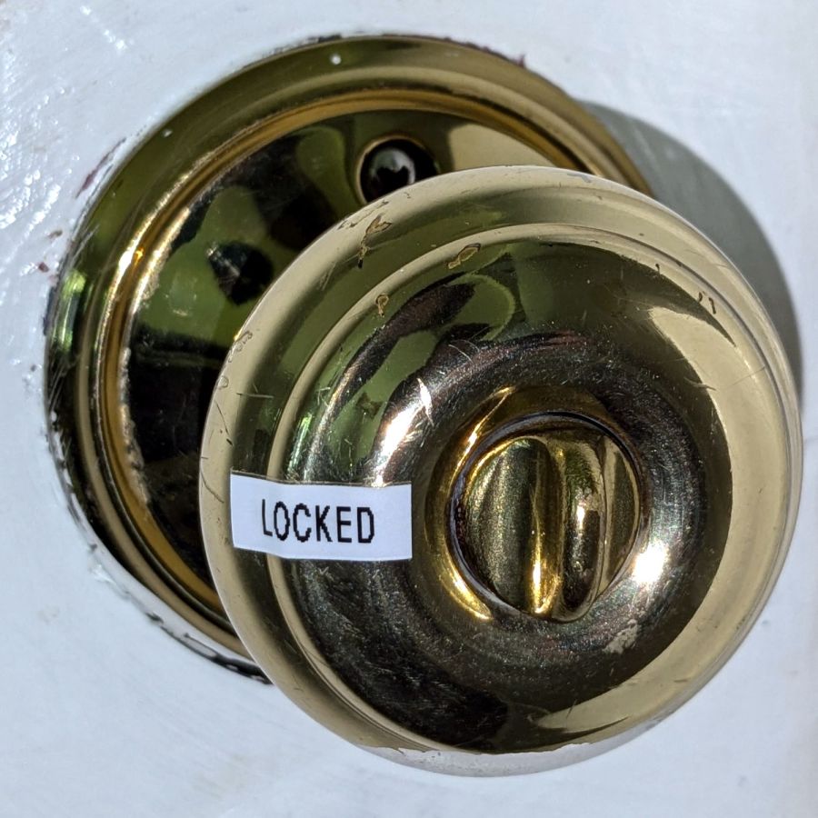
When the twisty thing aligns with the label, it’s locked:
Doorknob 3
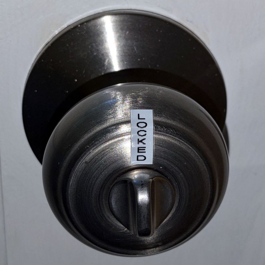
No matter what orientation it has:
Doorknob 2
The scars in the paint show some of those doors have sported many knobs over the last half century or so.
You’d think such a thing could be standardized, but nope.
If we lived in a fancier house, I probably couldn’t get away with it.
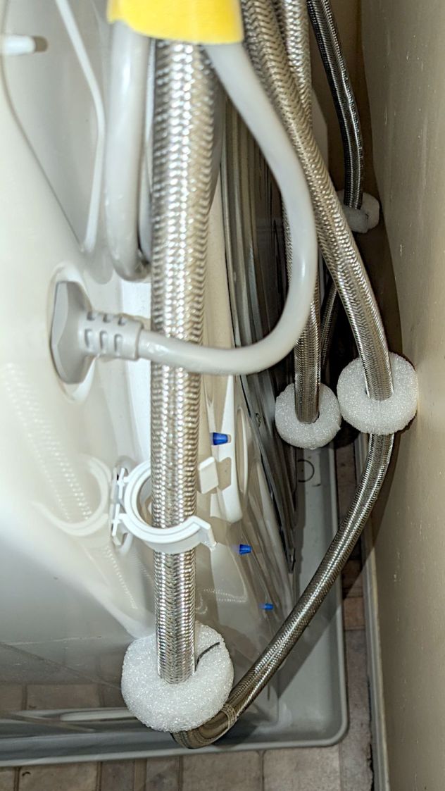
For obvious reasons, the water hoses tend to thump against the wall and the sheet-metal back of the clothes washer, so I added foam disks to mute the noise:
Clothes washer hose bumpers
They’re closed-cell polyethylene foam, laser-cut from a sheet about 15 mm thick. The cut is a yawning 2 mm wide near the top, but it pretty much doesn’t matter in this application.
The black line in the split is a snippet of the usual outdoor-rated foam tape, which probably won’t stick well to PE foam. If these fall apart, a cable tie around their waist should suffice.
The nice clip in the foreground is one of two intended to corral the drain hose. It’d be nice if LG included a few clips for the water hoses, but no matter where they were, the hoses would want to go elsewhere.