The Smell of Molten Projects in the Morning

Ed Nisley's Blog: Shop notes, electronics, firmware, machinery, 3D printing, laser cuttery, and curiosities. Contents: 100% human thinking, 0% AI slop.

Category: Home Ec

Things around the home & hearth

  • HQ Sixteen: Thread Spool Adapter

    HQ Sixteen: Thread Spool Adapter

    The HQ Sixteen consumes thread at a prodigious rate, so it’s set up for large thread cones. Mary sometimes uses ordinary thread spools (leftovers from sewing projects) for short practice sessions and wanted an adapter to hold the little things in place:

    Thread spool adapter - installed
    Thread spool adapter – installed

    Those of long memory should recall previous adapters for both sizes and their notes about how thread should peel off spools & cones. I considered an adapter with a horizontal spool axis, but contemporary machines apparently don’t bother with such niceties. We may need a right-angle adapter to let the thread pull off from the side, but we’ll start simple and fix it if needs be.

    Update: It needed fixing.

    The solid model looks about like you’d expect:

    HQ Sixteen - thread spool adapter - solid model
    HQ Sixteen – thread spool adapter – solid model

    The small crosswise hole in the hub gets an M3 setscrew pushing a rubber pellet slightly into the central bore for a friction fit. The OpenSCAD code can distribute any number of such holes, but one seemed entirely adequate.

    The code shrinkwraps a hull() around two cylinders to create the tapered sides, thus giving the thread less surface to drag across. I have PrusaSlicer set to produce scarf joints around the perimeter and the edges came out surprisingly smooth, with only one rough spot requiring deft Xacto knife work. It’s made from white PETG for a smoother finish than PETG-CF.

    The OpenSCAD code consists mostly of constants defining the various physical measurements and a few lines assembling the model:

    // HQ Sixteen - thread spool adapter
    // Ed Nisley - KE4ZNU
    // 2025-01-21
    
    include <BOSL2/std.scad>
    
    /* [Hidden] */
    
    PinOD = 0.25*INCH;
    
    RingOD = 50.0;      // outer perimeter of thread ring
    RingEdge = 3.0;     // height of ring edge & tapers
    RingAngle = 45;     // upper & lower tapers wrt vertical
    
    RingOAH = 3*RingEdge;
    
    ScrewOD = 2.5;      // tap for setscrew compressing rubberdraulic piston
    NumScrews = 1;
    
    HubOD = 25.0;
    HubThick = 2*ScrewOD;
    HubSides = 12;
    
    ScrewCL = RingOAH + HubThick/2;
    
    AdapterOAH = HubThick + RingOAH;
    
    Protrusion = 0.1;
    
    NumSides = 12*3*4;   // smooth outer perimeter
    
    //----------
    // Build it
    
    
    difference() {
        union() {
    
            hull() {
                linear_extrude(RingOAH)
                    circle(r=RingOD/2 - RingEdge*tan(RingAngle),$fn=NumSides);
    
                up(RingEdge)
                    linear_extrude(RingEdge)
                        circle(d=RingOD,$fn=NumSides);
            }
    
            linear_extrude(HubThick + RingOAH)
                rotate(180/HubSides)
                    circle(d=HubOD,$fn=HubSides);
    
        }
    
        down(Protrusion)
            rotate(180/HubSides)
                cylinder(d=PinOD,h=2*AdapterOAH,$fn=HubSides);
    
       for (i=[0:NumScrews-1]) {
            a = i*360/NumScrews;
            zrot(a)
                up(ScrewCL)
                    yrot(90)
                        zrot(180/6)
                            cylinder(d=ScrewOD,h=HubOD,$fn=6);
        }
    
    }
    

    Putting the adapter in the light box revealed the same problem as photographing white dogs in snowstorms:

    Thread spool adapter - white on white
    Thread spool adapter – white on white

    There was no contrast to be enhanced anywhere, although the rubber pellet definitely stands out.

  • Hotel California: Vole Edition

    Hotel California: Vole Edition

    Although we had considerable success trapping voles during the last half of the 2024 gardening season, Mary found a description of what might be a better technique: a box with small entrance holes taking advantage of rodent thigmotaxis: their tendency to follow walls. The writeup shows nicely made wood boxes, but I no longer have machinery capable of cutting arbitrarily large wood slabs into pieces.

    I do, however, have a vast pile of cardboard boxes:

    Vole Box - large
    Vole Box – large

    That’s a rat-size trap.

    A smaller box has room for two mouse-size traps (one hidden on the left):

    Vole Box - small
    Vole Box – small

    The general idea: plunk the box in a garden plot, arm the trap(s), close the lid, and eventually a vole will venture inside, whereupon wall-following leads to disaster. Apparently bait is optional, as wall-following inevitably takes them over the trap pedal. I won’t begrudge them a walnut or two, should bait become necessary.

    Cardboard is obviously the wrong material for a box in an outdoor garden, but I figure they’ll survive long enough to show feasibility and I can deploy a lot of small boxes before having to conjure something more durable.

    Yes, those are laser-cut rounded-rectangle holes: 30 mm and 40 mm, assuming voles care about such things.

    Edit: More on voles.

  • Clothes Dryer Inlet Filter Holder

    Clothes Dryer Inlet Filter Holder

    It has always seemed like a Bad Idea™ to run indoor air through the clothes dryer and dump it overboard, particularly during days when the indoor air has been painstakingly (perhaps expensively) heated or cooled. The dryer now lives in a separate room with two doors, so we can close it off from the rest of the house and let it inhale outdoor air through the screen on the storm door.

    Except in winter, when a glass pane covers the screen. Propping the door open just a bit is unattractive, because an open door seems like an invitation to any field mouse looking to upgrade its domicile.

    Given that the dryer exhausts through a length of 4 inch flexible duct, I figured a similar vent, facing inward, mounted on the storm door would admit enough air to keep it happy. Keeping insects and adroit mice out requires a screen:

    Dryer Inlet Vent - filter retainer
    Dryer Inlet Vent – filter retainer

    After taking that picture, I rammed four threaded brass inserts into the holes, thereby eliminating the need for a handful of washers and nuts, some of which were absolutely certain to disappear through gaps in the deck.

    The two blue-gray rings are PETG-CF:

    Dryer Inlet Vent Filter Retainer - solid model
    Dryer Inlet Vent Filter Retainer – solid model

    The small split makes the inner retainer just springy enough to fit over the two small tabs normally locking a dryer hose in place.

    The OpenSCAD code gloms a few shapes together:

    include <BOSL2/std.scad>
    
    /* [Hidden] */
    
    VentID = 102.0;     // diameter at base of vent opening
    VentOD = 107.5;
    
    OpenAngle = 3;
    
    LipWidth = 3.0;         // lip around vent opening
    LipThick = 7.5;
    
    StrutWidth = 2.5;       // wide enough to hold filter
    StrutThick = 3.0;       // tall enough to be rigid
    NumStruts = 3;
    
    Protrusion = 0.1;
    
    NumSides = 360/6;
    
    $fn=NumSides;
    
    //----------
    // Build it
    
    union() {
    
        linear_extrude(LipThick)
            ring(NumSides,d1=VentID - 2*LipWidth,d2=VentID,angle=[OpenAngle/2,360-OpenAngle/2],spin=270);
    
        linear_extrude(StrutThick) {
            circle(r=StrutWidth);
    
            for (i=[0:(NumStruts-1)]) {
                a = 90 + i*360/NumStruts;
                zrot(a)
                    right(VentID/4)
                        square([VentID/2 - LipWidth/2,StrutWidth],center=true);
            }
        }
    
        linear_extrude(LipThick)                // outside trim ring
            ring(NumSides,d1=VentOD,d2=VentOD+2*LipWidth);
    }
    

    The overall union() keeps PrusaSlicer from identifying the thing as a multi-material model. Apparently, it still looks enough like a logo to qualify for special treatment, but I fought it to a standstill.

    Installation awaits an above-freezing day …

  • CD/DVD Data Destruction: Engraving

    CD/DVD Data Destruction: Engraving

    A LightBurn video suggested large scan line intervals for decorative effects, so I adapted the SCP warning labels to fit 4 inch CD/DVD discs, set up the fixture, and Fired The Laser:

    CD Engraving - fixture
    CD Engraving – fixture

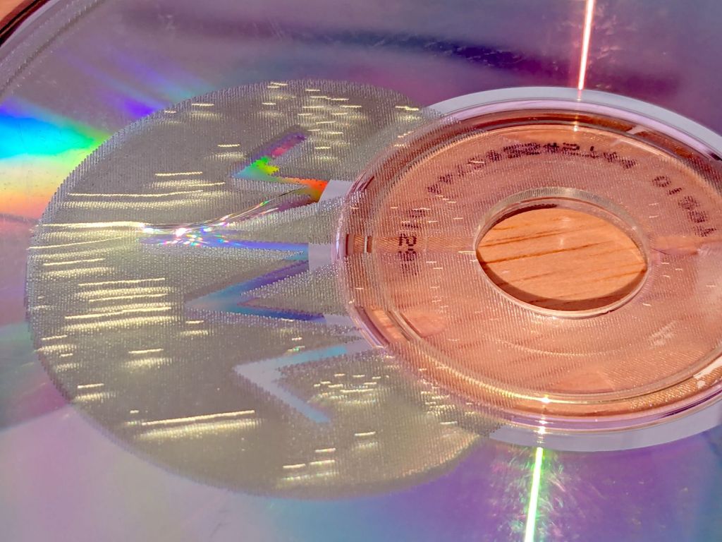
    The overall effect is, in most lighting, subtle:

    CD Engraving - samples 2
    CD Engraving – samples 2

    The pair on the right with inverted engraving areas are bolder:

    CD Engraving - samples 1
    CD Engraving – samples 1

    From a distance these two look similar, but a line interval of 0.50 mm (on the left) produces a distinct lined effect compared to the overall frosty look for 0.25 mm (open in a new tab & zoom in):

    CD Engraving - vary interval
    CD Engraving – vary interval

    The left and right edges of the disc warp upward as the surface melts and cools, pulling the disc into a potato chip shape. Doing large areas with 0.5 mm spacing produces less warp than 0.25 mm.

    The laser barely fires at 10% power (on the right) and produces a line with a distinct granular look compared the smoother result at 20% (on the left), both at 0.50 mm interval to show the lines:

    CD Engraving - vary power
    CD Engraving – vary power

    A 2 mm border at 0.25 mm interval (on the right, with a DVD) appears lighter than the central area at 0.50 mm (the CD on the left does not have the border):

    CD Engraving - interval passes
    CD Engraving – interval passes

    A closer look at the border:

    CD Engraving - low power irregularity
    CD Engraving – low power irregularity

    The reason behind the granular effect at 10% power is more obvious with higher magnification:

    CD Engraving - interval passes - detail
    CD Engraving – interval passes – detail

    The spots off to the right are surface imperfections and dirt, not random laser tube firing.

    The border and the central area happen on two different passes, so it’s comforting to see how closely the scan lines match.

    I glued pairs of discs together with E6000 adhesive to discover whether it’s less awful than cutting and aligning adhesive sheets. Yup, much better, but white adhesive requires better path control to keep it out of the transparent ring around the hub and better quantity control to prevent blobs from squooshing out around the perimeter. Using clear adhesive would help, as would a fresh tube without a plug of cured gunk blocking the nozzle.

    Once again, I have Too Many Coasters.

  • HQ Sixteen: Heisenbug vs. Schematic

    HQ Sixteen: Heisenbug vs. Schematic

    After running reliably for a few weeks, the HQ Sixteen Heisenbug returned, displaying a Motor Stall error on the first attempt to run the motor. This gave me the opportunity to extract the PCB, compare it with the first rough schematic, then correct a few resistor values and connections.

    Redrewing (most of) it in somewhat canonical form:

    HQ Sixteen - Power PCB - schematic 2025-01-14
    HQ Sixteen – Power PCB – schematic 2025-01-14

    As before:

    • Do not assume any connections or components are correct or correctly drawn.
    • !!CAUTION!! The motor supply is direct-from-the-AC-line non-isolated +160 VDC.
    • !!CAUTION!! The GND traces are not isolated from the AC line and are not at the normal “0 V” AC neutral potential.

    When the machine operates normally, the relay pulls in with a distinct click slightly after the power switch closed. With the Heisenbug in full effect, the relay does not click, suggesting a fault in its driver circuitry.

    With the motor pod resting on a box beside the machine, I gingerly measured the voltage at various points on the top of the PCB. As far as I could tell, the entire +15 VDC power supply was dead: no voltage at either the input or output terminal of the LM7815 regulator!

    NOTE: The obvious screws along the top edge of the PCB are not connected to the power PCB circuit GND. Instead, they’re part of the controller’s power circuitry from the isolated power supply produced by rectifier bridge B3 and passed through J1 in the upper left corner of the PCB. Instead, the left lead on R1 (the 5W sandbox resistor) is a convenient GND terminal.

    So I hauled the little DSO150 battery-powered oscilloscope and a handful of clip leads up from the Basement Laboratory, got everything arranged, turned on the power, and the machine worked perfectly again.

    That’s why it’s called a Heisenbug: look at it and it vanishes.

    Given a faint indication of power supply problems, I verified all four diodes in Bridge Rectifier B21 are OK and the Skynet transformer windings were solid. I resoldered all the PCB connections from the transformer to U2, the LM7815 regulator, plus the green jumper wires.

    The machine is now back together, it continues to work, and all my test equipment is back in the basement.

    If it happens again, I’ll mount a cheerful LED on the pod to show the supply is working.

  • Whole House Filter Disassembly

    Whole House Filter Disassembly

    The sediment and carbon filter cartridges in our house call for annual replacement and I wondered what was inside the big cartridge.

    Much to my surprise, the white plastic cap unscrews easily after grabbing the filter in the bench vise and applying a strap wrench:

    Whole house carbon filter - endcap
    Whole house carbon filter – endcap

    Water enters around the perimeter of the cap, flows through the media in the cylindrical cartridge, and emerges near the center at the other end. The filter is upside-down in the vise: the cap is on the bottom of the cartridge when it’s installed in the filter housing.

    The brown stuff looks a lot like sand, but is probably KDF-85 media acting as a prefilter for the carbon:

    Whole house carbon filter - prefilter
    Whole house carbon filter – prefilter

    The white fiber pad separates the KDF-85 from the carbon granules filling the rest of the filter:

    Whole house carbon filter - carbon
    Whole house carbon filter – carbon

    Atypically, I couldn’t think of anything to do with the empty cartridge, so I screwed the lid back on and lowered the whole mess into the trash can.

    Now I know what’s inside!

  • Samsung Refrigerator Condenser Coil Cleaning

    Samsung Refrigerator Condenser Coil Cleaning

    The kitchen came with matched Samsung appliances dating back to 2018 and, on a frigid winter day, we piled the contents of the freezer on the porch and gave it a deep cleaning. While the empty freezer was cooling down from its adventure, I wondered:

    • Where were the condenser coils were located?
    • Did they need cleaning?
    • How does one do that?

    The manual is strangely silent about even the existence of the coils, so evidently cleaning them wasn’t of any importance to Samsung.

    Rolling the refrigerator away from the wall just enough to get the phone camera down there suggests they exist and are in need of some attention:

    Samsung refrigerator coils - first sight
    Samsung refrigerator coils – first sight

    Rolling the refrigerator out until the door handles met the countertop across the way let me climb over the counter and worm myself into the refrigerator-sized hole behind it, bringing along a screwdriver, the vacuum cleaner snout, and a few brushes.

    Removing five screws released the back cover:

    Samsung refrigerator coils - cover off
    Samsung refrigerator coils – cover off

    Looking into the intake end of those coils (on the right):

    Samsung refrigerator coils - first intake view
    Samsung refrigerator coils – first intake view

    So, yeah, I’m about to give them their first cleaning ever.

    Five minutes of brushing fuzz, mostly into the vacuum, cleared a good bit of the exterior, but the interior needs more attention:

    Samsung refrigerator coils - partial clean
    Samsung refrigerator coils – partial clean

    Ten minutes later:

    Samsung refrigerator coils - victory
    Samsung refrigerator coils – victory

    Another five minutes:

    Samsung refrigerator coils - intake cleaned
    Samsung refrigerator coils – intake cleaned

    Making the coils cleanable and putting them where they could be cleaned were obviously not bullet-item goals for Samsung’s designers.

    Although the coils are not perfectly clean, I don’t know how to get them any cleaner, despite knowing even a thin layer of fuzz kills the refrigerator’s much-touted energy efficiency. Perhaps blowing them off with compressed air, then cleaning a thin layer of dust off the entire kitchen, would help.

    I think the refrigerator will be happier, at least for a while.