The Smell of Molten Projects in the Morning

Ed Nisley's Blog: Shop notes, electronics, firmware, machinery, 3D printing, laser cuttery, and curiosities. Contents: 100% human thinking, 0% AI slop.

Category: Home Ec

Things around the home & hearth

  • Garden Hose Fitting Grip: MVP

    Garden Hose Fitting Grip: MVP

    The garden hose leading from the standpipe / hose bibs outside Mary’s garden to her drip irrigation plumbing has an octagonal fitting requiring more torque than her hand can easily produce. I offered to make a larger grip for the fitting, which amounts to a disk with a grippy rim sized to her hand and an interior opening suitable for gluing to the fitting.

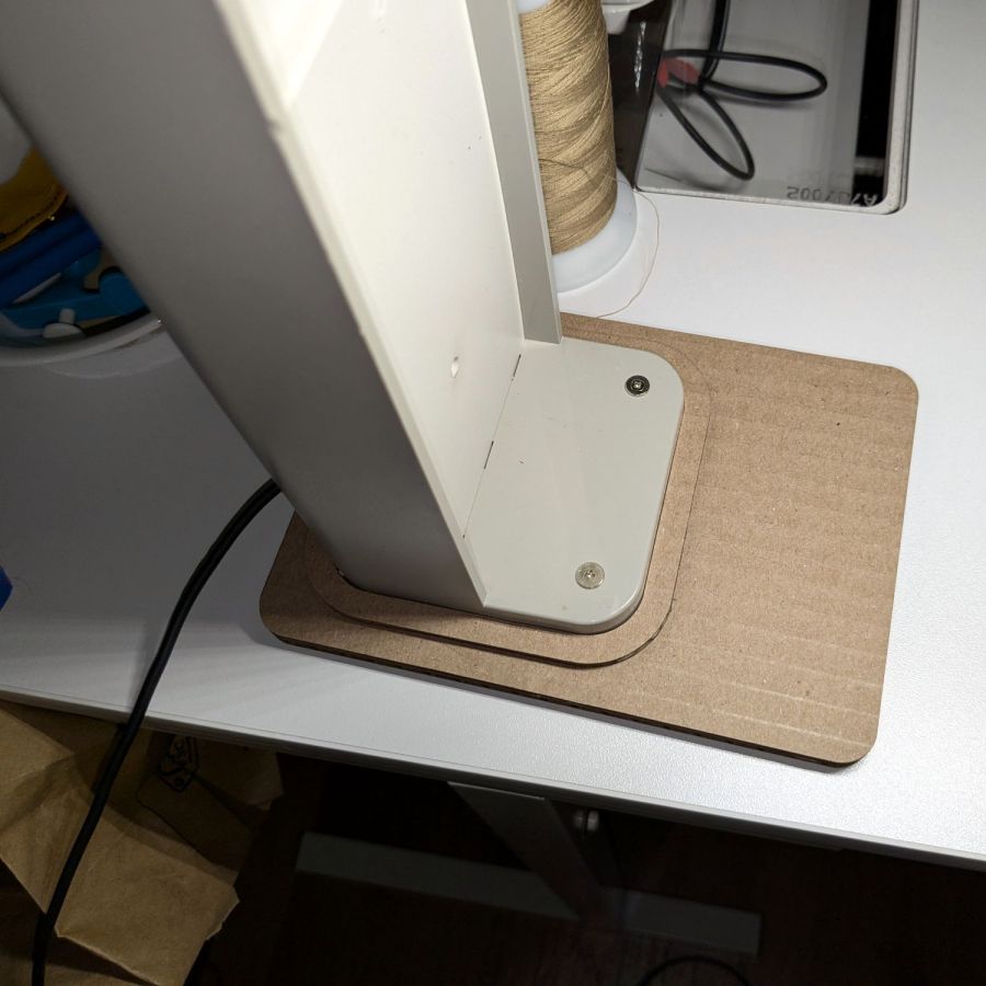
    A couple of laser-cut MDF sizing prototypes accompanied me to the garden:

    Hose Fitting Grip - MDF prototype
    Hose Fitting Grip – MDF prototype

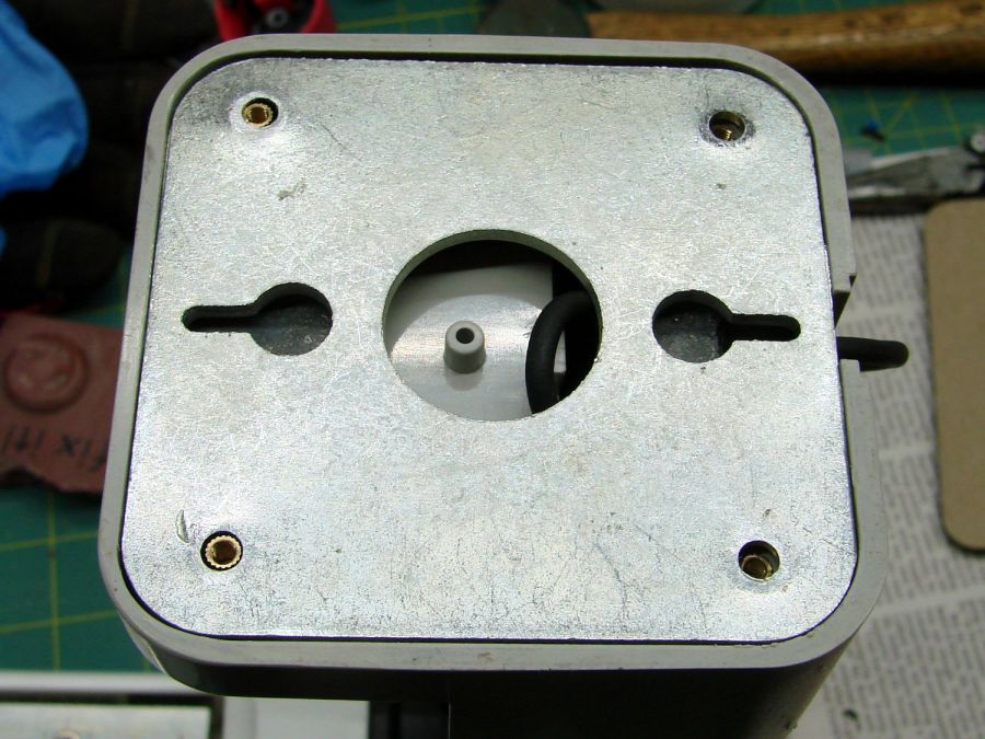
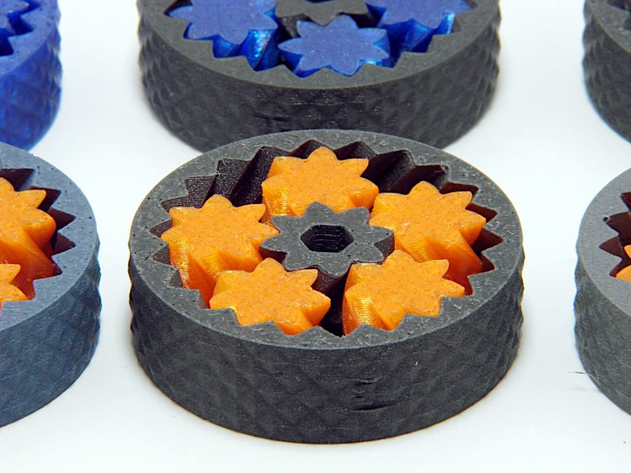
    The springy fingers around the fitting soak up the inevitable distortions found in a battered hose and will eventually be filled with adhesive to lock the grip in place.

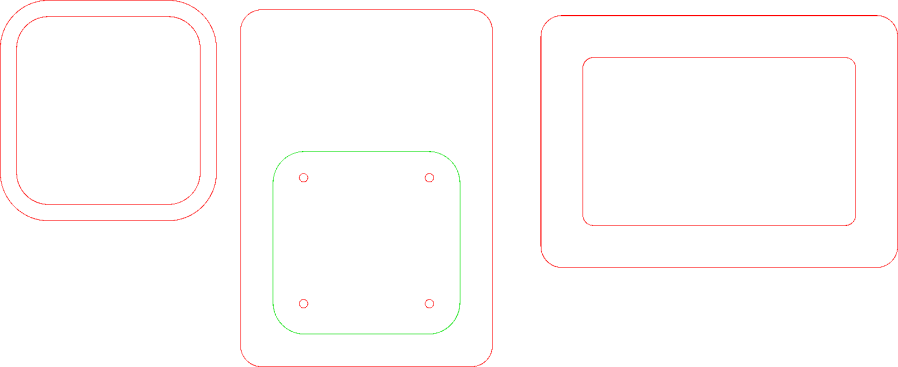
    MDF being obviously the wrong material for a permanent installation, the final grip will be 3D printed, with the LightBurn layout modified to produce the internal structure:
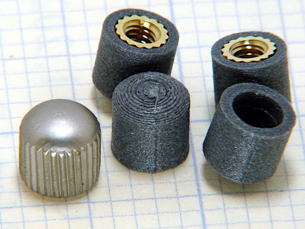
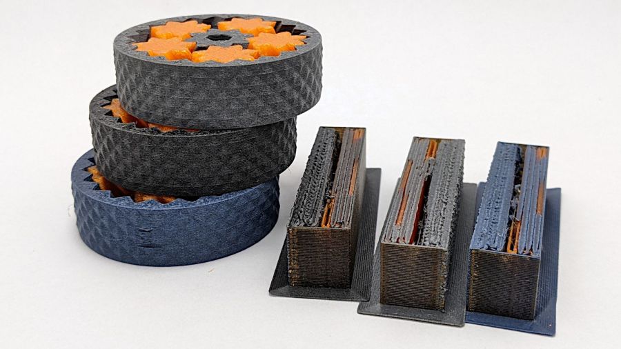
    Hose Fitting Grip - LightBurn layers
    Hose Fitting Grip – LightBurn layers

    From left to right:

    • The stacked pieces in order of printing
    • Main grip with springy fingers
    • Spacer keeping the fingers away from the narrower opening
    • Support layer
    • Narrow opening to align the grip with the end of the fitting

    Exporting the SVG images and making a bank shot off Inkscape to create layer names:

    Hose Fitting Grip - Inkscape layers
    Hose Fitting Grip – Inkscape layers

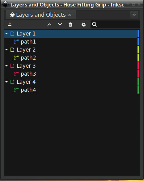
    The ascending layer name + numbers allow a simple OpenSCAD program to extract the SVG shapes by name, extrude them to the proper thickness, put them at the proper height, then combine the result:

    Recenter = [-140,-108,0];
    
    Thick = [0,8.0,1.0,0.2,1.0];
    Level = [0,
             Thick[1],
             Thick[1]+Thick[2],
             Thick[1]+Thick[2]+Thick[3],
             Thick[1]+Thick[2]+Thick[3]+Thick[4]];
    Colors = ["Black","Red","Gray","Yellow","Green"];
    
    union()
        for (i = [1:len(Thick)-1]) {
            color(Colors[i])
                translate(Recenter + [0,0,Level[i-1]])
                    linear_extrude(height=Thick[i],convexity=10)
                        import("/mnt/bulkdata/Project Files/Laser Cutter/Gardening/Hose Fitting Grip/Hose Fitting Grip - Inkscape layout.svg",
                               layer=str("Layer ",i));
        }
    

    The hideous mess generating the Level vector happens because OpenSCAD does not have mutable variables and I hate retyping numbers. One can use a recursive function to add the values, but copypasta makes more sense in this case.

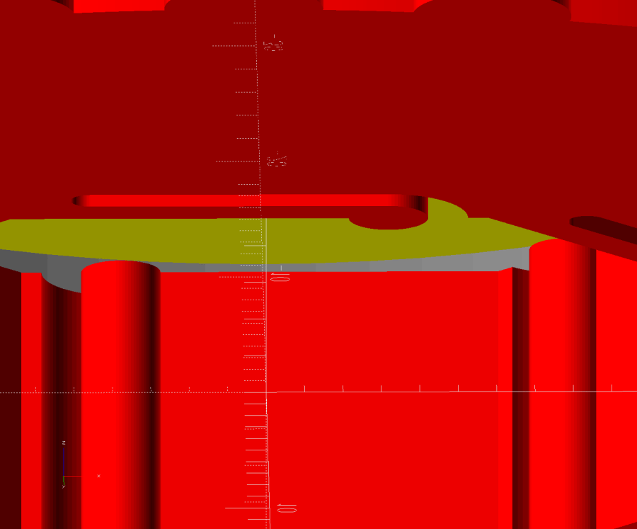
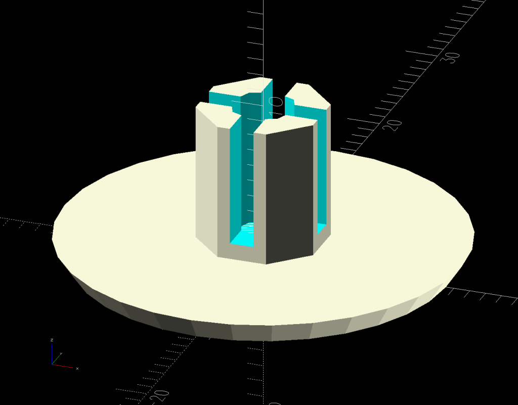
    Which produces this solid model, with garish colors for pedagogic purposes:

    Hose Fitting Grip - top - solid model
    Hose Fitting Grip – top – solid model

    The thin yellow band will be one thread thick to provide support for the green layer with a smaller ID than the springs below it. The gray layer below the yellow is the air gap above the springs.

    Peering inside the bottom shows the (gray) layer providing clearance between the springs and the (yellow) support layer:

    Hose Fitting Grip - bottom interior - solid model
    Hose Fitting Grip – bottom interior – solid model

    Exporting the model as a 3mf file, importing it into PrusaSlicer, and slicing it with suitable parameters (Extrusion Multipler = 0.8) does what you’d expect. This top view shows the internal structure just below the support bridge across the middle:

    Hose Fitting Grip - spring detail - PrusaSlicer
    Hose Fitting Grip – spring detail – PrusaSlicer

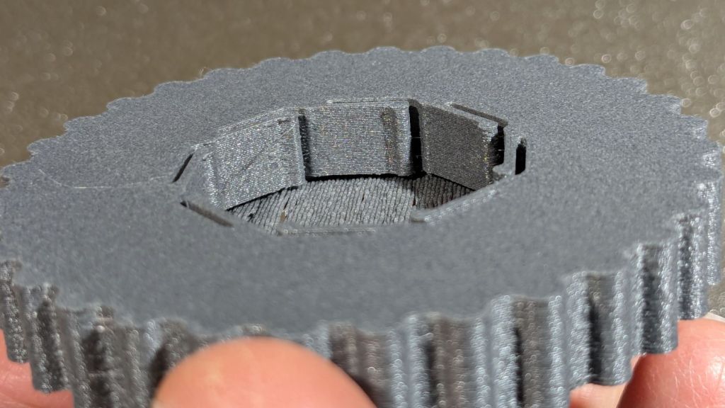
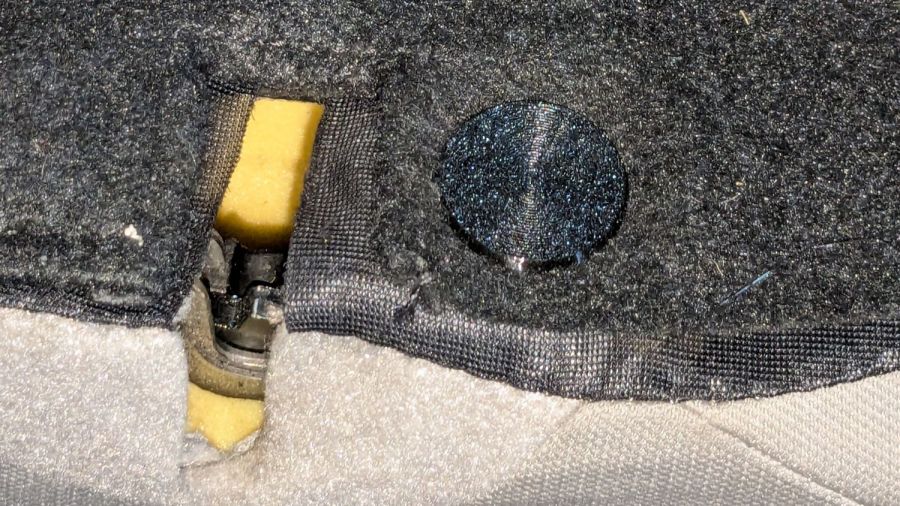
    Printing it in gray PETG-CF was uneventful, with the bridging layer coming out surprisingly well:

    Hose Fitting Grip - as printed
    Hose Fitting Grip – as printed

    The springs definitely have an air gap in there:

    Hose Fitting Grip - printed interior
    Hose Fitting Grip – printed interior

    And the support layer cuts out neatly with an Xacto knife:

    Hose Fitting Grip - support removed
    Hose Fitting Grip – support removed

    We’ve had enough rain over the last few days (something to do with a continental-scale storm) to keep me and my adhesives out of the garden, but it hasn’t needed any watering, either.

  • Bathtub Soap Tray V2

    Bathtub Soap Tray V2

    As expected, the adhesive foam strips I used on the bathtub soap tray didn’t survive continued exposure to hot soapy water, so Version 2 includes hooks securing it to the ceramic soap tray and a few other tweaks:

    Bathtub Soap Tray - V2 - LightBurn layout
    Bathtub Soap Tray – V2 – LightBurn layout

    The view from the top:

    Soap Tray V2 - top
    Soap Tray V2 – top

    The hooks are more visible from the bottom, as is the 10 AWG copper wire preventing the whole affair from rotating around the ceramic handle from the weight of the soap bar:

    Soap Tray V2 - bottom
    Soap Tray V2 – bottom

    Ignore the usual crud you’ll find on your ceramic soap tray, too.

    This time I glued things together with Weld-On IPS #3 acrylic solvent.

    The LightBurn layout as a GitHub Gist:

    Loading
    Sorry, something went wrong. Reload?
    Sorry, we cannot display this file.
    Sorry, this file is invalid so it cannot be displayed.
  • Converted OttLite Rebasing

    Converted OttLite Rebasing

    The OttLite I converted into a NisLite fell over again and, now having a way to make the long-promised base, this happened:

    Converted Ottlite - cardboard base
    Converted Ottlite – cardboard base

    It’s not particularly elegant, what with being cardboard, but it’s a proof of concept that will determine the final size.

    The top layer is a ring around the lamp pedestal for a bit of stabilization protecting the four M3 screws holding the base to the lamp. Those screws sit on a 60 mm square, offset 1 mm to the front of the lamp:

    NisLite Baseplate - LightBurn layout
    NisLite Baseplate – LightBurn layout

    Which explains why I typically make the first few versions of anything out of cardboard.

    For the record, those inserts look like this:

    Converted Ottlite - brass inserts
    Converted Ottlite – brass inserts

    A pair of very flat-head M3 screws hold the front inserts in place through holes match-drilled in the remains of the bosses I’d long ago epoxied in place. I pressed the rear inserts in place by misusing the drill press, as the lamp is much too tall for the heat setter.

    Then comes the iron base weight:

    Converted Ottlite - iron weight
    Converted Ottlite – iron weight

    And then the steel outer plate:

    Converted Ottlite - steel cover plate
    Converted Ottlite – steel cover plate

    The new base plate gets a ring around its perimeter for clearance under the four pan head M3 screws into the inserts.

    If the cardboard base is stable enough, we’ll do an acrylic version in cheerful primary colors.

    The LightBurn layout in SVG format as a GitHub Gist:

    Loading
    Sorry, something went wrong. Reload?
    Sorry, we cannot display this file.
    Sorry, this file is invalid so it cannot be displayed.
  • Ceiling Lamp Nuts

    Ceiling Lamp Nuts

    While cleaning dead bugs out of the ceiling lamps, we discovered the kitchen light was missing one of the three nuts holding its cover in place. While spare nuts might be available, this seemed like a quicker & easier solution:

    Ceiling Lamp Nut - bottom view - solid model
    Ceiling Lamp Nut – bottom view – solid model

    The stepped interior fits a brass insert with 8-32 threads (not metric, to my utter astonishment) rammed in place with a heat-set tool:

    Ceiling Lamp Nut - insert staking
    Ceiling Lamp Nut – insert staking

    Using the nominal diameters seems to work fine, although I’m sure some finesse will be needed with smaller inserts.

    Printed four just to be sure, rammed three inserts, and they’re ready:

    Ceiling Lamp Nuts - as-built
    Ceiling Lamp Nuts – as-built

    The curved cap matches the original nut through the use of the Chord Equation to get the cap radius as a function of its height (sagitta) & base diameter. Admittedly, it looks kinda grotty with only a dozen layers, but it’s the thought that counts.

    The original nuts are heavy knurled steel and the new ones are cheap plastic, but nobody will ever know:

    Ceiling Lamp Nut - installed
    Ceiling Lamp Nut – installed

    Bonus: now I have two spare steel nuts for the next time …

    The OpenSCAD source code:

    // Nuts for LED ceiling light fixture
    // Ed Nisley KE4ZNU
    // 2024-09-27
    
    KnurlLength = 7.4;
    KnurlOD = 9.0;
    
    CapOD = 9.0;
    CapHeight = 2.0;
    CapRadius = (pow(CapHeight,2) + pow(CapOD,2)/4)/(2*CapHeight);
    echo(CapRadius=CapRadius);
    
    NumSides = 1*(2*3*4);
    $fn = NumSides;
    
    Protrusion = 0.1;
    
    difference() {
        union() {
            intersection() {
                translate([0,0,KnurlLength + CapHeight - CapRadius])
                    sphere(r=CapRadius);
                translate([0,0,KnurlLength])
                    cylinder(d=2*KnurlOD,h=KnurlLength);
            }
    
            cylinder(d=KnurlOD,h=KnurlLength);
    
        }
    
    // Ad-hoc 8-32 brass insert sizes
    
        cylinder(d=5.5,h=8.0);
        cylinder(d=5.9,h=5.7);
        cylinder(d=6.2,h=2.2);
        translate([0,0,-Protrusion])
            cylinder(d=6.2,h=2.2);
    
    }
    
  • Subaru Upholstery Peg

    Subaru Upholstery Peg

    One of the flat-topped pegs anchoring the fuzzy black upholstery / carpet to the back of the rear seats went walkabout a while ago, but the situation only became critical after I vacuumed the crud out of the car.

    Living in the future simplifies things:

    Upholstery Peg - solid model
    Upholstery Peg – solid model

    Rather than getting all fancy with barbed ends and suchlike, I just slathered the stem with hot-melt glue, jammed it in place, and waited a few breaths:

    Upholstery peg - installed
    Upholstery peg – installed

    The vivid yellow stuff is seat cushion foam.

    3D printing is wonderful for simple parts like that.

    The OpenSCAD source code is simple enough:

    // Upholstery pin for Subaru back seat
    // Ed Nisley KE4ZNU
    // 2024-09-13
    
    HeadThick = 1.5;
    HeadOD = 25.0;
    
    PegLength = 10.0;
    PegOD = 8.0;
    SlotWidth = 1.5;
    
    rotate_extrude(angle=360,$fn=32)
        polygon(points=[[0,0],[HeadOD/2 - 1,0],[HeadOD/2,HeadThick],[0,HeadThick]]);
    
    difference() {
        rotate(180/8)
            cylinder(d=PegOD,h=10.0,$fn=8);
    
        translate([0,0,HeadThick ])
            cylinder(d=PegOD/2,h=PegLength,$fn=8);
    
        for (a=[0,90])
            rotate(a)
                translate([0,0,PegLength/2 + HeadThick + 1.0])
                    cube([SlotWidth,10.0,PegLength],center=true);
    
    }
    
    
  • Simpleminded Photographic Light Box

    Simpleminded Photographic Light Box

    The general idea of a light box is (wait for it) a uniform background in a box full of bright light:

    Light Box - overview
    Light Box – overview

    Obviously, this is a low-budget light box, but it makes perfect sense if you already have an essentially unlimited supply of moving boxes, 11×17 inch plotter paper, and a couple of photo / video lights lying around.

    A two-layer cardboard ring glued to the top keeps the light from sliding off the box and stiffens the gaping hole letting the light shine through.

    You’d normally use a fabric background to get rid of those ugly gaps around the edges and a larger box would be better, so this is along the lines of a proof-of-concept.

    From the camera’s viewpoint, it looks better than my crusty desktop cutting mat:

    Light Box - gears overview
    Light Box – gears overview

    Those gears would not look out of place in Bowman’s bedroom in 2001: A Space Odyssey.

    In this day and age, you’d normally use a phone camera:

    Light Box - gears overview - DOF
    Light Box – gears overview – DOF

    The lens on my Pixel 6a has a fixed focal length (around 4.4 mm = 27 mm equivalent) and a fixed f/1.8 (-ish) aperture, producing a razor-thin depth of field at the rear of the front gears. Note the fuzzy gears in the background, all of three inches away, and the slightly fuzzy front edge of the front gears. The camera’s digital zoom doesn’t help matters in the least, despite the AI-powered interpolation.

    Keeping things close together helps, although the far end of the wipe towers and the rear of the gears lose detail:

    Light Box - gears stacked
    Light Box – gears stacked

    Looking from above also helps a little, but a top viewing port would reduce the skewed perspective:

    Light Box - gears detail - DOF
    Light Box – gears detail – DOF

    Shallow DOF keeps your attention on the foreground, which is why real photographers use it for portraits:

    Light Box - gears standing - DOF
    Light Box – gears standing – DOF

    The camera, an ancient Sony DSC-H5 with a zoom lens going down to f/8, still does nice work through a 2× macro adapter lens:

    Light Box - gear detail - top light
    Light Box – gear detail – top light

    The DOF is still narrow, but at least the entire front gear is in focus.

    Adding a front light picks out the knurling:

    Light Box - gears detail - front light
    Light Box – gears detail – front light

    The results definitely look better than before, but it’ll take a bit of getting used to traipsing to the Basement Laboratory for every photo …

  • Husky Workbench Caster Feet

    Husky Workbench Caster Feet

    The flat robot vacuum assigned to clean the floors around here would occasionally get stuck under the leg of my Husky workbench-as-desk and fail to complete its mission. Living in the future makes solving that problem a matter of minutes:

    Husky workbench caster feet - installed
    Husky workbench caster feet – installed

    The upper rim captures the locked-in-place wheel in a 35×25 mm recess atop the middle 45×35 mm slab, with a 2.5 mm cork layer on the bottom. Laser-cut, of course, glued with ordinary yellow wood glue, and clamped for about half of a Squidwrench remote meeting.

    Raising the desk by 5.5 mm gives the Flat One juuust enough clearance to scuttle under there:

    Husky workbench caster feet - vacuum clearance
    Husky workbench caster feet – vacuum clearance

    That was easy …