Ed Nisley's Blog: Shop notes, electronics, firmware, machinery, 3D printing, laser cuttery, and curiosities. Contents: 100% human thinking, 0% AI slop.
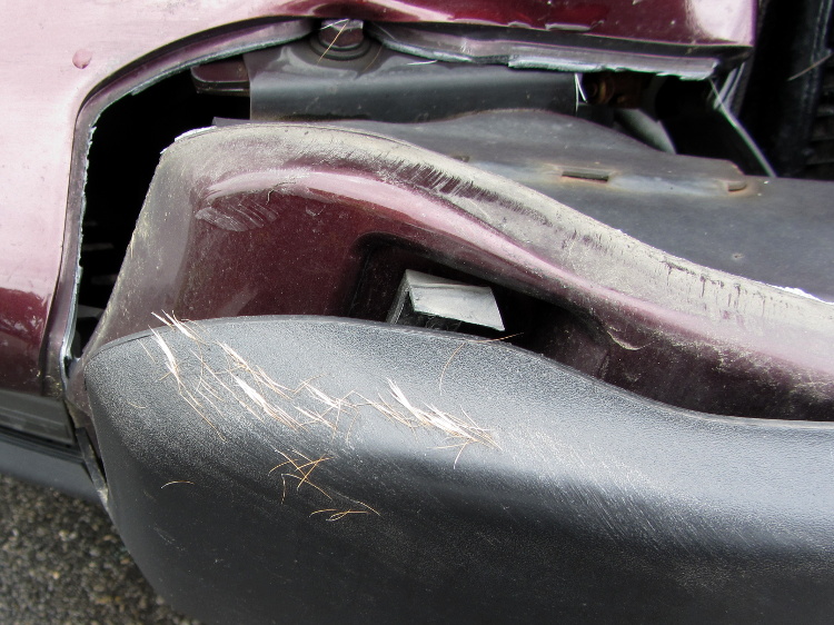
We spotted this crumpled front end at a local repair shop:
Deer crash damage – overview
A closer look at the bumper tells the tale:
Deer crash damage – hair detail
Pop Quiz: estimate the total cost of that collision, including the overhead of having to deal with the insurance company and arrange alternate transportation for a week or two.
Essay: explain why it’s possible for someone to insist that both deer and humans are better off under these conditions.
In this area, vehicles serve as the top predator for deer…
Mary’s been picking blueberries and freezing them for winter treats, a process that involves inspecting each berry laid out on the tray.
This one failed QC:
Blueberry with eggs – overview
A closer look shows some remarkable structures:
Blueberry with eggs – detail
Unfortunately, they’ll probably turn into Brown Marmorated Stink Bugs. This is not a Good Thing, because those stink bugs will devastate fruit harvests, including all the apple orchards along the entire Hudson Valley, over the next few years.
They may be Predatory Stink Bugs, which would be unusual in Dutchess County, but not nearly so awful.
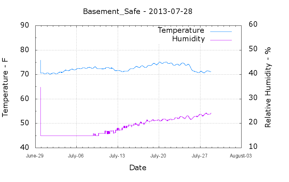
The humidity in the basement safe started rising this month:
Basement Safe – 2013-07-28
The bag of new silica gel weighed 575 g, so it adsorbed about 67 g of water as the humidity rose from bone dry to 24%. Last month it had soaked up 31 g, so the safe admits nearly an ounce of water each month with 50% RH in the basement. It takes five months to accumulate 60-ish g of water during the winter.
According to the Sorbent Systems charts, silica gel’s equilibrium capacity at 24% is about 12% of the gel’s weight, which would work out to 60 g. That’s close enough, methinks, given the graph resolution; the humidity changes slowly enough that it’s sorta-kinda equilibrated in there… 67 g works out to 13.4% of the dry weight, which is in the same ballpark.
I made up three more bags of dry gel (500 g + 7 or 8 g tare), tossed one in the safe, one in the 6 gallon plastic bucket of 3D printer filament, and one in an empty 6 gallon bucket for comparison. Some 6 dot (10-through-60%) humidity indicator cards are on their way, seeing as how I don’t have nearly enough dataloggers to keep up with the demand…
Mary just started an ambitious pieced quilt that requires 50-some-odd precisely sized 1-1/2 inch circles, with marks to locate a 1 inch circle in the middle. She started using a drafting template to mark the smaller circle on freezer paper (don’t ask, it’s complicated), but we couldn’t find the template I know I have with the larger circles.
So I says to my wife, I sez, “Hey, we have the technology. What would really simplify what you’re doing?” After a bit of doodling, we came up with a ring having the proper ID and OD, plus a flat handle of some sort.
Half an hour later, I had a solid model:
Quilting circle template – solid model
An hour after that I handed her a warm piece of plastic:
Quilting circle template
The bottom ring is exactly 1-1/2 inch OD, 1 inch ID, and thin enough to draw around. The handle keeps her fingers out of the way and even has grips and a hole for a string.
The print quality near the hole isn’t as good as I’d like, because the slicer turned that entire volume into a solid slab of plastic. I can fix that in the second version, but right now she has something to work with, evaluate, and figure out what would improve it.
3D printing isn’t for everybody, but it’s a vital part of my shop!
The OpenSCAD source code has parameters for everything, so we can crank out more templates without fuss:
// Quilting - Circle Template
// Ed Nisley KE4ZNU - July 2013

Layout = "Show";                    // Show Build Circle Handle

//-------
//- Extrusion parameters must match reality!
//  Print with 2 shells

ThreadThick = 0.25;
ThreadWidth = 0.40;

HoleFinagle = 0.2;
HoleFudge = 1.00;

function HoleAdjust(Diameter) = HoleFudge*Diameter + HoleFinagle;

Protrusion = 0.1;           // make holes end cleanly

function IntegerMultiple(Size,Unit) = Unit * ceil(Size / Unit);
function IntegerMultipleMin(Size,Unit) = Unit * floor(Size / Unit);

inch = 25.4;

//-------
// Dimensions

CircleID = (1) * inch;

SeamAllowance = (1/4) * inch;

CircleOD = CircleID + 2*SeamAllowance;

CircleThick = 6*ThreadThick;

CircleSides = 12*4;

HandleHeight = (2) * inch;
HandleThick = IntegerMultiple(5.0,ThreadWidth);
HandleSides = 12*4;

StringDia = 4.0;
StringSides = 8;
StringHeight = 0.75*HandleHeight;

DentDepth = HandleThick/4;
DentDia = 15.0;
DentSphereRadius = (pow(DentDepth,2) + pow(DentDia,2)/4)/(2*DentDepth);

//-------

module PolyCyl(Dia,Height,ForceSides=0) {           // based on nophead's polyholes
  Sides = (ForceSides != 0) ? ForceSides : (ceil(Dia) + 2);
  FixDia = Dia / cos(180/Sides);
  cylinder(r=HoleAdjust(FixDia)/2,h=Height,$fn=Sides);
}

module ShowPegGrid(Space = 10.0,Size = 1.0) {

  RangeX = floor(100 / Space);
  RangeY = floor(125 / Space);

	for (x=[-RangeX:RangeX])
	  for (y=[-RangeY:RangeY])
		translate([x*Space,y*Space,Size/2])
		  %cube(Size,center=true);

}

//-------
// Circle ring plate

module CircleRing() {

	rotate(180/CircleSides)
		difference() {
			cylinder(r=CircleOD/2,h=CircleThick,$fn=CircleSides);
			translate([0,0,-Protrusion])
				cylinder(r=CircleID/2,h=(CircleThick + 2*Protrusion),$fn=CircleSides);
		}
}

//-------
// Handle

module Handle() {

	difference() {
		rotate([0,90,0])
			scale([HandleHeight/(CircleOD/2),0.9,1])
				rotate(180/HandleSides)
					cylinder(r=CircleOD/2,h=HandleThick,center=true,$fn=HandleSides);
		translate([0,0,-HandleHeight])
			cube([2*CircleOD,2*CircleOD,2*HandleHeight],center=true);
		translate([-HandleThick,0,StringHeight])
			rotate([0,90,0])
				rotate(180/StringSides)
					PolyCyl(StringDia,2*HandleThick,StringSides);
#		for (i=[-1,1]) {
			translate([i*(DentSphereRadius + HandleThick/2 - DentDepth),0,StringHeight])
				sphere(r=DentSphereRadius);
		}
	}

}

module Template() {
	CircleRing();
	Handle();
}

//-------
// Build it!

ShowPegGrid();

if (Layout == "Circle")
	CircleRing();

if (Layout == "Handle")
	Handle();

if (Layout == "Show")
	Template();
The Stop & Shop we normally use outsources their cash register function to us; we carry a scanner around, plink each item on its way into the basket, then do a credit-card swipe on the way out. On the last trip, this popped up after I scanned the “We’re done!” barcode at the Scan It! kiosk:
Stop-and-Shop – scanner code 111
That means we were selected for a “random” audit, apparently triggered by the fact that we bought some non-typical items: ice cream! We proceeded to a nearby register, waited in line, I re-re-scanned my card, and … the whole fifteen minute process would have been a lot more amusing if said frozen items hadn’t been warming up while the harried clerk performed numerous ritual acts on the contents of our cart.
The main reason I use the scanner: there’s no other way to determine the price of any given item, what with all the unit pricing nonsense, mis-marked labels, pop-up sales, must-buy-N bundling, and so forth and so on. Secondarily, during a normal trip there’s no waiting in a lengthy queue (“Price check on Register 12!”) on the way out.
Mary hates the scanners, for well and good reason.