Ed Nisley's Blog: Shop notes, electronics, firmware, machinery, 3D printing, laser cuttery, and curiosities. Contents: 100% human thinking, 0% AI slop.
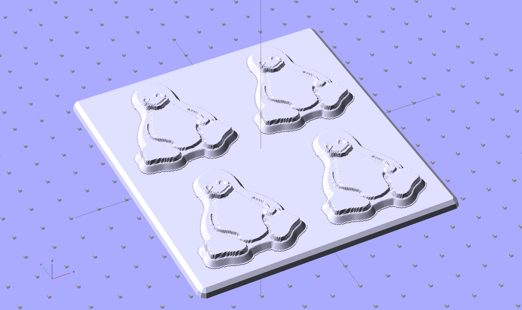
Although directly printing the 2×2 molds worked reasonably well, that does not scale to larger arrays, because OpenSCAD doesn’t handle the profusion of vertices with any grace. Duplicating the STL file created from the height map image, however, isn’t a problem:
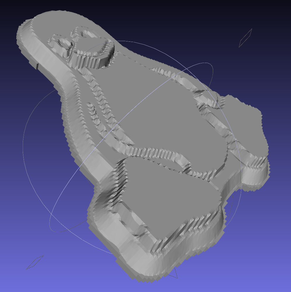
Tux-Gradient – Slic3r layout
I actually did it in two passes: 4 molds to be sure they’d come out right, then another dozen. Figure a bit under two hours for the lot of them, no matter how you, ah, slice it.
A grid drawn directly on 1/16 inch = 1.5 mm acrylic sheet guided the layout:
Tux Gradient 4×4 – mold as-cast
I anointed the back of each mold positive with PVC pipe cement, the version with tetrahydrofuran to attack the PLA and acetone/MEK to attack the acrylic, lined it up, and pressed it in place. The positives have recesses for alignment pins, but even I think that’s overkill in this application.
Memo to Self: Flip the acrylic over before gluing, so the guide lines wipe neatly off the bottom.
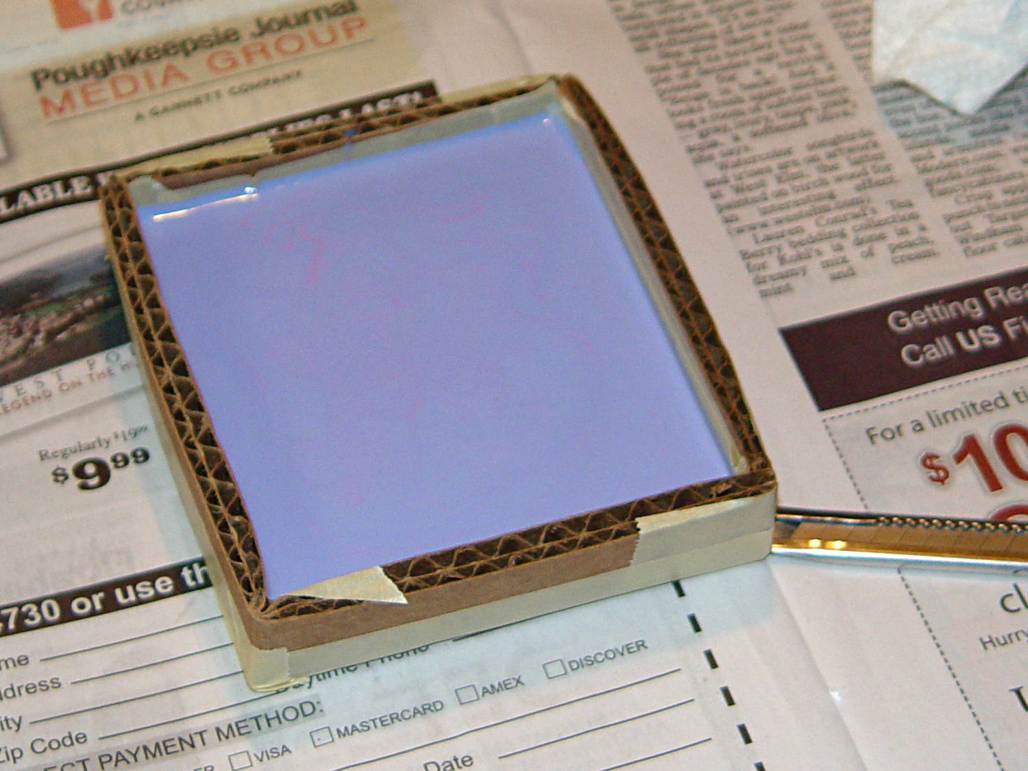
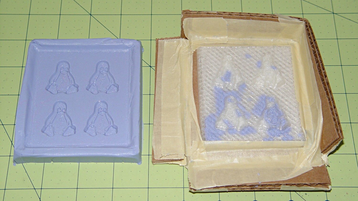
Tape a cardboard frame around the acrylic, mix & pour the silicone, put it on the floor to ensure it’s level (unlike our kitchen table), wait overnight for the cure, then peel positive and negative apart:
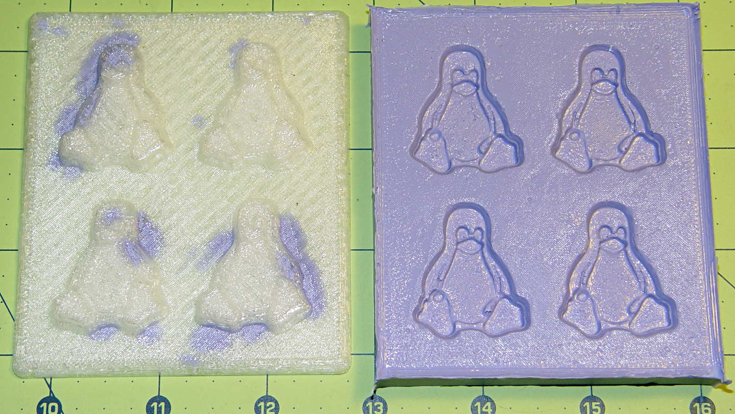
Tux Gradient 4×4 – mold separated
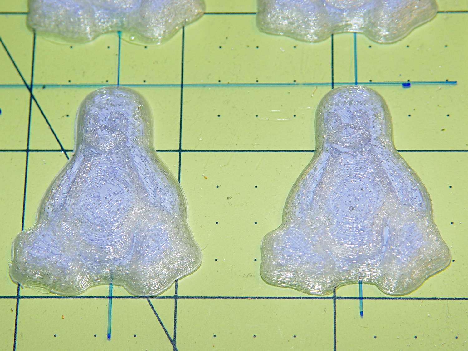
As before, the top surface of the positives isn’t watertight, so the silicone flowed through into the molds. This isn’t a simple extruder calibration issue, because the thinwall boxes are spot on, all the exterior dimensions are accurate, and everything else seems OK. What’s not OK is that threads on the top and (now that I look at it) bottom surfaces aren’t properly joining.
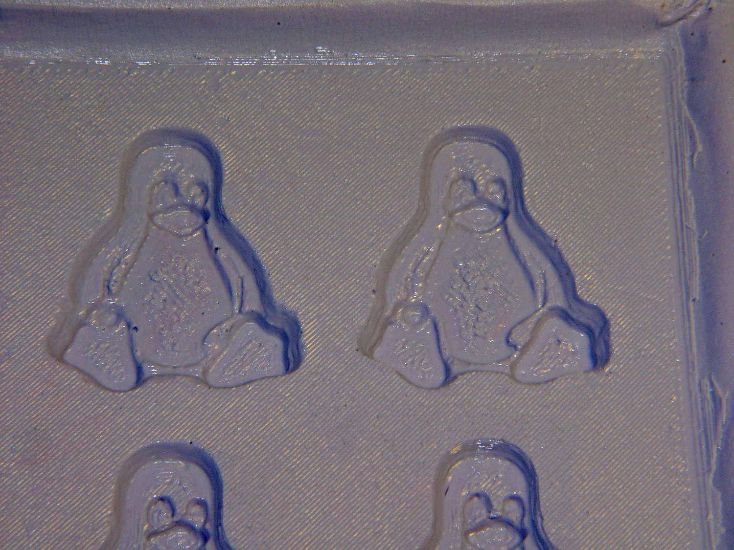
A closeup of the positive shows silicone between the threads and under the surface:
Tux Gradient 4×4 – postive detail
But the negative silicone looks just fine, in the usual hand-knitted way of all 3D printed parts:
Tux Gradient 4×4 – negative detail
Definitely fewer bubbles than before, although the flange between the flippers (wings? whatever) and the body isn’t as clean as it could be. Doing better may require pulling a vacuum on the silicone, which would mean the positives really must be air-tight solids.
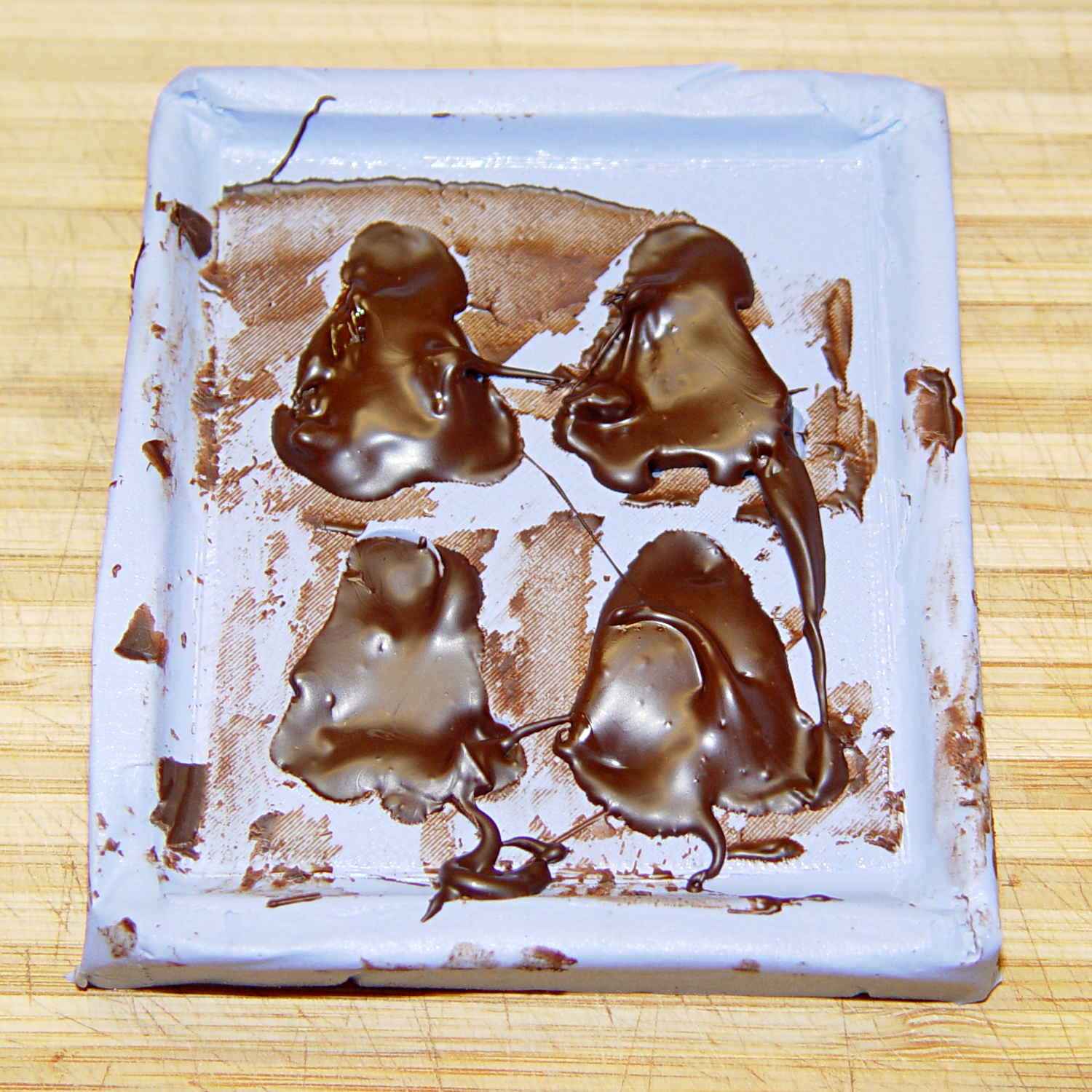
Anyhow, the acrylic base produced a wonderfully flat surface that should make it a lot easier to run a scraper across the chocolate to remove the excess. Not that excess chocolate is ever a problem, but it’s the principle of the thing.
A rough estimate of the volume and measurement thereof:
Assume 1 cm slab thickness for mold cavities 4 or 5 mm deep
Measure size of base plate in cm (given by OpenSCAD script in mm)
Compute slab volume in cubic cm = millliliters (ignoring mold cavity volumes)
Divide by 2 to find volume of each silicone component
Mark that volume on the side of two sacrificial containers
Pour silicone components into those containers
Pour one into the other, mix twice as long as you think you should
Scrupulously avoid cross-contaminating the original containers!
Fast-forward overnight, cut the tape, and peel the silicone negative off the positive:
Tux 2×2 mold – opened
The top surface of the 3D printed positive wasn’t completely water silicone-tight, so the silicone leaked through the top and filled part of the interior. No harm done, but I wasn’t expecting that. The interior of the silicone negative came out pretty well, although you can see some small bubble cavities that may be due to air leaking out through the top of the positive:
Tux 2×2 mold – negative detail
The hand-knitted texture of the 3D printing process comes through very well, which is a Good Thing in this application. If you don’t like that, you can devote considerable time & attention to removing all traces of the production process.
As a proof of concept, I melted and tempered four Dove Dark Chocolate Promises, then poured the chocolate into the cavities:
Tux 2×2 mold – filled
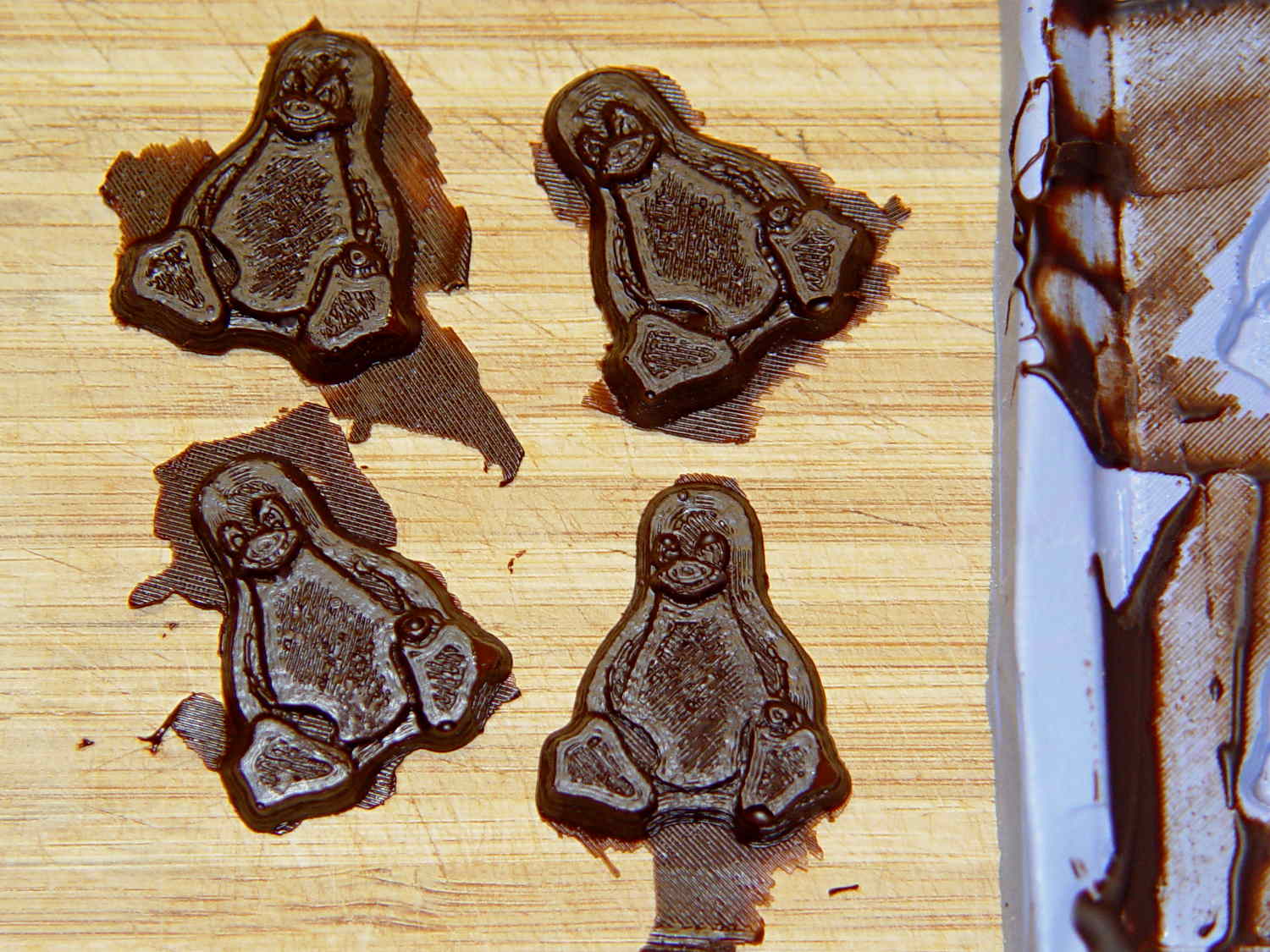
The tempering followed a fairly simple process that worked reasonably well, but the chocolate obviously wasn’t liquid when I poured it. The results looked pretty good, in a textured sort of way:
Tux chocolates – silicone mold
Flushed with success, I tweaked the mold to eliminate the raised lip around the edge, printed another positive plate, mixed up more silicone rubber, paid more attention to getting rid of the bubbles, and got this result:
Tux 2×2 mold 2 – opened
The printed surface still isn’t silicone-tight, which began to puzzle me, but the result looked pretty good.
After some fiddling around, though, I think printing the entire mold array isn’t the way to go. OpenSCAD can handle these 2×2 arrays, but a slightly tweaked Tux model (about which, more later) grossly increased the processing time and memory usage; OpenSCAD (and its CGAL geometry back end) filled all 4 GB of RAM, then blotted up 5 GB of swap space, ran for well over half an hour, and totally locked up the desktop UI for the duration.
It’s certainly infeasible to print the larger array on a sizable base plate that you’d need for a real project. I think printing multiple copies of a single model (duplicating them in the slicer, which is fast & easy), then attaching them to a plain base will work better. There’s no need to print the base plate, either, as a serrated top surface doesn’t buy anything; acrylic (or some such) sheet is cheap, flat, and readily available.
The Bash scripts and OpenSCAD programs below don’t produce exactly the same results you see above, mostly because I screwed around with them while discovering the reasons why doing it this way doesn’t make sense, but they can serve as a starting point if you must convince yourself, too.
This Bash script produces a single positive mold item from a height map image:
// Mold positive pattern from grayscale height map
// Ed Nisley KE4ZNU - March 2014 - adapted from cookie press, added alignment pins

//-----------------
// Mold files

fnMap = "Tux_map.dat";					// override with -D 'fnMap="whatever.dat"'
fnPlate = "Tux_plate.dat";				// override with -D 'fnPlate="whatever.dat"'

DotsPerMM = 3.0;						// overrride with -D DotsPerMM=number

MapHeight = 4.0;						// overrride with -D MapHeight=number

ImageX = 100;							// overrride with -D ImageX=whatever
ImageY = 100;

UsePins = true;

MapScaleXYZ = [1/DotsPerMM,1/DotsPerMM,MapHeight/255];
PlateScaleXYZ = [1/DotsPerMM,1/DotsPerMM,1.0];

echo("Press File: ",fnMap);
echo("Plate File: ",fnPlate);

echo(str("ImageX:",ImageX," ImageY: ", ImageY));
echo(str("Map Height: ",MapHeight));
echo(str("Dots/mm: ",DotsPerMM));
echo(str("Scale Map: ",MapScaleXYZ,"  Plate: ",PlateScaleXYZ));

//- Extrusion parameters - must match reality!

ThreadThick = 0.25;
ThreadWidth = 2.0 * ThreadThick;

//- Buid parameters

PlateThick = IntegerMultiple(1.0,ThreadThick);		// solid plate under press relief

PinOD = 1.75;				// locating pin diameter
PinDepth = PlateThick;		//  ... depth into bottom surface = total length/2
PinOC = 20.0;				// spacing within mold item

echo(str("Pin depth: ",PinDepth," spacing: ",PinOC));

//- Useful info

function IntegerMultiple(Size,Unit) = Unit * ceil(Size / Unit);

HoleWindage = 0.2;

Protrusion = 0.1;						// make holes & unions work correctly

MaxConvexity = 5;						// used for F5 previews in OpenSCAD GUI

ZFuzz = 0.2;							// numeric chaff just above height map Z=0 plane

//-----------------
// Import plate height map, slice off a slab to define outline

module Slab(Thick=1.0) {
	intersection() {
		translate([0,0,Thick/2])
			cube([2*ImageX,2*ImageY,Thick],center=true);
		scale(PlateScaleXYZ)
			difference() {
				translate([0,0,-ZFuzz])
					surface(fnPlate,center=true,convexity=MaxConvexity);
				translate([0,0,-1])
					cube([2*ImageX,2*ImageY,2],center=true);
			}
	}
}

//- Put peg grid on build surface

module ShowPegGrid(Space = 10.0,Size = 1.0) {

	Range = floor(50 / Space);

	for (x=[-Range:Range])
	  for (y=[-Range:Range])
		translate([x*Space,y*Space,Size/2])
			%cube(Size,center=true);
}

//-- convert cylinder to low-count polygon

module PolyCyl(Dia,Height,ForceSides=0) {			// based on nophead's polyholes

  Sides = (ForceSides != 0) ? ForceSides : (ceil(Dia) + 2);

  FixDia = Dia / cos(180/Sides);

  cylinder(r=(FixDia + HoleWindage)/2,
           h=Height,
	   $fn=Sides);
}

//-- Locating pin hole with glue recess
//  Default length is two pin diameters on each side of the split

module LocatingPin(Dia=PinOD,Len=0.0) {

	PinLen = (Len != 0.0) ? Len : (4*Dia);

	translate([0,0,-ThreadThick])
		PolyCyl((Dia + 2*ThreadWidth),2*ThreadThick,4);

	translate([0,0,-2*ThreadThick])
		PolyCyl((Dia + 1*ThreadWidth),4*ThreadThick,4);

	translate([0,0,-(Len/2 + ThreadThick)])
		PolyCyl(Dia,(Len + 2*ThreadThick),4);

}

//- Build it

//ShowPegGrid();

echo("Building mold");
union() {
	difference() {
		Slab(PlateThick + Protrusion);
		if (UsePins)
			for (i=[-1,1])
				translate([0,i*PinOC/2,0])
					rotate(180/4) LocatingPin(Len=2*PinDepth);
	}
	translate([0,0,PlateThick])							// cookie press height map
		scale(MapScaleXYZ)
		difference() {
			translate([0,0,-ZFuzz])
				surface(fnMap,center=true,convexity=MaxConvexity);
			translate([0,0,-1])
				cube([2*ImageX,2*ImageY,2],center=true);
		}
}
This OpenSCAD source code slides a base plate under an array of those mold items, with options for a separate plate using alignment pins or the combined plate-with-molds shown above:
// Positive mold framework for chocolate slabs
// Ed Nisley - KE4ZNU - March 2014

Layout = "FrameMolds";		// FramePins FrameMolds Pin

//- Extrusion parameters must match reality!
//  Print with 2 shells and 3 solid layers

ThreadThick = 0.20;
ThreadWidth = 0.40;

Protrusion = 0.1;			// make holes end cleanly

HoleWindage = 0.2;

//----------------------
// Dimensions

FileName = "Tux_Hi_Profile-positive.stl";	// overrride with -D

Molds = [2,2];					// count of molds within framework

MoldOC = [45.0,50.0];			// on-center spacing of molds
MoldSlab = 1.0;					// thickness of slab under molds

BaseThick = 3.0;

BaseSize = [(Molds[0]*MoldOC[0] + 0),(Molds[1]*MoldOC[1] + 0),BaseThick];
echo(str("Overall base: ",BaseSize));

PinOD = 1.75;					// locating pin diameter
PinLength = 2.0;				//  ... total length
PinOC = 20.0;				// spacing within mold item

//----------------------
// Useful routines

//- Put peg grid on build surface

module ShowPegGrid(Space = 10.0,Size = 1.0) {

	RangeX = floor(100 / Space);
	RangeY = floor(125 / Space);

	for (x=[-RangeX:RangeX])
		for (y=[-RangeY:RangeY])
			translate([x*Space,y*Space,Size/2])
			%cube(Size,center=true);

}

module PolyCyl(Dia,Height,ForceSides=0) {			// based on nophead's polyholes

  Sides = (ForceSides != 0) ? ForceSides : (ceil(Dia) + 2);

  FixDia = Dia / cos(180/Sides);

  cylinder(r=(FixDia + HoleWindage)/2,
           h=Height,
	   $fn=Sides);
}

// Locating pin hole with glue recess
//  Default length is two pin diameters on each side of the split

module LocatingPin(Dia=PinOD,Len=0.0) {

	PinLen = (Len != 0.0) ? Len : (4*Dia);

	translate([0,0,-ThreadThick])
		PolyCyl((Dia + 2*ThreadWidth),2*ThreadThick,4);

	translate([0,0,-2*ThreadThick])
		PolyCyl((Dia + 1*ThreadWidth),4*ThreadThick,4);

	translate([0,0,-(Len/2 + ThreadThick)])
		PolyCyl(Dia,(Len + 2*ThreadThick),4);

}

module LocatingPins(Length) {
	for (i=[-1,1])
	translate([0,i*PinOC/2,0])
		rotate(180/4)
		LocatingPin(Len=Length);
}

//-- import a single mold item

module MoldItem() {

//	intersection() {
		import(FileName,convexity=10);
//		cube([100,100,3],center=true);
//	}
}

//-- Overall frame shape

module Frame() {

//	translate([0,0,BaseSize[2]/2])		// platform under molds
//		cube(BaseSize,center=true);

	difference() {
		hull()
			for (i=[-1,1], j=[-1,1])
				translate([i*BaseSize[0]/2,j*BaseSize[1]/2,0])
					sphere(r=BaseThick);
		translate([0,0,-BaseThick])
			cube(2*BaseSize,center=true);
	}

}

//- Build it

ShowPegGrid();

if (Layout == "Pin")
	LocatingPin(Len=PinLength);

if (Layout == "Frame")
	Frame();

if (Layout == "FramePins")
	difference() {
		Frame();

		translate([-MoldOC[0]*(Molds[0] - 1)/2,-MoldOC[1]*(Molds[1] - 1)/2,0])
			for (i=[0:Molds[0]-1],j=[0:Molds[1]-1])
				translate([i*MoldOC[0],j*MoldOC[1],BaseSize[2]])
					LocatingPins(BaseThick);
	}

if (Layout == "FrameMolds") {
	Frame();
	translate([-MoldOC[0]*(Molds[0] - 1)/2,-MoldOC[1]*(Molds[1] - 1)/2,0])
		for (i=[0:Molds[0]-1],j=[0:Molds[1]-1])
			translate([i*MoldOC[0],j*MoldOC[1],BaseThick - MoldSlab + Protrusion])
			MoldItem();
}
Natural PLA provides a nice, crystalline appearance:
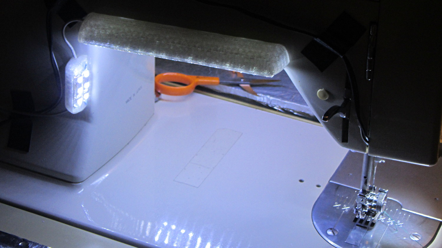
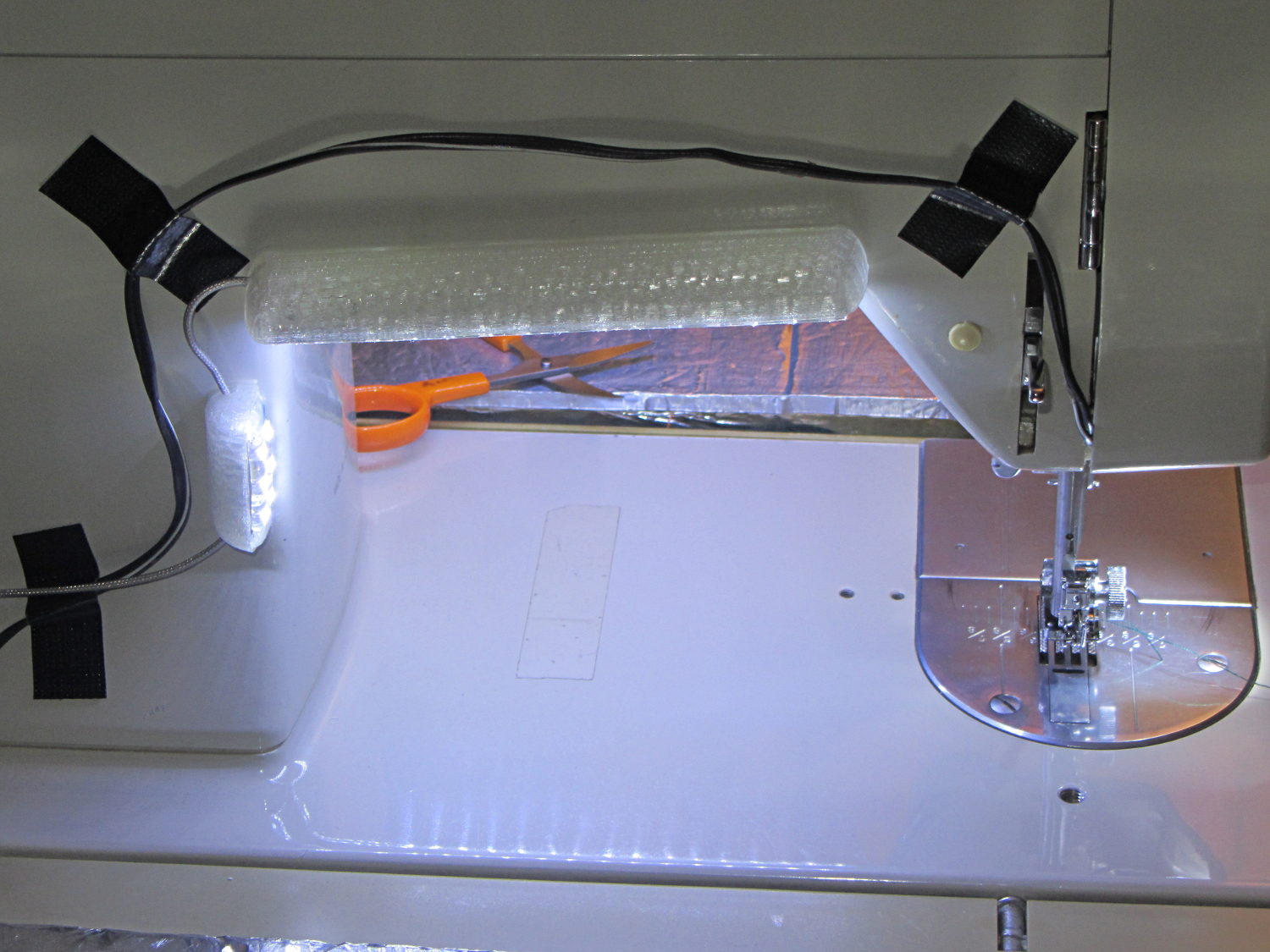
Kenmore 158 Sewing Machine – Cool white LEDs – rear no flash
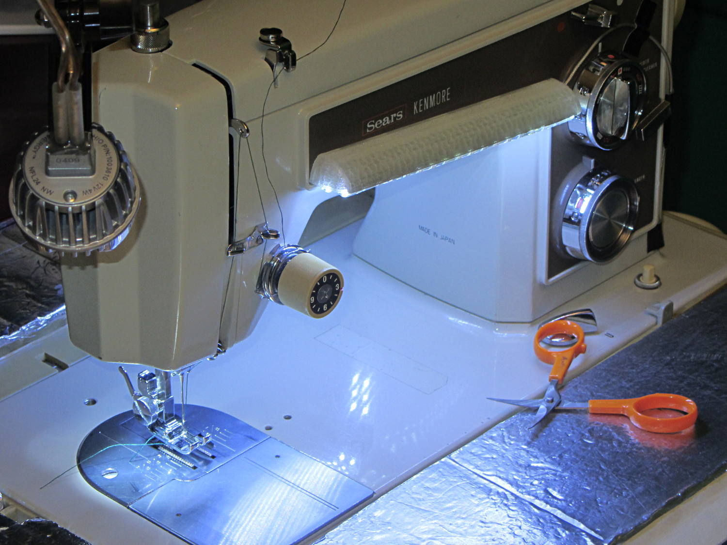
Cool white LEDs have somewhat higher lumen/watt efficiency, but the real gain came from doubling the number of LEDs:
Kenmore 158 Sewing Machine – Cool white LEDs – front flash
I overvolted the warm white LEDs to 14 V to get closer to 20 mA/segment, but the cool white ones run pretty close to 20 mA at 12 V, so I didn’t bother.
Commercial versions of this hack secure the wiring with little white clips and foam tape, so I should conjure up something like that. Mary specifically did not want the lights affixed under the arm, though, so those things weren’t even in the running.
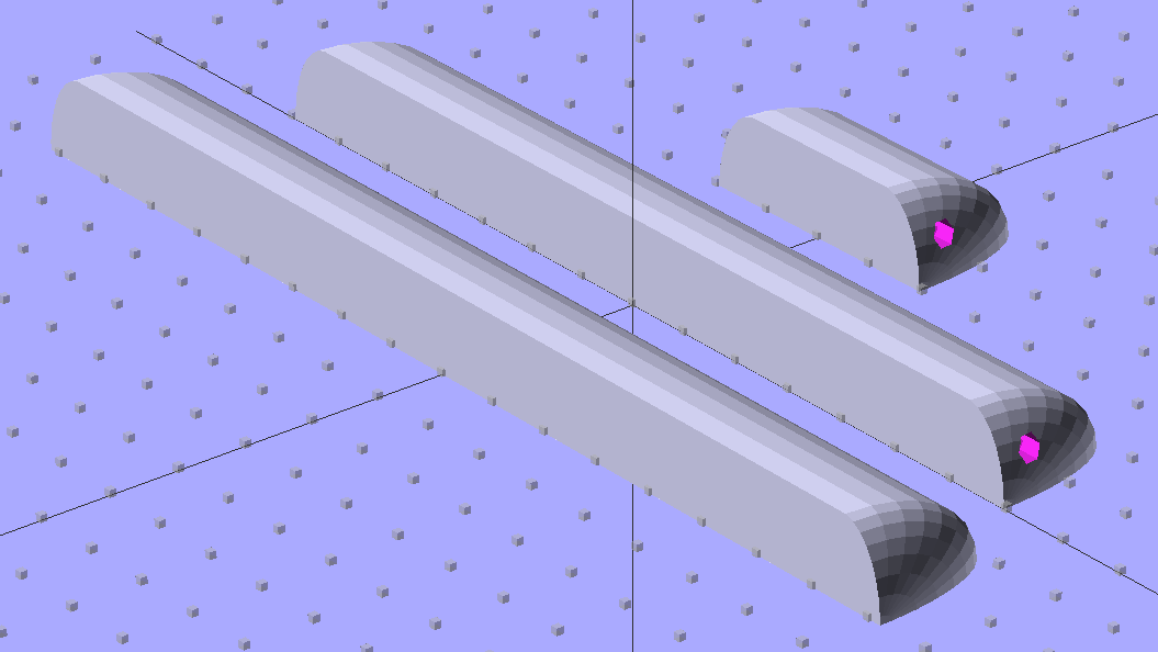
The OpenSCAD source code widens the mount and moves the wiring conduit a little bit, to simplify the connections to both strips, but is otherwise identical to the earlier version:
// LED Strip Lighting Brackets for Kenmore Model 158 Sewing Machine
// Ed Nisley - KE4ZNU - March 2014

Layout = "Build";			// Build Show Channels Strip

//- Extrusion parameters must match reality!
//  Print with 2 shells and 3 solid layers

ThreadThick = 0.20;
ThreadWidth = 0.40;

HoleWindage = 0.2;			// extra clearance

Protrusion = 0.1;			// make holes end cleanly

AlignPinOD = 1.70;			// assembly alignment pins: filament dia

inch = 25.4;

function IntegerMultiple(Size,Unit) = Unit * ceil(Size / Unit);

//----------------------
// Dimensions

Segment = [25.0,10.0,3.0];		//  size of each LED segment
SEGLENGTH = 0;
SEGWIDTH = 1;
SEGHEIGHT = 2;

WireChannel = 3.0;				// wire routing channel

StripHeight = 12.0;				// sticky tape width
StripSides = 8*4;

DefaultLayout = [1,2,"Wire","NoWire"];
NUMSEGS = 0;
NUMSTRIPS = 1;
WIRELEFT = 2;
WIRERIGHT = 3;

EndCapSides = StripSides;

CapSpace = 2.0;						// build spacing for endcaps
BuildSpace = 3.0;					// spacing between objects on platform

//----------------------
// Useful routines

module PolyCyl(Dia,Height,ForceSides=0) {			// based on nophead's polyholes

  Sides = (ForceSides != 0) ? ForceSides : (ceil(Dia) + 2);

  FixDia = Dia / cos(180/Sides);

  cylinder(r=(FixDia + HoleWindage)/2,
           h=Height,
           $fn=Sides);
}

module ShowPegGrid(Space = 10.0,Size = 1.0) {

  RangeX = floor(100 / Space);
  RangeY = floor(125 / Space);

	for (x=[-RangeX:RangeX])
	  for (y=[-RangeY:RangeY])
		translate([x*Space,y*Space,Size/2])
		  %cube(Size,center=true);

}

//-- The negative space used to thread wires into the endcap

module MakeWireChannel(Layout = DefaultLayout,Which = "Left") {

	EndCap = [(2*WireChannel + 1.0),Layout[NUMSTRIPS]*Segment[SEGWIDTH],StripHeight];	// radii of end cap spheroid

	HalfSpace = EndCap[0] * ((Which == "Left") ? 1 : -1);

	render(convexity=2)
	translate([0,Segment[SEGWIDTH]/2,0])
		intersection() {
			union() {
				cube([2*WireChannel,WireChannel,EndCap[2]],center=true);
				translate([-2*EndCap[0],0,EndCap[2]/2])
					rotate([0,90,0]) rotate(180/6)
						PolyCyl(WireChannel,4*EndCap[0],6);
			}
			translate([HalfSpace,0,(EndCap[2] - Protrusion)]) {
				cube(2*EndCap,center=true);
			}
		}
}

//-- The whole strip, minus wiring channels

module MakeStrip(Layout = DefaultLayout) {

	EndCap = [(2*WireChannel + 1.0),Layout[NUMSTRIPS]*Segment[SEGWIDTH],StripHeight];	// radii of end cap spheroid

	BarLength = Layout[NUMSEGS] * Segment[SEGLENGTH];				// central bar length

	hull()
		difference() {
			for (x = [-1,1])						// endcaps as spheroids
				translate([x*BarLength/2,0,0])
					resize(2*EndCap) rotate([0,90,0]) sphere(1.0,$fn=EndCapSides);
			translate([0,0,-EndCap[2]])
				cube([2*BarLength,3*EndCap[1],2*EndCap[2]],center=true);
			translate([0,-EndCap[1],0])
				cube([2*BarLength,2*EndCap[1],3*EndCap[2]],center=true);
		}

}

//-- Cut wiring channels out of strip

module MakeMount(Layout = DefaultLayout) {

	BarLength = Layout[NUMSEGS] * Segment[SEGLENGTH];

	difference() {
		MakeStrip(Layout);
		if (Layout[WIRELEFT] == "Wire")
			translate([BarLength/2,0,0])
				MakeWireChannel(Layout,"Left");
		if (Layout[WIRERIGHT] == "Wire")
			translate([-BarLength/2,0,0])
				MakeWireChannel(Layout,"Right");
	}
}

//- Build it

ShowPegGrid();

if (Layout == "Channels") {
	translate([ (2*WireChannel + 1.0),0,0]) MakeWireChannel(DefaultLayout,"Left");
	translate([-(2*WireChannel + 1.0),0,0]) MakeWireChannel(DefaultLayout,"Right");
}

if (Layout == "Strip") {
	MakeStrip(DefaultLayout);
}

if (Layout == "Show") {
	MakeMount(DefaultLayout);
}

if (Layout == "Build") {

	translate([0,(3*Segment[SEGWIDTH]),0]) MakeMount([1,2,"Wire","Wire"]);		// rear left side, vertical
	translate([0,0,0]) MakeMount([5,2,"Wire","NoWire"]);				// rear top, across arm
	translate([0,-(3*Segment[SEGWIDTH]),0]) MakeMount([6,2,"NoWire","Wire"]);	// front top, across arm
}
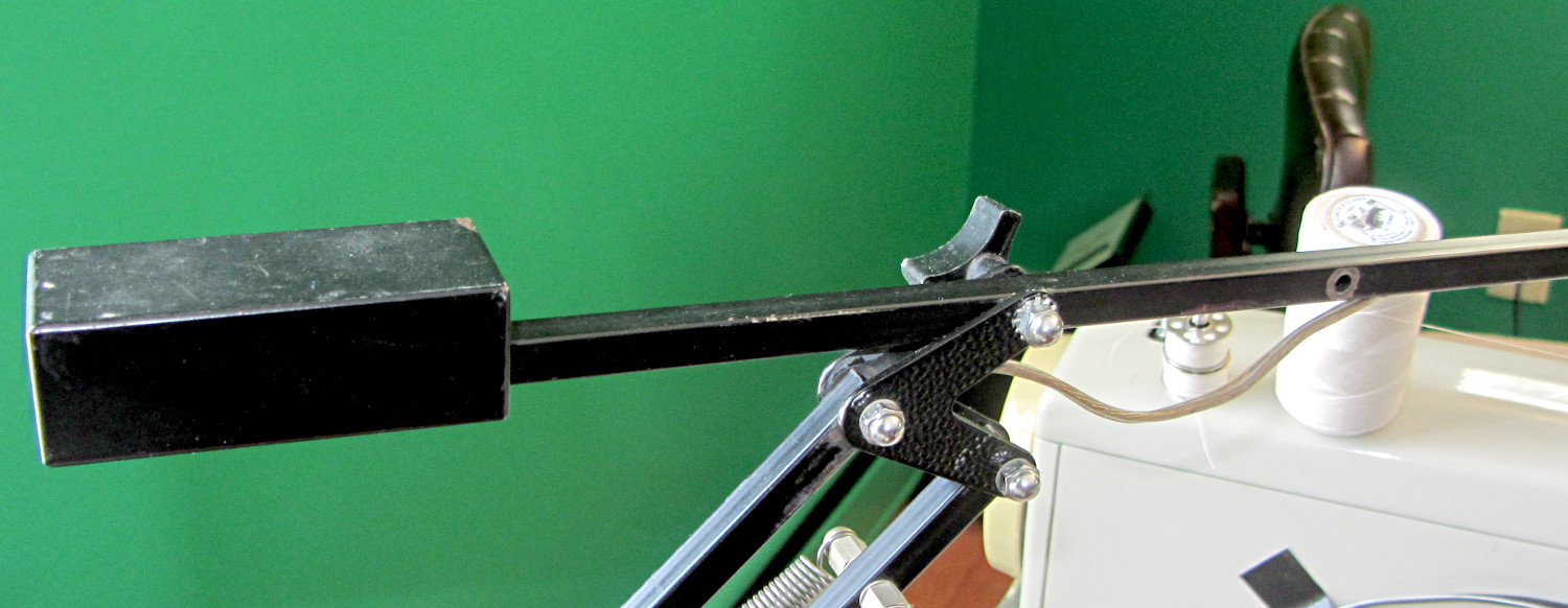
Moving the pivot point of the rebuilt desk lamp arm back about 75 mm put it at the proper spot:
Rebalanced desk lamp boom
That required snaking new wiring from the transformer in the base through the upright and out through the boom to the LED floodlamp. I used a random length of speaker cable from the Big Box o’ Heavy Wires, although it doesn’t take much to carry 300 mA at 12 V.
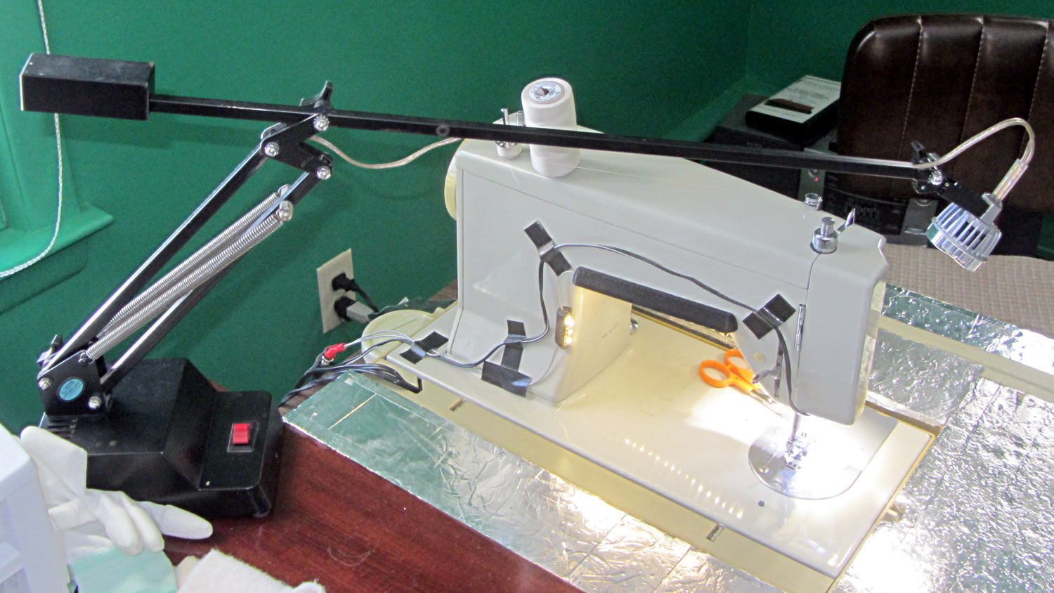
The lamp head now reaches the work area and the base stays out of the way:
Rebuild desk lamp over sewing machine
It is, we both agree, hideously ugly, but it puts plenty of light at the right spot.
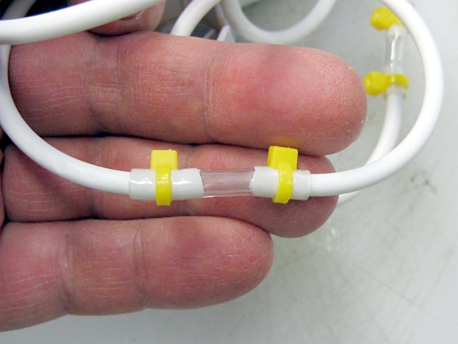
It seems the coiled hose on “water flossers” or “water jet” oral hygene appliances (I can’t even type that with a straight face) lasts about three years, then fails in a spectacular water spray. Mary’s Interplak cleaner just blew a hose, whereupon I discovered that 3/32 inch ID Tygon tubing is a very snug press fit over the 3.8 mm OD white plastic hose:
Patched Interplak tubing
The hose blew out during the early part of a protracted snow storm / cold snap, when driving out for a replacement wasn’t going to happen. This fix, ugly though it may be, has been working well enough that we’ll wait for something else to go wrong.
It’s not clear replacing the entire length of hose with Tygon tubing would work as well, because the rigid hose transmits water pressure pulses from the pump to the tip without much damping. We’re not sure how much that matters and, if the Tygon hack outlasts the OEM hose, maybe we’ll try that.
As you might expect, the hose isn’t a replaceable part. In fact, Interplak doesn’t list any replaceable parts, other than the jet tips, which never seem to wear out…
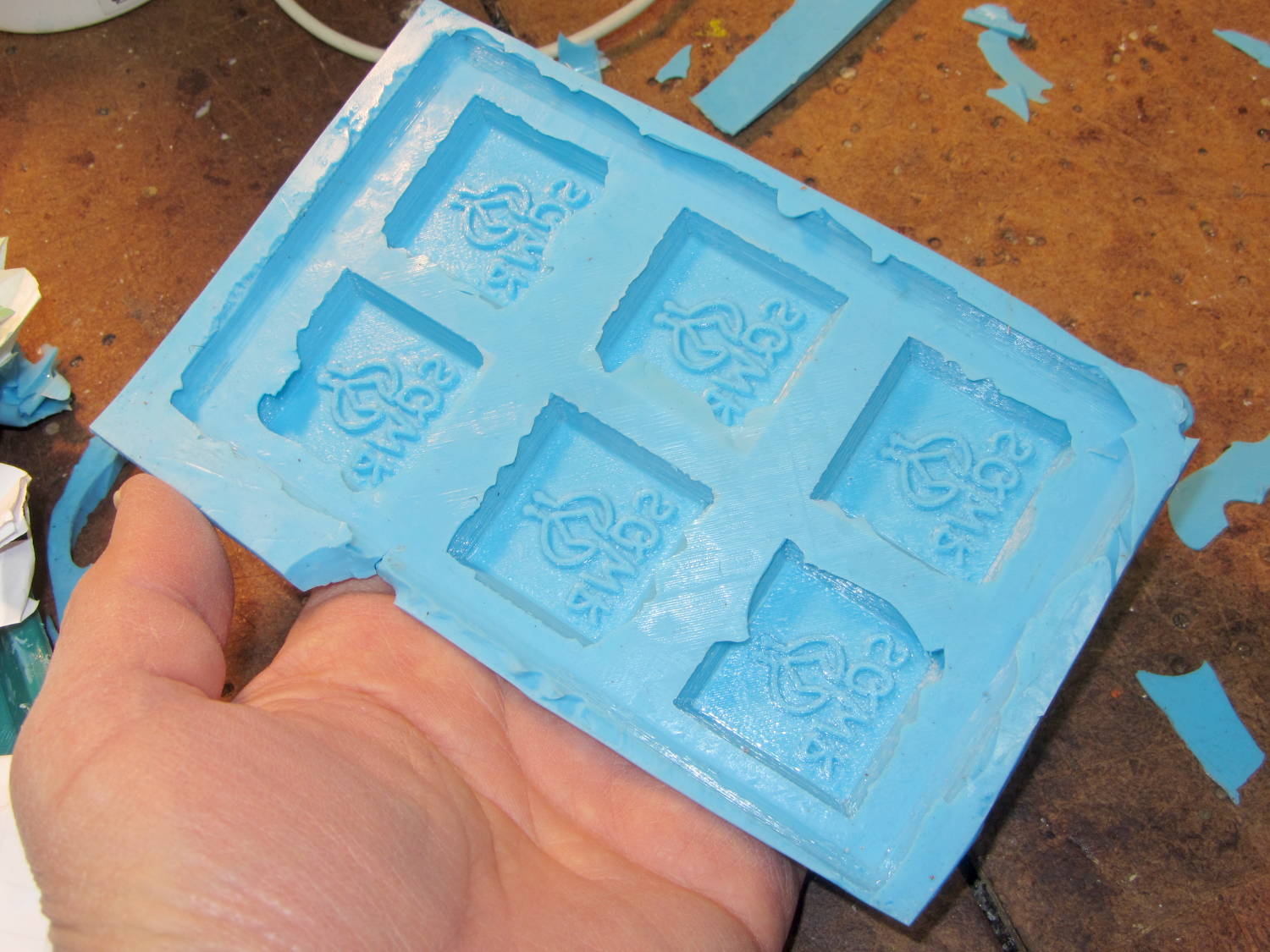
A closeup shows that the characteristic 3D printed striations came through perfectly on the silicone:
SqWr chocolate molds – silicone interior detail
In this application, the 3D printer’s hand-knitted look is desirable, but most molds would benefit from manual smoothing / sanding / filling; perhaps slathering release agent over the molds would help. In any event, the silicone didn’t lock to the striations and parted easily, so it’s all good.
The first layer of silicone worked its way between the positive molds and the slab; Tesa says the positives were so well attached to the pegs that she forgot to apply double-sided tape between them. No harm done: the flashing peeled / trimmed off easily enough.
She thinks a shallow block mold would work just as well for a slab like this: you’d (well, she’d) save hours of tedious layering. The block mold wouldn’t use any more silicone, as the mixing cup had plenty of residue after each layer, even after scraping: doing just one mixing, one pouring, and one curing stage would be a major win.