Ed Nisley's Blog: Shop notes, electronics, firmware, machinery, 3D printing, laser cuttery, and curiosities. Contents: 100% human thinking, 0% AI slop.
An email discussion suggested the Champion hose nozzle might, once upon a time, have had a washer between the conical and cylindrical sections.
So I made one:
Champion hose nozzle – rubber washer
The details:
OD = ½ inch
ID = 9/32 inch
2.5 mm stamp pad rubber
It sealed perfectly, but, just before shutting off, the washer vibrated in the water flow and gave off an ear-shattering (even to my deflicted hearing) howl.
Perhaps a stiffer and thinner washer with a slightly larger OD would work better.
A quick check of similar nozzles in the Box o’ Hydraulics shows none of them feel like they have a compliant washer in there, but any sufficiently old rubber will have long since fossilized.
This seems like a good job for a 3D printed washer with a conical face, made from slightly squishy TPU plastic to ease it past the nozzle’s internal threads. All I need is the ability to print TPU …
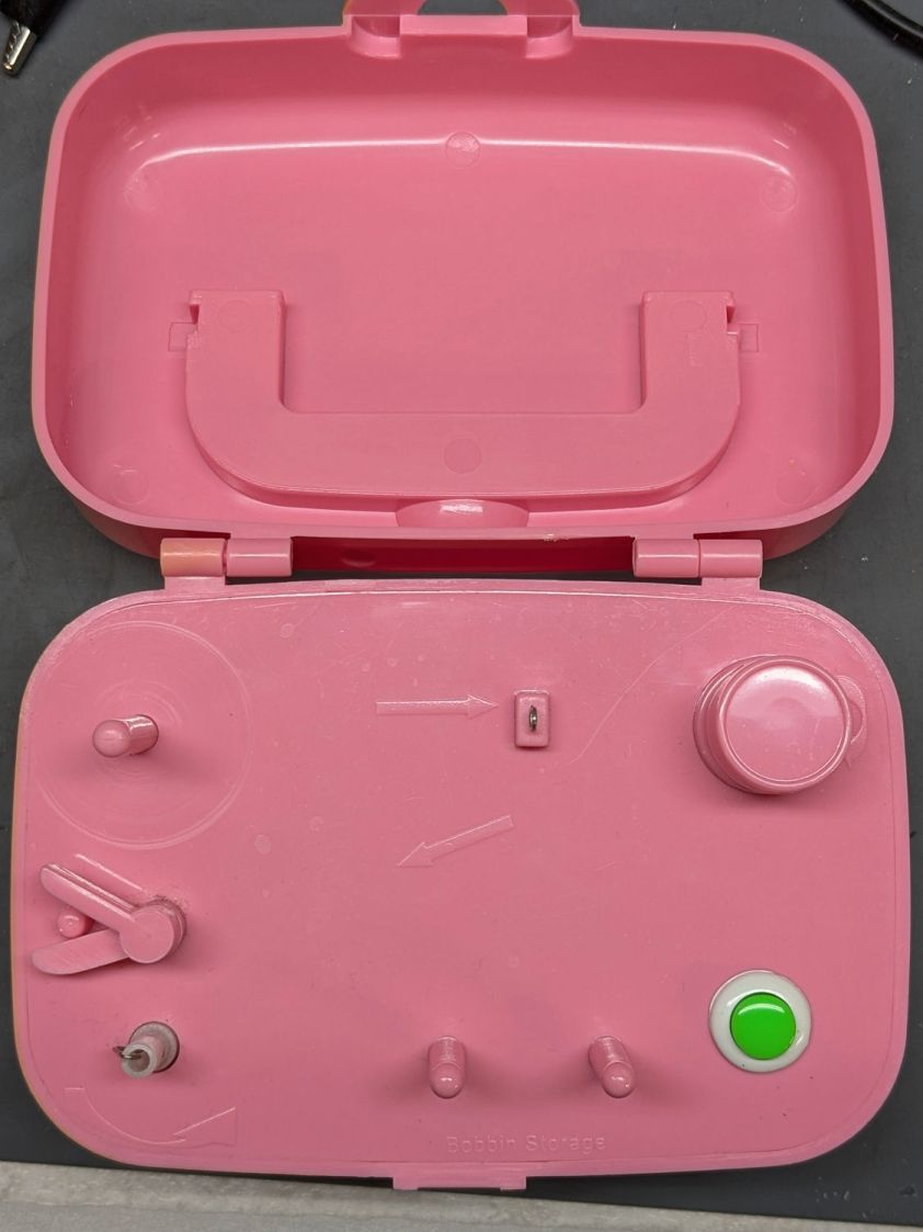
The HQ Sixteen has much larger bobbins than Mary’s Kenmore and Juki sewing machines. It also came with a dedicated bobbin winder:
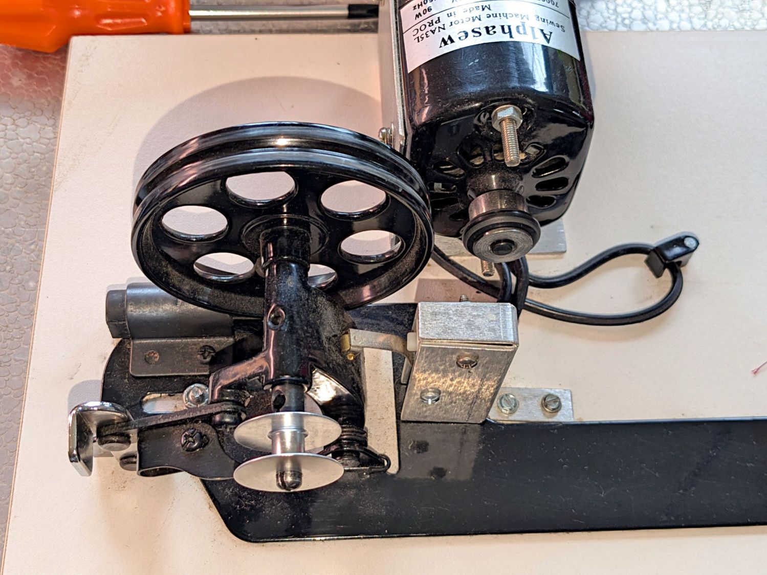
HQ Sixteen bobbin winder – overview
That thing has a distinct Industrial Revolution aspect compared to the BarbieCore bobbin winder I laid hands on a while ago.
Out of the photo on the right:
The thread cone and guide tower
The thread tension disks
Mary had been having trouble winding the bobbins, as the tension seemed entirely too low and the thread did not lay smoothly across the bobbin, so she asked me to take a look.
The motor shaft has an O-ring for friction drive against the large wheel driving the shaft with the bobbin on the other end. The small silver lever over on the left flips an over-center lock pressing the wheel against the O-ring and tripping the microswitch in the aluminum housing, thus turning the motor on. The bobbin fills until a small finger monitoring the thread level flips the lock back over center, the wheel disengages, the switch turns the motor off, and a spring drives the wheel against the rubber rod in the upper left.
Which worked well, but all the bobbins had a loose-to-sloppy fit on the shaft, to the extent that the shaft really couldn’t drive them against any thread tension.
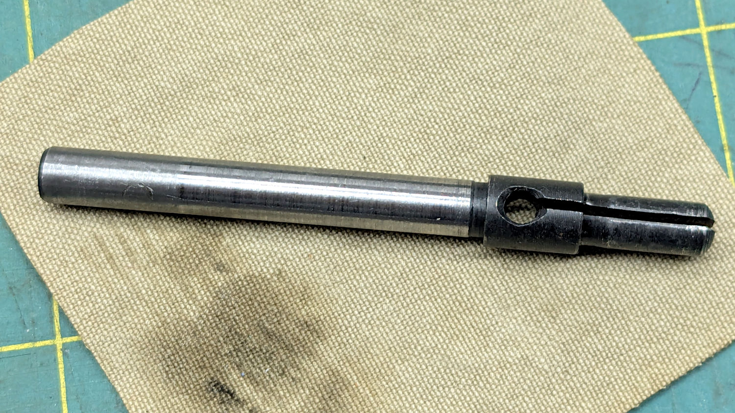
Loosening the screw holding the drive wheel on the shaft lets it slip off and the shaft slides out to the front:
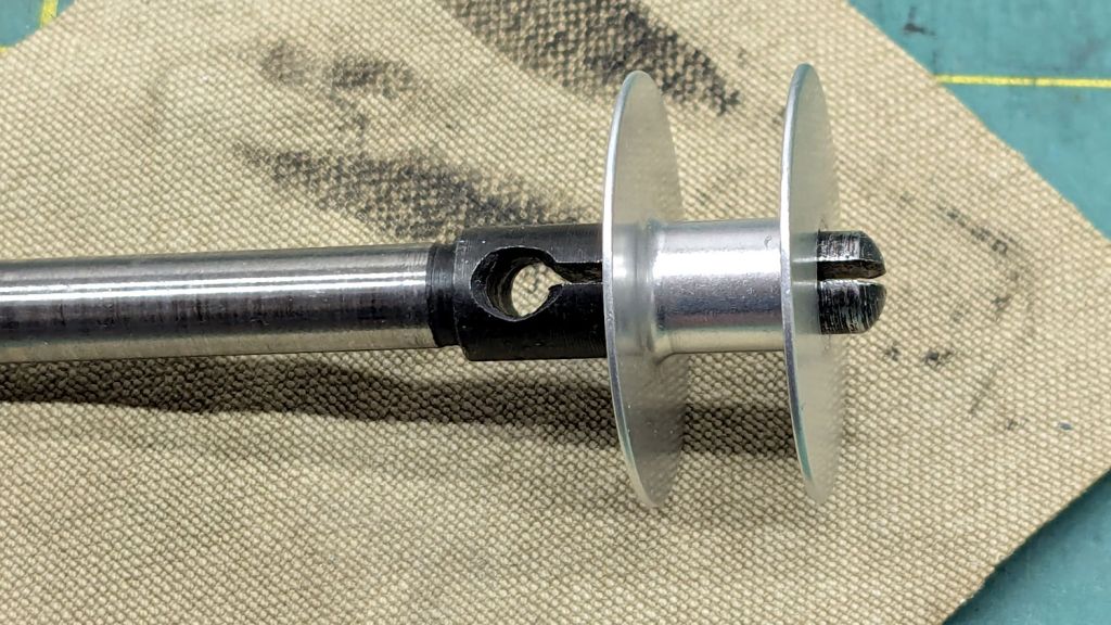
HQ Sixteen bobbin winder – split shaft
The sides of the split shaft should press firmly against the bobbin core, but that just wasn’t happening.
Measuring a dozen bobbins showed most had an ID of 6.04 mm, with a few around 6.01 mm; unsurprisingly, the latter had the best, albeit still loose, fit. Conversely, the split shaft had two isolated points 6.01 mm apart across a diameter, with the remainder around 5.95 mm. Those are not large differences, but it was obvious why the bobbins didn’t wind correctly.
I filed some graunch off the split edges, then gently pushed the Designated Prydriver into the end of the split to spread the sides juuuust a little bit, until all the bobbins pushed on firmly and fit snugly:
HQ Sixteen bobbin winder – split shaft test fit
It reassembled in reverse order and we’ll see how it behaves during the next marathon bobbin-filling session.
Trace the outlines and lay smooth curves around them with Inkscape:
Remote profiles – Inkscape curves
They needed a slight lengthening to account for the gauge pin diameter & deflection, but this isn’t a precision project.
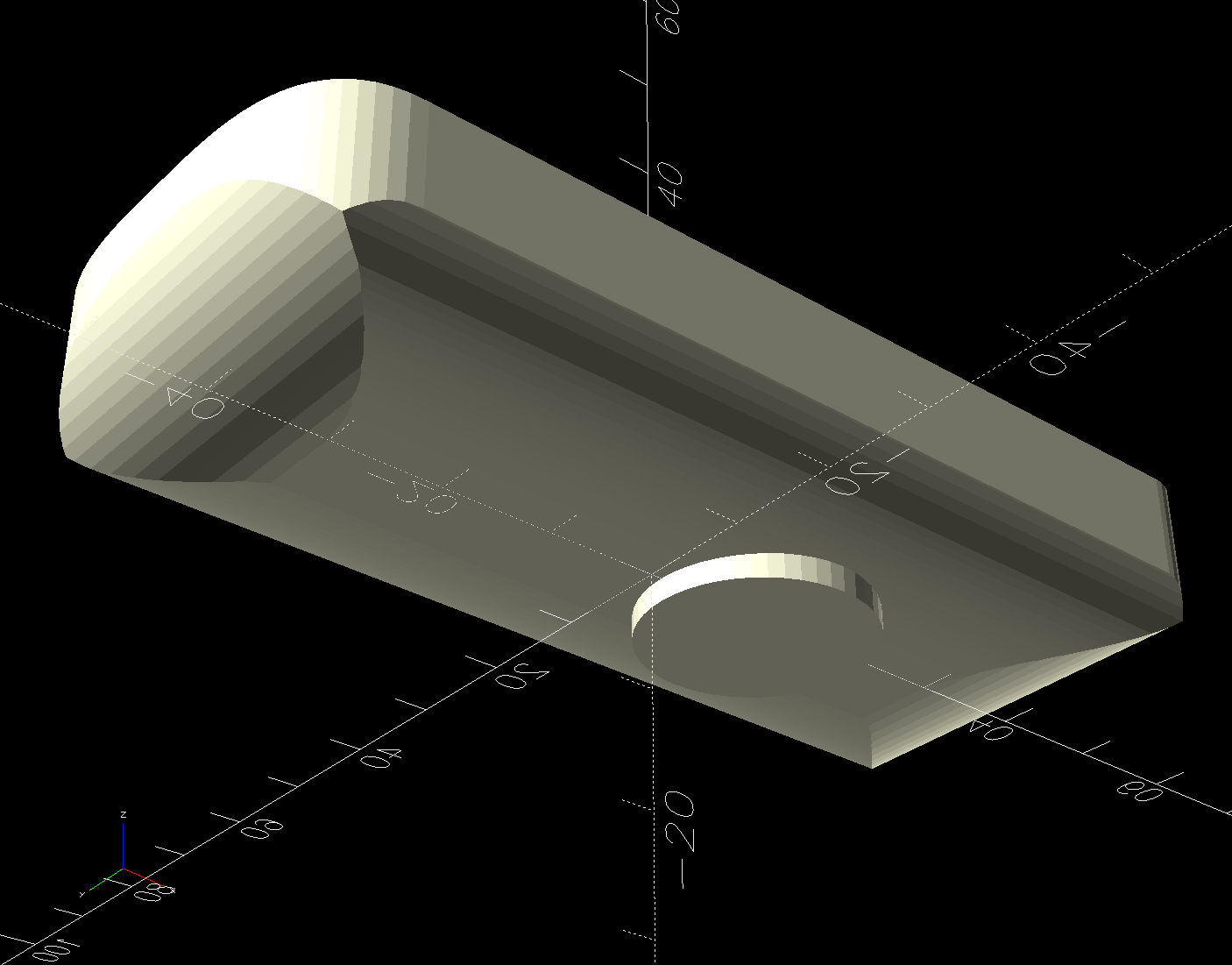
Do the same with a scan of the front face, import the curves into OpenSCAD, extrude them, create a solid model of the remote from their mutual intersection, then add a cylinder to punch the depression for the steel plate:
Floor Lamp Remote Holder – solid model – bottom
The chonky model corners stick out too far compared to the stylin’ curves on the real remote, but I made the holder shorter than the remote specifically to avoid fussing with such details.
Floor Lamp Remote Holder – solid model – Show view
I briefly considered a circumferential clamp around the pipe before coming to my senses and making the pipe diameter 2 mm larger to accommodate a strip of double-sided foam tape.
The magnet gets a ferocious grip on the plate and I defined the result to be All Good™.
The OpenSCAD source code and SVG paths as a GitHub Gist:
This file contains hidden or bidirectional Unicode text that may be interpreted or compiled differently than what appears below. To review, open the file in an editor that reveals hidden Unicode characters.
Learn more about bidirectional Unicode characters
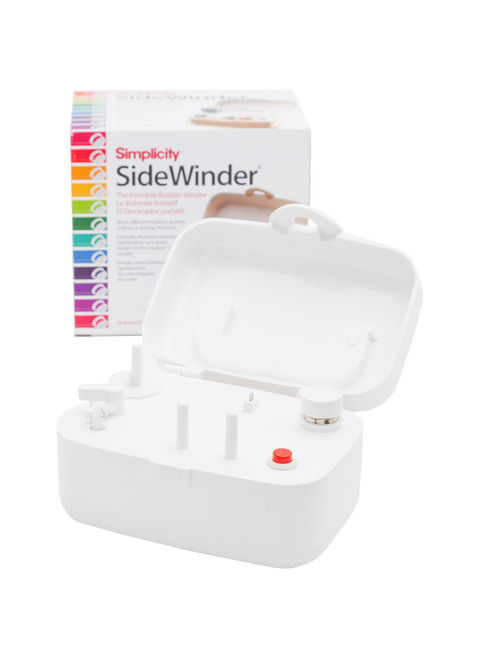
Looks kinda pallid to me, too, although hardcore BarbieCore is also most definitely not our thing.
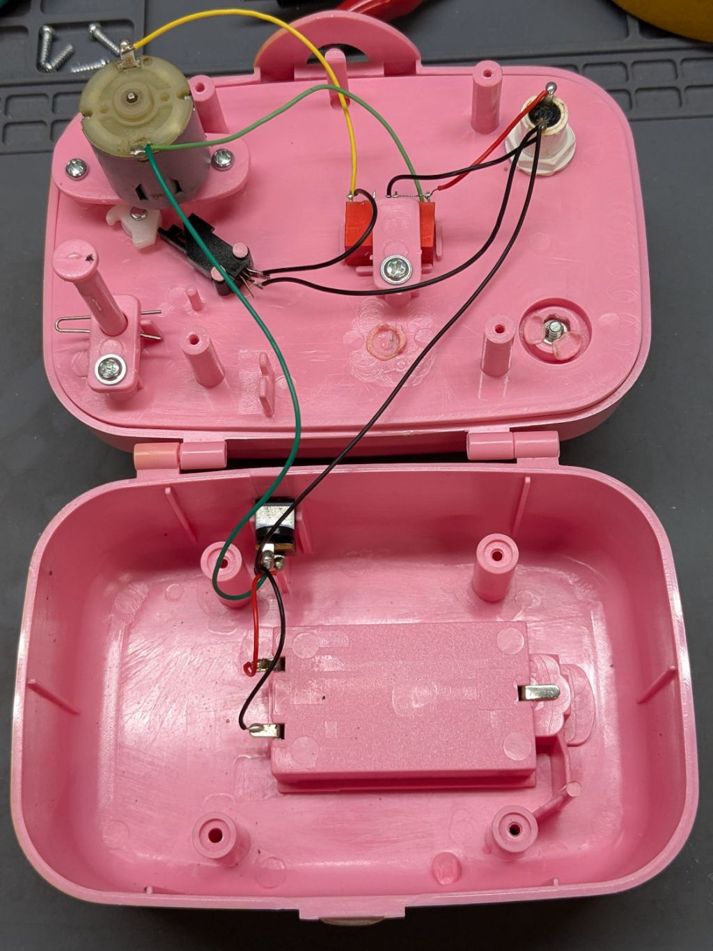
Anyhow, the motor didn’t even twitch when pressing the button, so after I verified the two AA alkaline cells were Just Fine, I laid it on the Electronics Bench and popped the top to see what was the matter:
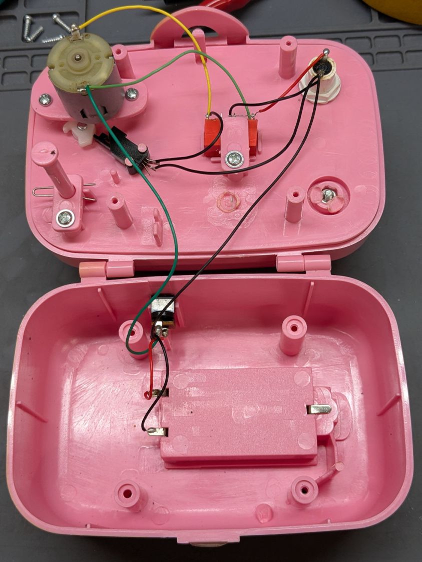
Sidewinder bobbin winder – interior wiring
For the record, the red and black wires at the battery compartment are exactly reversed from what you might expect based on, say, the colors of your multimeter probes. I know better, but it comes as a surprise every time.
The pushbutton switch pulls in the relay (red block in the middle), which latches on until the bobbin fills and the accumulated thread lifts the finger riding on the bobbin to rotate the white cam (under the motor), thus opening the switch (black block), releasing the relay, and shutting off the motor.
Which, of course, worked perfectly after I stuck the alkalines back in place on the bench and poked the button to watch the proceedings.
It’s all back together again and continues to run, so I’ll declare victory until the next time she fills a bobbin and, predictably, it doesn’t start.
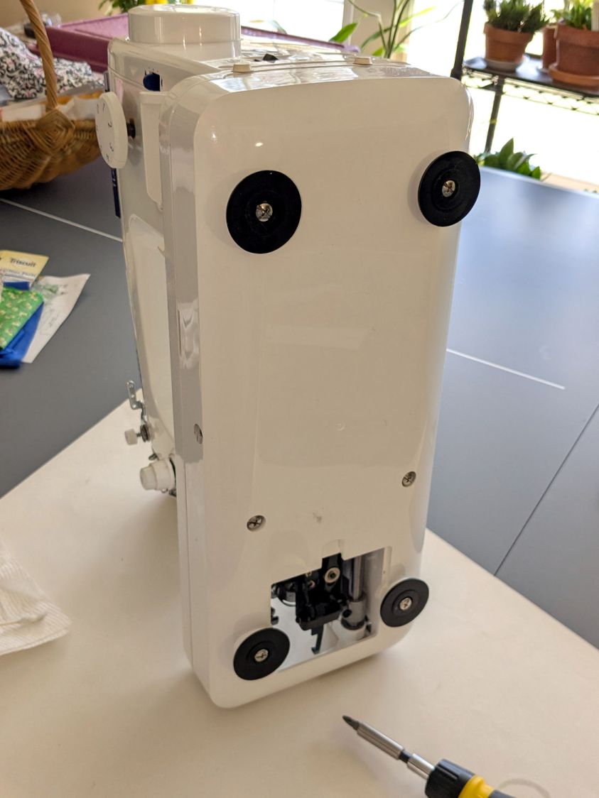
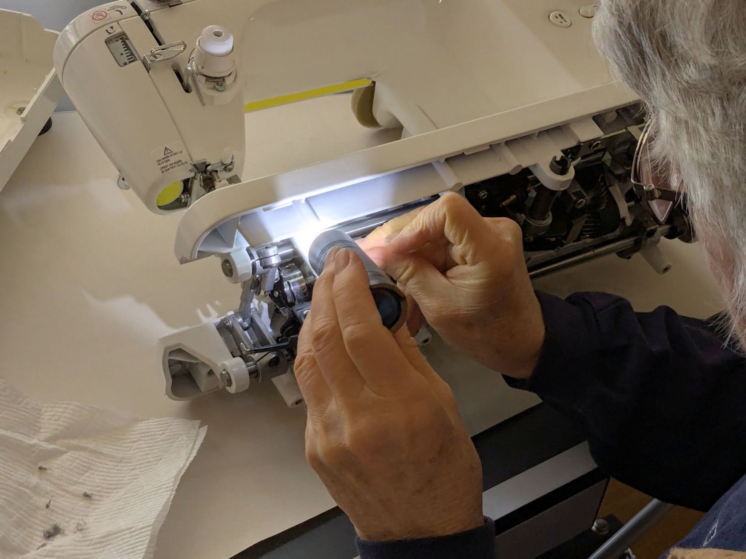
Mary gave her Juki TL-2010Q sewing machine a deep cleaning & oiling, deputizing me to remove & replace the covers.
For the record, standing the machine on its left end is the least-awful way to get the bottom cover off and on:
Juki TL2010Q – bottom cover on end
You must remove all six of those husky screws; the black feet remain firmly stuck in their recesses. It’s not particularly stable in that orientation, so keep a firm hand on the top to prevent an expensive fall.
I laid it down for the rest of the session:
Juki TL2010Q – interior cleaning
She was unenthusiastic about wearing my headband light. Maybe next time.
It reassembled in reverse order and, after a brief tussle with the bobbin winder finger in the upper covers, runs smoothly.
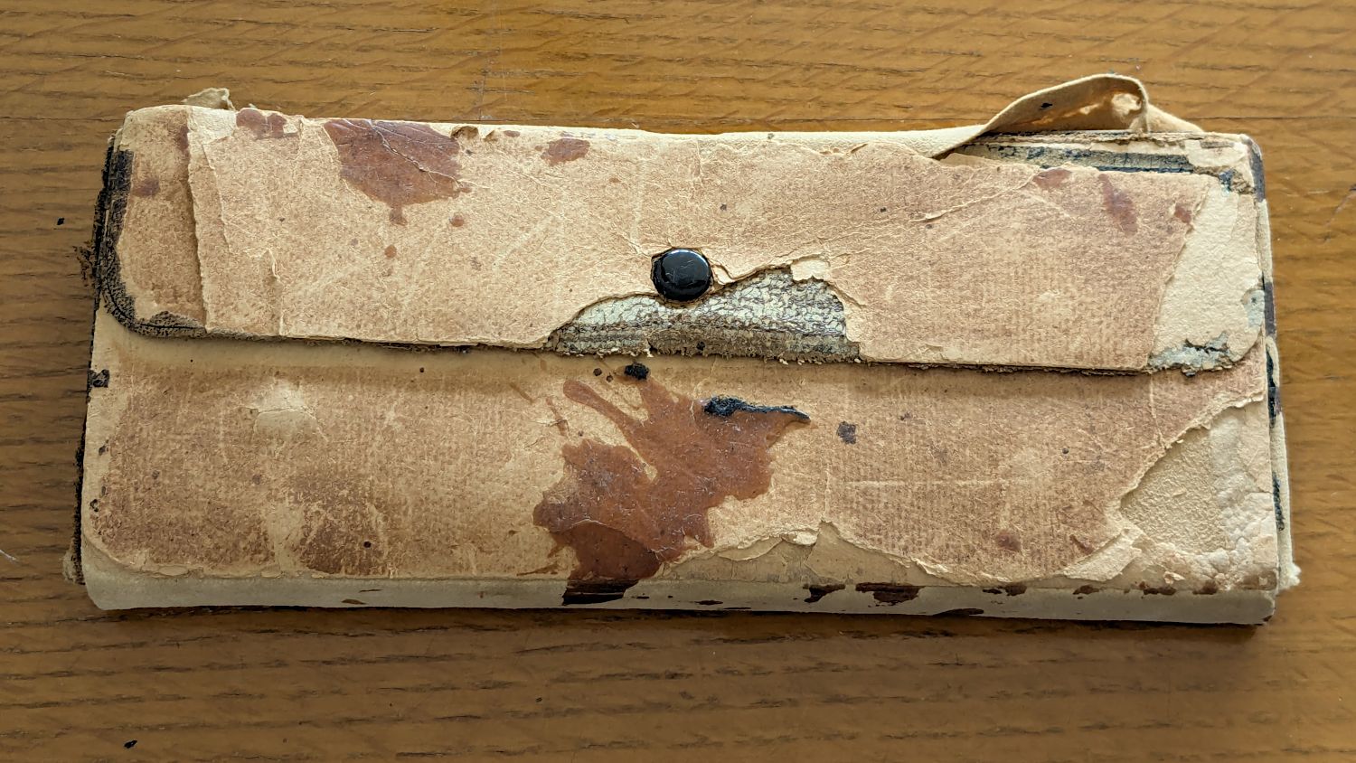
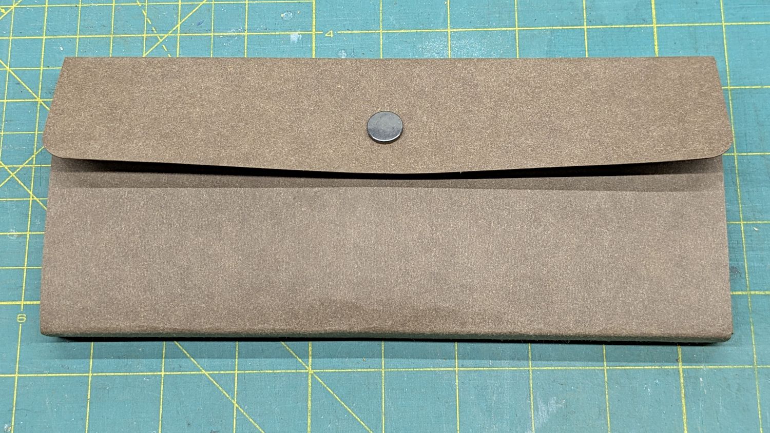
Our Young Engineer recently rebuilt the cover of a “vintage” drawing kit, with fabric pockets for protractors & scales and real leather hinges, thereby raising a long-procrastinated project to the top of my to-do list:
TEC Drawing Set – top old
I know my father used it when he took drafting after high school in 1929. His penmanship and drawing ability were up to par well before that.
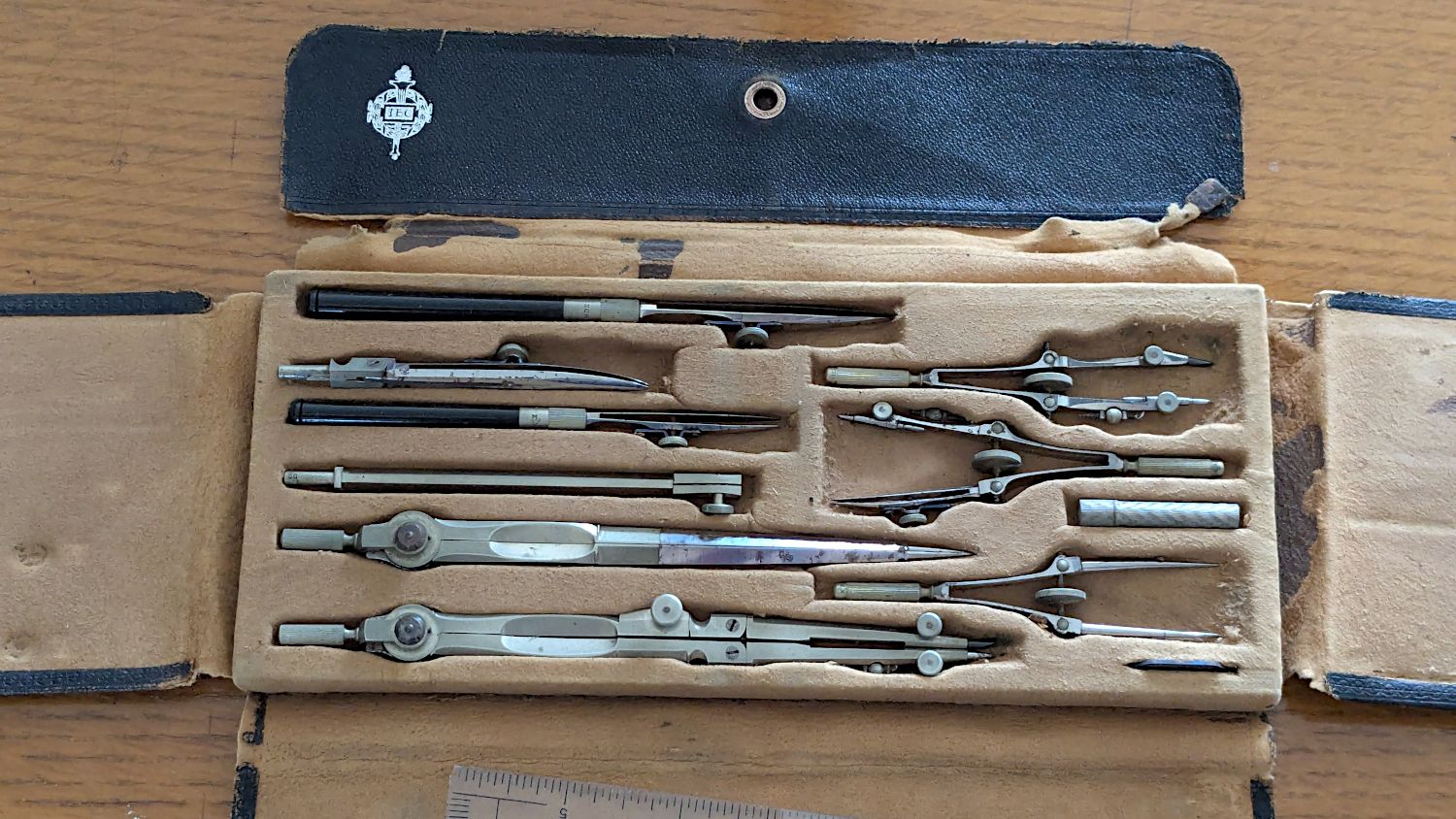
The inside sports a TEC logo:
TEC Drawing Set – open old
Some searching revealed it’s a No. 718 Drafting Set from the Technical Supply Company of Scranton and appeared in their 1913 catalog:
TEC Brand Catalog p68
The printing on the inside of the flap differs, but the logo has TEC in the middle.
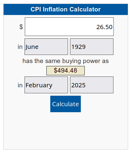
My father did not attend college and, in the teeth of The Great Depression, $26.50 was certainly too spendy for his family:
CPI Calculator – 1929 to 2025
When the catalog was printed in 1913, No. 718 cost the equivalent of $862.82. Nowadays, similar sets once again cost about twenty bucks on eBay, which tells you something about economics.
In retrospect, I should have used two leather snaps, but three would be excessive.
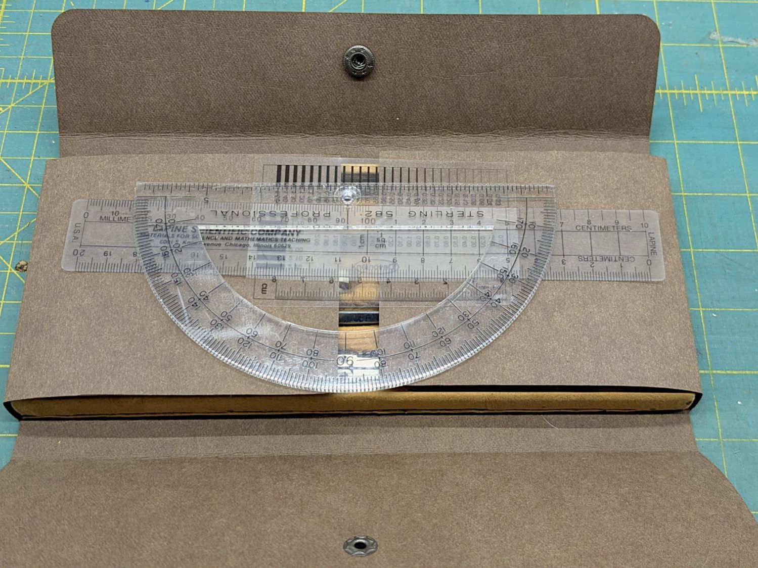
I folded the Kraft-Tex flat across a steel scale to make the first folds around the base, then finger-crimped folds at the top of the base with subsequent crisping around the scale:
TEC Drawing Set – open new
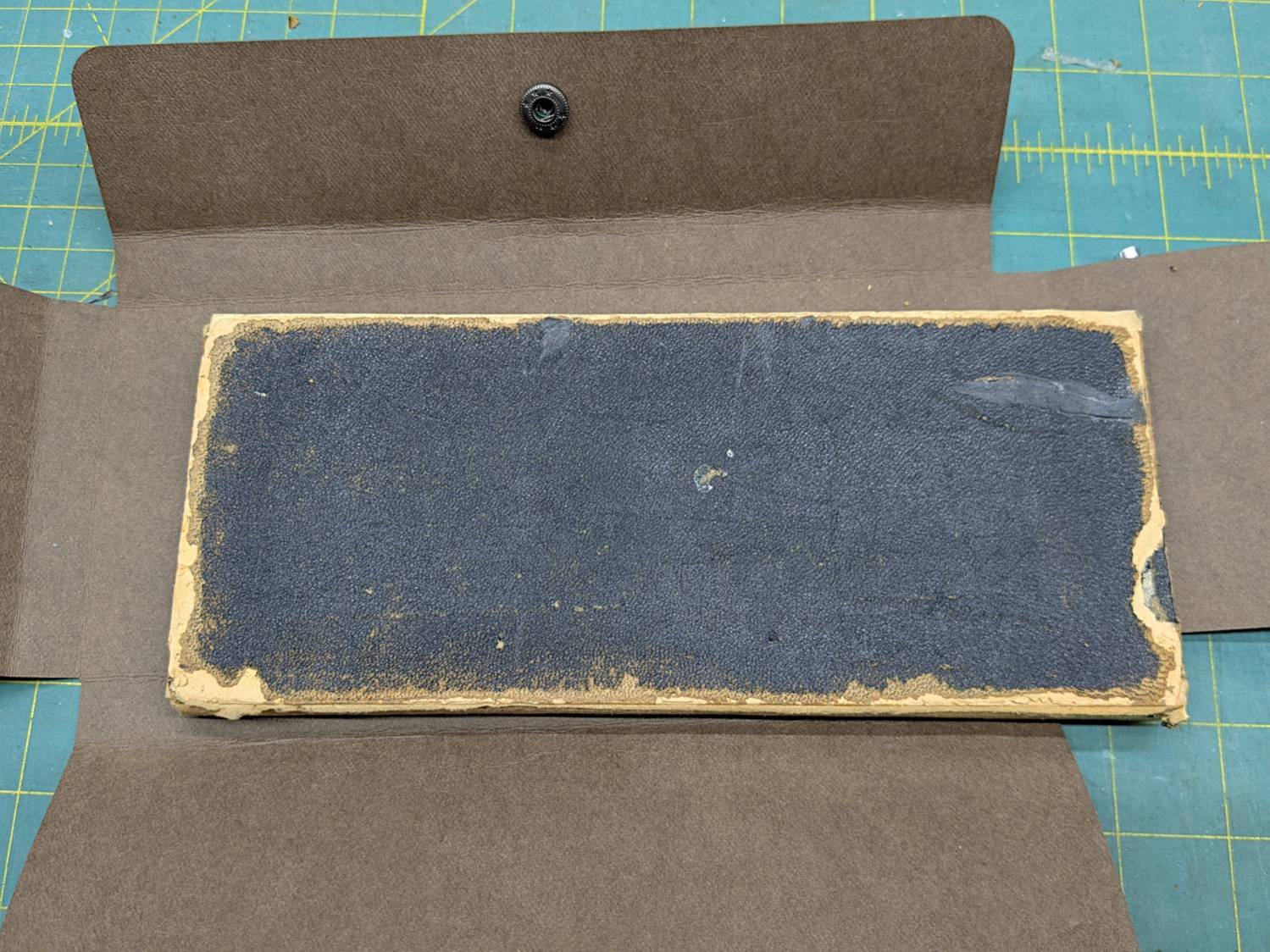
The underside of the original case seemed stable:
TEC Drawing Set – case bottom
This may be sacrilege, but I saw no point in peeling the bottom just to cover it up,so I stuck the Kraft-Tex in place with a rectangle of adhesive sheet.
It doesn’t look the same, but it still gives me a warm feeling.
It still has the tiny wrench needed to adjust all its screws:
TEC Drawing Set – wrench
It’s on 0.1 inch graph paper and is 40 mil = 1 mm thick, should you want to make your own. The blades taper down to essentially a knife edge, which is why it’s made from hard blue steel.
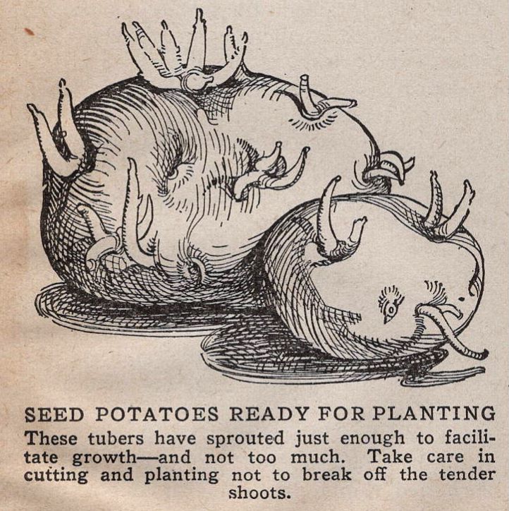
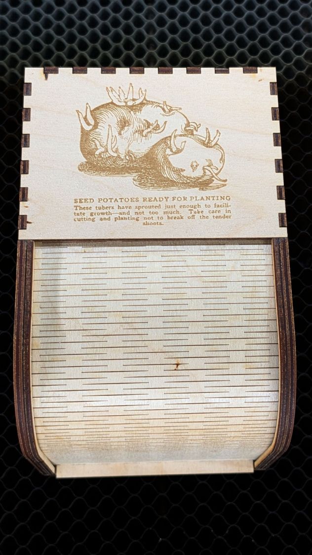
I remember being fascinated by that little pig when I was a pup.
Putting some scraps to good use, I stuck a cushion in the anvil for the next time I punch down a leather snap:


