When our stick blender (Cusinart CSB-77, with an instruction manual dated 2011) failed, I dropped fifteen bucks on the shortest one we could find, which turned out to be inconveniently long for the shorter member of the user community. The old one recently emerged from the depths of the bench for triage; the failure was in the coupler between the motor and the blade shaft, but required complete disassembly before trying to repair it.
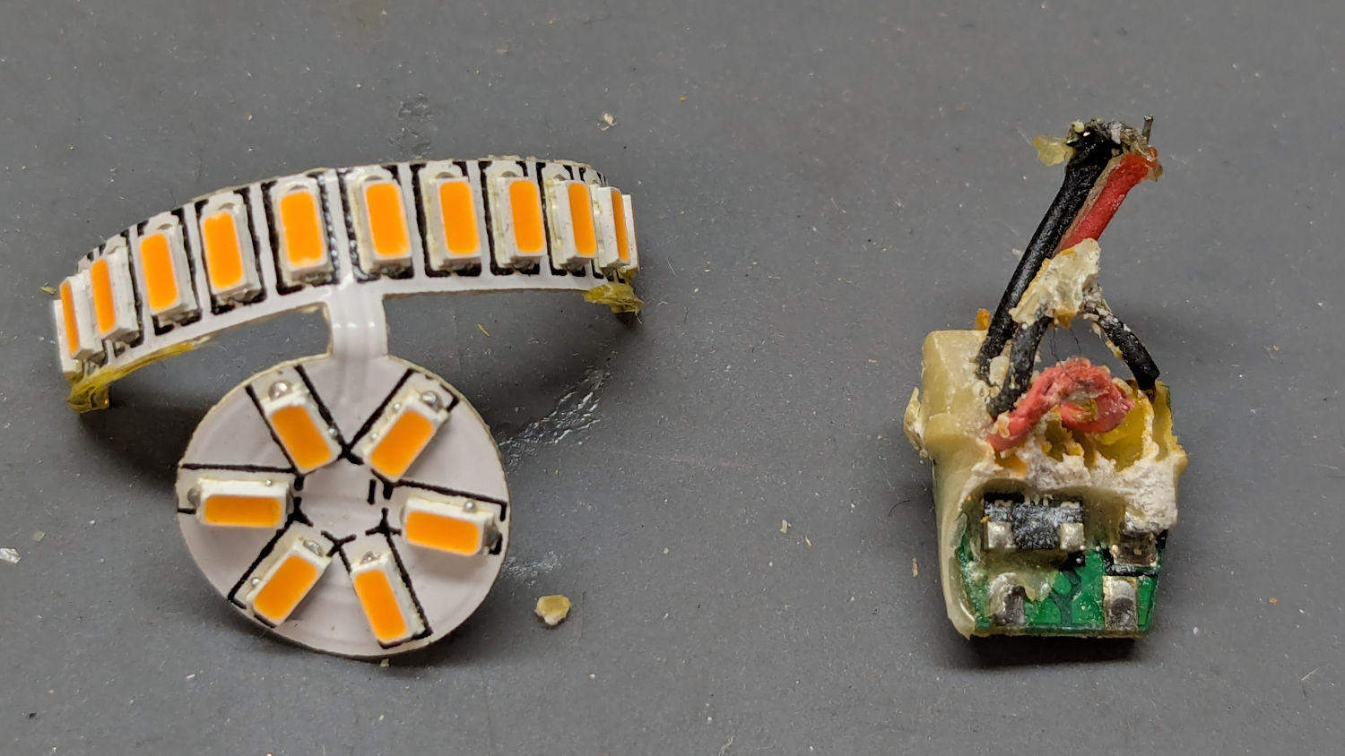
Pry out two obvious plastic plugs, remove two screws holding the top of the handle together, pull the handle apart, and reveal a PCB with a discrete diode bridge and an open-frame switch:

Fortunately, the wire colors matched my preconception. Unsolder the wires to get that side of the handle off.
Un-bend the tab holding the metal shell to the plastic frame and pull it off, whereupon the frame halves unsnap to release the motor:

The white nylon (?) coupler on the motor shaft pries off the splined motor shaft:
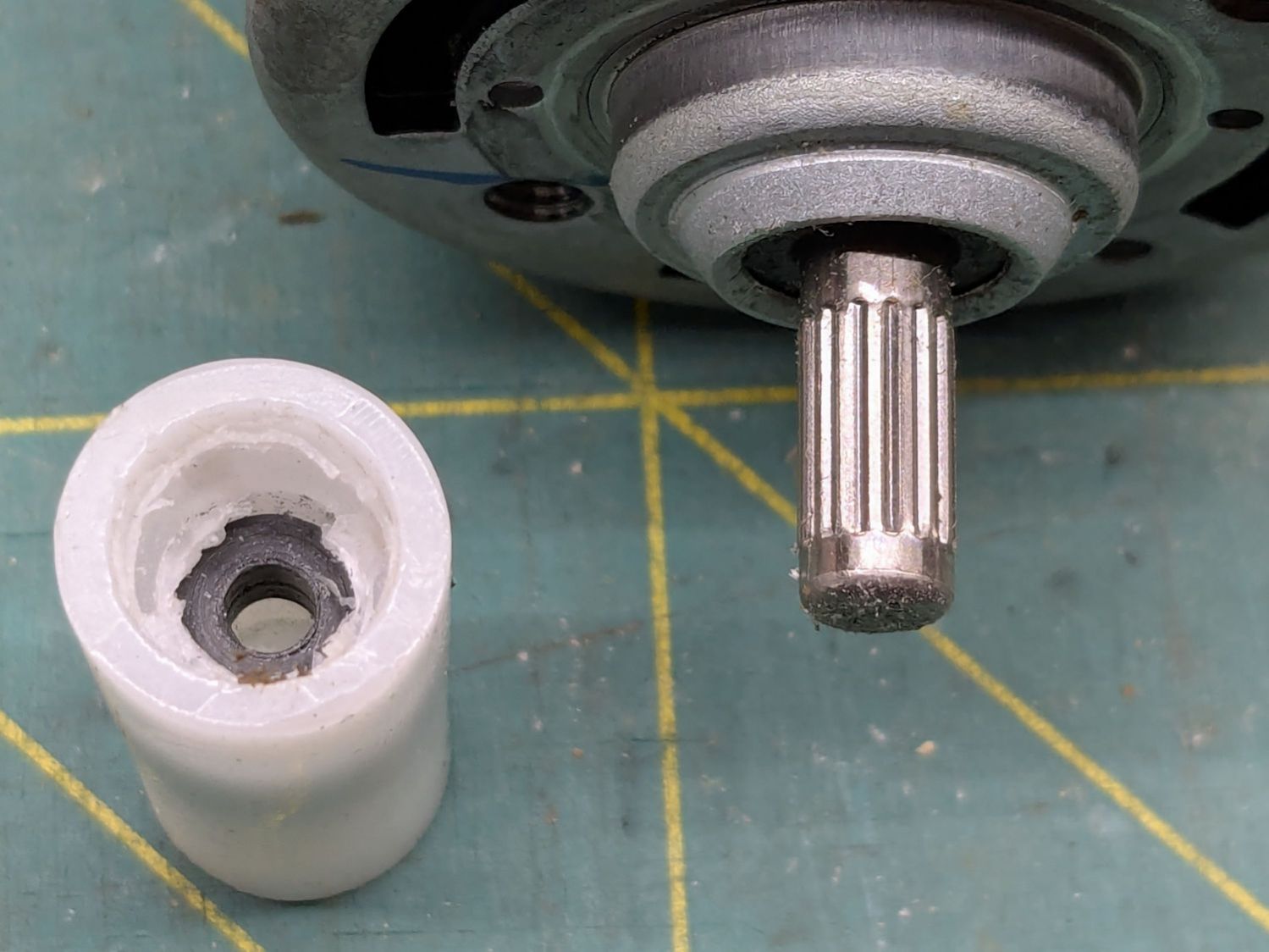
That black ring inside the coupler should be on the blade shaft:

It apparently got jammed in the coupler when the shaft’s drive dogs / splines (barely visible down inside) ripped up the coupler. I don’t know if that was a sudden failure or the end result of gradually accumulating damage, but the inside of the coupler was badly chewed up.
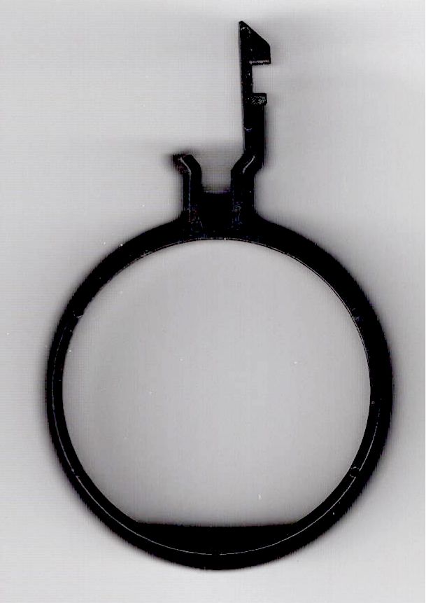
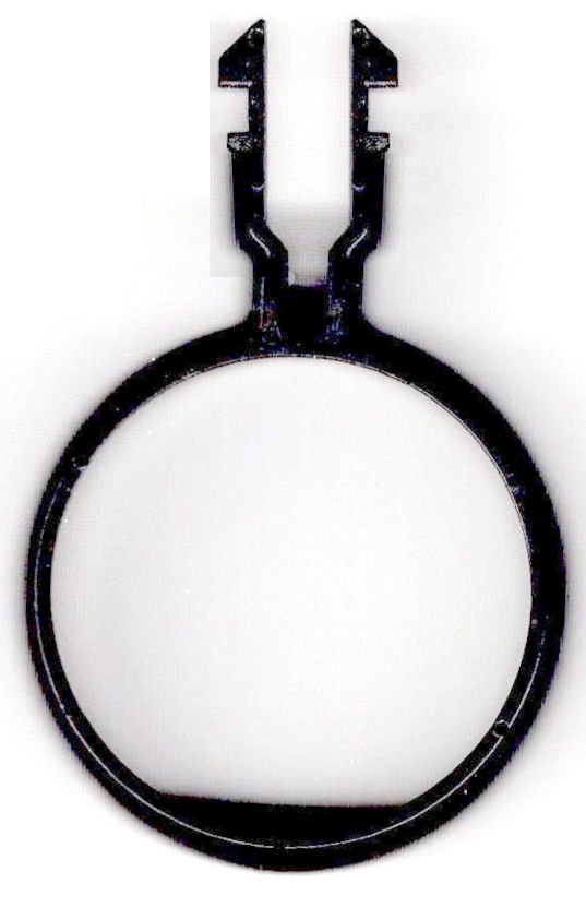
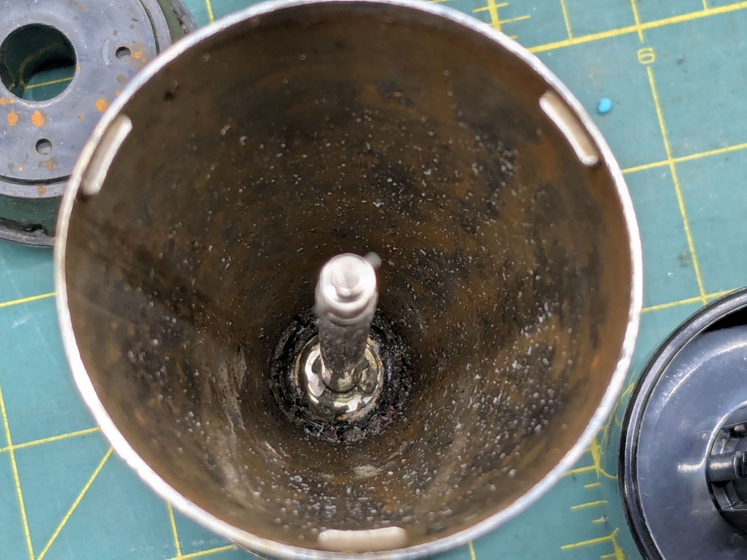
Dismantling the blade unit requires prying three plastic clips back, one at a time, while pushing upward on the intricate black plastic fitting around the shaft:

That let me ease a drop of oil down the shaft to what looks and feels like a plastic sleeve bearing near the blade end of the housing; oil should not be needed on a plastic bearing, but it definitely improved the bearing’s attitude. The snap ring securing the shaft is far enough away to prevent me from even trying to remove it, because I know there is no way I can reinstall it:
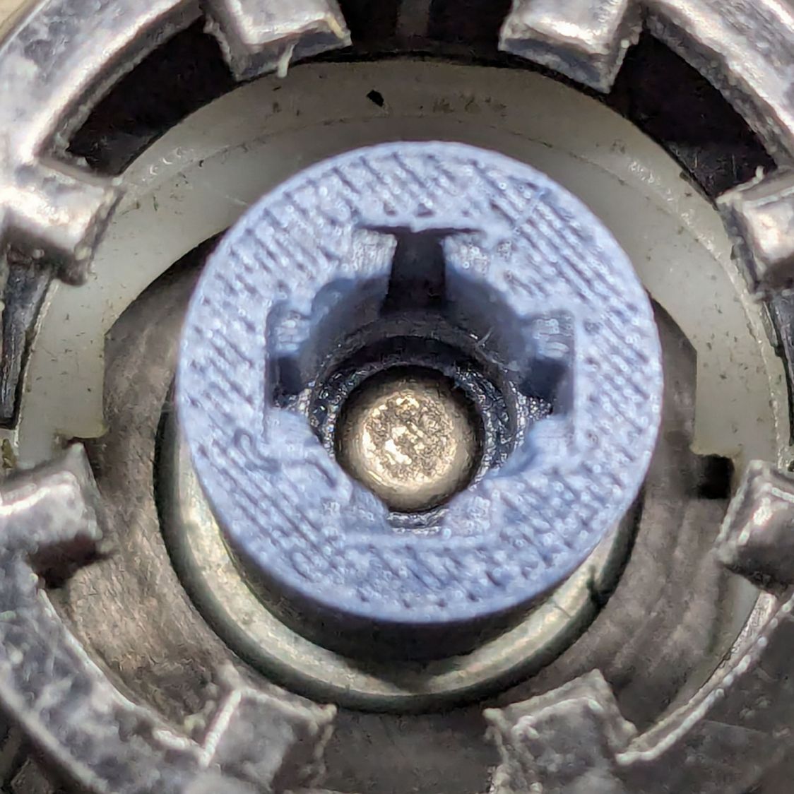
Some Xacto knife action removed the shredded plastic to reveal the remains of four slots for the blade shaft’s two drive dogs / splines:

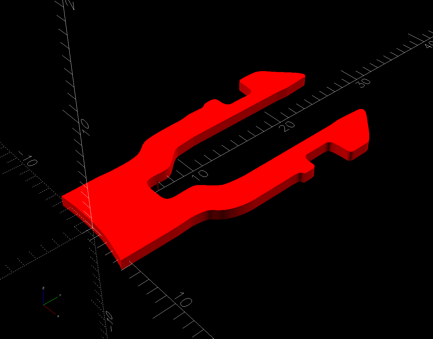
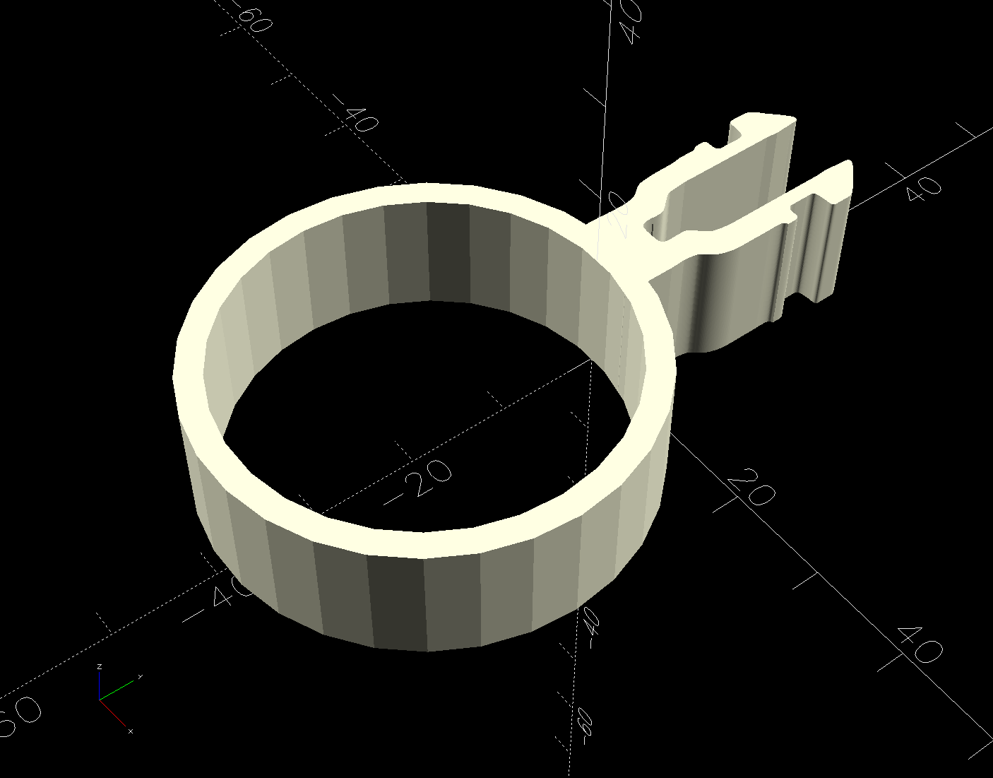
Measuring All. The. Things. produced a reasonable solid model of the slots:

Removing those from a model of the coupler defined the shape:
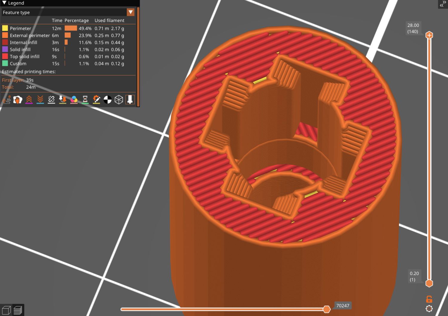
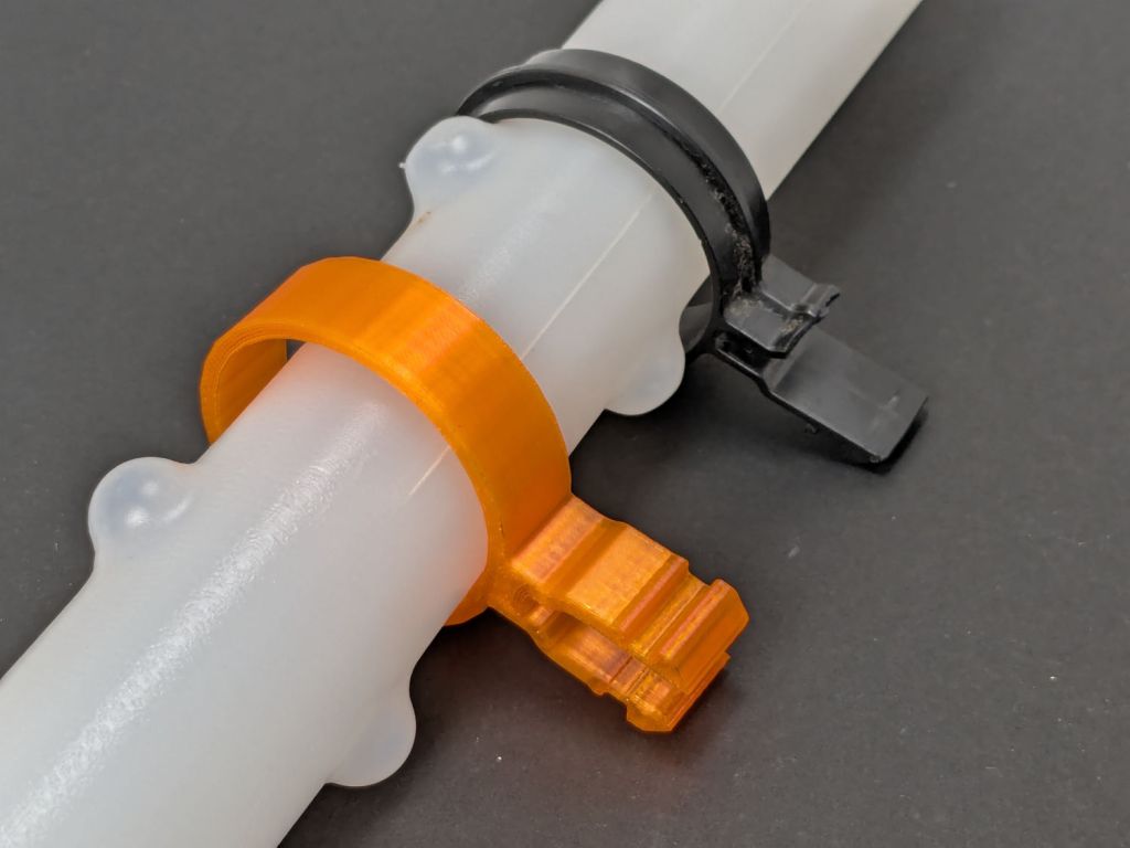
As usual, having one in hand let me check the fit and, after a few tweaks, the next one was Just Right™.
The other end of the coupler is a simple cylinder sized for a firm press fit on the motor shaft splines:
My coupler is chunkier than the OEM coupler, because there was enough room in there and PETG-CF, being weaker than nylon, needs all the help it can get:

It’s one of the few things I’ve printed with 100% infill. If when that plastic fails, I’ll try something else.
Put the little rubber ring on the blade shaft and reassemble everything in reverse order:

The blender works as well as it ever did, while the halves couple and uncouple the way they should, so we’ll declare victory and keep the new blender as a backup.
The OpenSCAD source code as a GitHub Gist:
| // Stick Blender drive coupler | |
| // Ed Nisley – KE4ZNU | |
| // 2025-05-16 | |
| include <BOSL2/std.scad> | |
| Layout = "Show"; // [Show,Build,Splines] | |
| /* [Hidden] */ | |
| HoleWindage = 0.2; | |
| Protrusion = 0.1; | |
| NumSides = 3*3*4; | |
| ID = 0; | |
| OD = 1; | |
| LENGTH = 2; | |
| ShellOA = [5.0,14.0,28.0]; // ID=motor shaft | |
| MixerSocket = [6.6,0,17.2]; // passes rubber retainer | |
| Retainer = [3.0,6.5,5.5]; // ID=mixer shaft,OD=rubber ring | |
| RetainerRebate = [Retainer[ID],3.9,1.5]; // … fits under shaft lip | |
| DriveSocket = [6.7,8.8,12.0]; // OD=notch OD | |
| DriveNotch = [(DriveSocket[OD] – DriveSocket[ID])/2,1.5,DriveSocket[LENGTH]]; // … drive notch shape on +X | |
| DriveChamfer = -DriveNotch.y; | |
| $fn = NumSides; | |
| //———- | |
| // Define Shapes | |
| module Splines() { | |
| render() | |
| for (a = [0:90:270]) | |
| zrot(a) | |
| right(DriveSocket[ID]/2 – Protrusion) | |
| cuboid(DriveNotch + [Protrusion,0,0],chamfer=DriveChamfer,edges=[TOP+FWD,TOP+BACK],anchor=LEFT+BOTTOM); | |
| } | |
| module Coupler() { | |
| difference() { | |
| tube(ShellOA[LENGTH],id=ShellOA[ID],od=ShellOA[OD],anchor=BOTTOM); | |
| up(ShellOA[LENGTH] – MixerSocket[LENGTH]) | |
| cyl(Retainer[LENGTH],d=Retainer[OD],anchor=BOTTOM); | |
| up(ShellOA[LENGTH] + Protrusion) | |
| cyl(DriveSocket[LENGTH] + Protrusion,d=DriveSocket[ID],anchor=TOP); | |
| up(ShellOA[LENGTH] – DriveNotch[LENGTH] + Protrusion) | |
| Splines(); | |
| } | |
| } | |
| //———- | |
| // Build things | |
| if (Layout == "Splines") | |
| Splines(); | |
| if (Layout == "Show") | |
| Coupler(); | |
| if (Layout == "Build") | |
| Coupler(); |