Ed Nisley's Blog: Shop notes, electronics, firmware, machinery, 3D printing, laser cuttery, and curiosities. Contents: 100% human thinking, 0% AI slop.
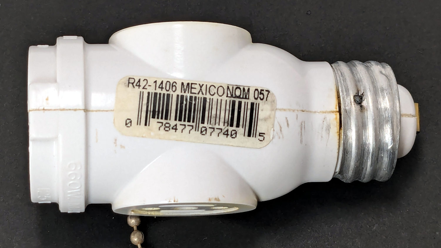
The basement came with several LED bulbs screwed into old-school ceramic sockets with pull-chain switches. This adapter had an LED bulb in its socket and another LED fixture plugged into an outlet:
Lamp socket adapter – failed weld
The fixture began flickering some days ago, which I attributed to a problem with its power supply. When both the bulb and the fixture went dark, I had enough of a clue to locate the real cause.
The scorched plastic near the discolored weld nugget on the threaded shell suggests something ran overly hot in there for a while.
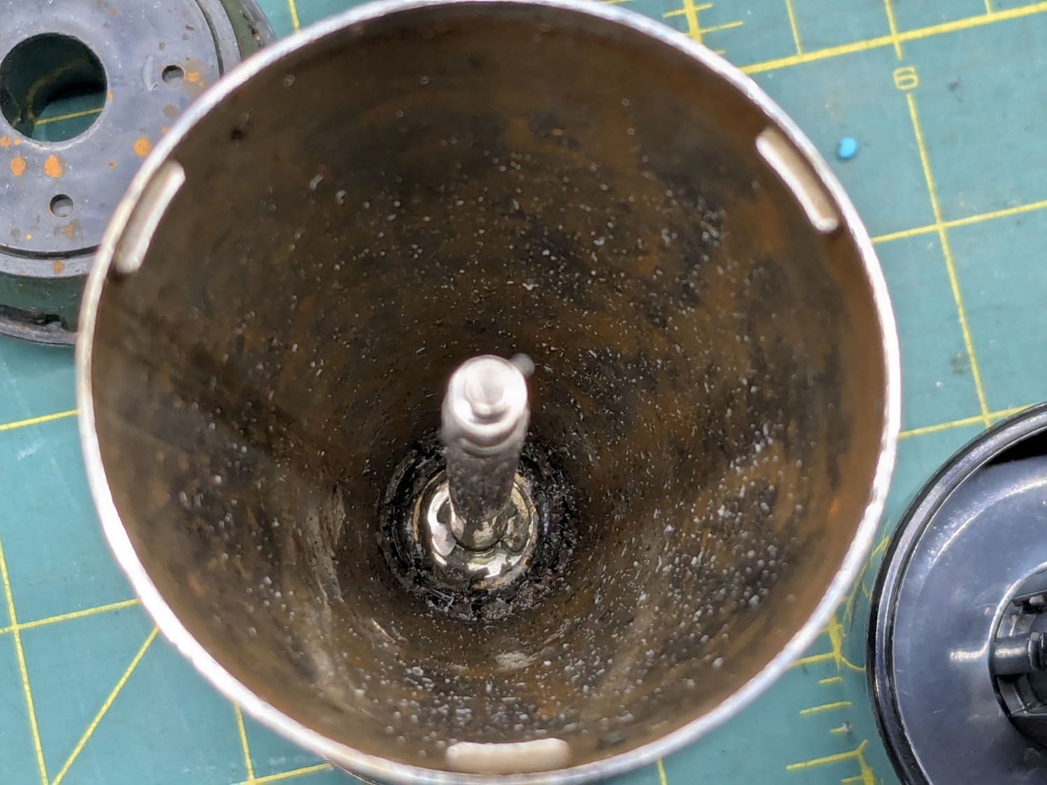
Peeling the aluminum shell off reveals the problem:
Lamp socket adapter – detail
Looks to me like the weld started out weak and gradually fell apart as the socket heated / cooled in use, with increasing resistance producing more heat every time.
The LED lamp + fixture added up to 100 W, so about 1 A is all it takes.
When our stick blender (Cusinart CSB-77, with an instruction manual dated 2011) failed, I dropped fifteen bucks on the shortest one we could find, which turned out to be inconveniently long for the shorter member of the user community. The old one recently emerged from the depths of the bench for triage; the failure was in the coupler between the motor and the blade shaft, but required complete disassembly before trying to repair it.
Pry out two obvious plastic plugs, remove two screws holding the top of the handle together, pull the handle apart, and reveal a PCB with a discrete diode bridge and an open-frame switch:
Stick blender coupler – PCB
Fortunately, the wire colors matched my preconception. Unsolder the wires to get that side of the handle off.
Un-bend the tab holding the metal shell to the plastic frame and pull it off, whereupon the frame halves unsnap to release the motor:
Stick blender coupler – shell removed
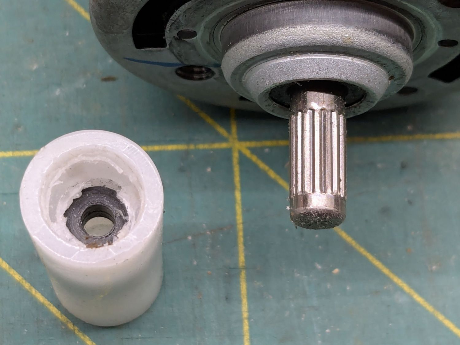
The white nylon (?) coupler on the motor shaft pries off the splined motor shaft:
Stick blender coupler – motor shaft splines
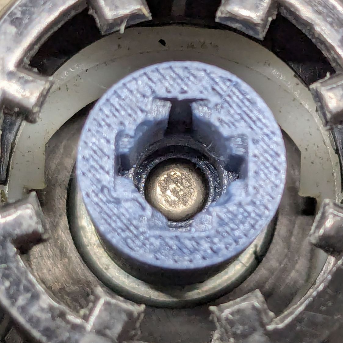
That black ring inside the coupler should be on the blade shaft:
Stick blender coupler – blade shaft
It apparently got jammed in the coupler when the shaft’s drive dogs / splines (barely visible down inside) ripped up the coupler. I don’t know if that was a sudden failure or the end result of gradually accumulating damage, but the inside of the coupler was badly chewed up.
Dismantling the blade unit requires prying three plastic clips back, one at a time, while pushing upward on the intricate black plastic fitting around the shaft:
Stick blender coupler – blade housing clips
That let me ease a drop of oil down the shaft to what looks and feels like a plastic sleeve bearing near the blade end of the housing; oil should not be needed on a plastic bearing, but it definitely improved the bearing’s attitude. The snap ring securing the shaft is far enough away to prevent me from even trying to remove it, because I know there is no way I can reinstall it:
Stick blender coupler – blade shaft snap ring
Some Xacto knife action removed the shredded plastic to reveal the remains of four slots for the blade shaft’s two drive dogs / splines:
Stick blender coupler – OEM coupler end view
Measuring All. The. Things. produced a reasonable solid model of the slots:
Stick Blender drive coupler – splines – solid model
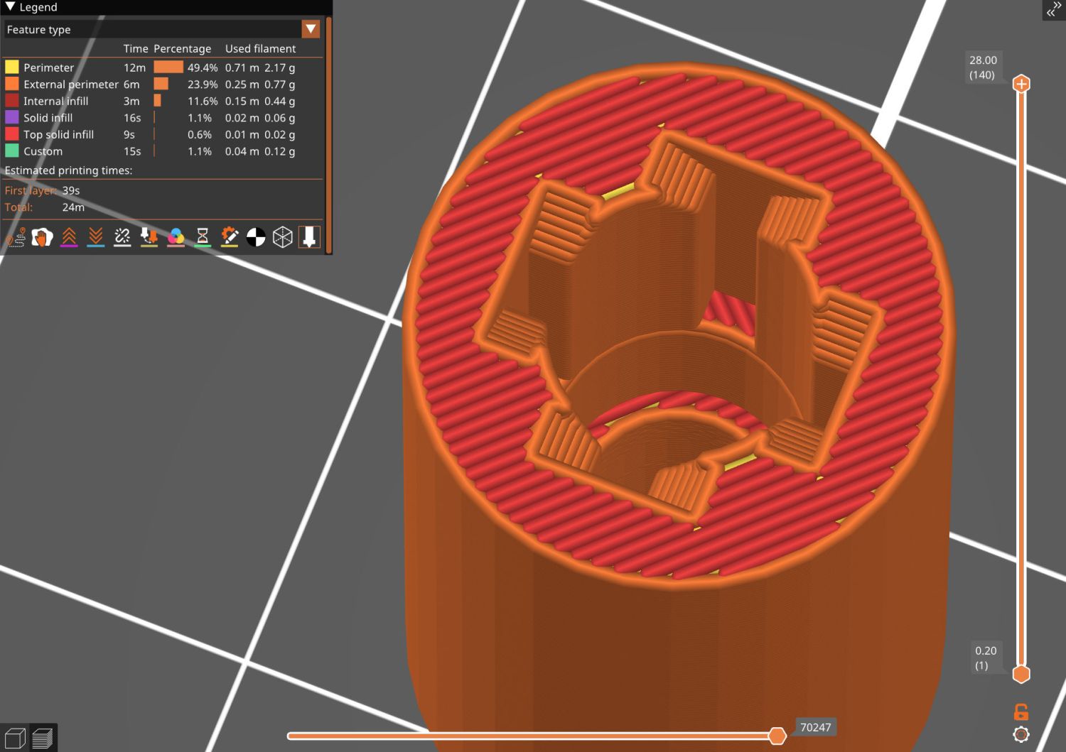
Removing those from a model of the coupler defined the shape:
Stick Blender drive coupler – PrusaSlicer
As usual, having one in hand let me check the fit and, after a few tweaks, the next one was Just Right™.
The other end of the coupler is a simple cylinder sized for a firm press fit on the motor shaft splines:
Stick blender coupler – new coupler detail
My coupler is chunkier than the OEM coupler, because there was enough room in there and PETG-CF, being weaker than nylon, needs all the help it can get:
Stick blender coupler – new coupler installed
It’s one of the few things I’ve printed with 100% infill. If when that plastic fails, I’ll try something else.
Put the little rubber ring on the blade shaft and reassemble everything in reverse order:
Stick blender coupler – mating ends
The blender works as well as it ever did, while the halves couple and uncouple the way they should, so we’ll declare victory and keep the new blender as a backup.
This file contains hidden or bidirectional Unicode text that may be interpreted or compiled differently than what appears below. To review, open the file in an editor that reveals hidden Unicode characters.
Learn more about bidirectional Unicode characters
The venerable (circa 1993) Whirlpool clothes dryer (LER443AQ0) that Came With The House™ failed in action: the drum occasionally stopped turning (and, fortunately, heating) while the control timer continued ticking along. The symptoms suggested one of the many thermal switches / thermostats / fuses was bad, but because the problem was intermittent, the only practical alternative was replacing all the things.
Which, it turns out, costs about ten bucks from the usual source. I remain unconvinced paying an order of magnitude more for what look to be identical parts will, in fact, bring either different parts or higher quality.
The wiring diagram, which I consulted only after the fact, shows it was most likely the “Not Resettable” Thermal Fuse in series with the drum motor, because the other contestants are in series with the heater and the Operating Thermostat would trip when the blower stopped blowing:
Whirlpool dryer – wiring diagram – detail
The fact that the Thermal Fuse should not “reset” after it trips seems worrisome, but failures are like that.
All those parts are accessible only through the rear cover, but you should definitely vacuum out as much fuzz as possible before popping the cover (with vacuum in hand):
Whirlpool dryer – heater duct top
Of course, all the old parts show fine continuity, because intermittent:
Whirlpool dryer – thermal switches
With the new parts in place, the dryer has chugged through half a dozen loads without incident: so all’s well that ends well.
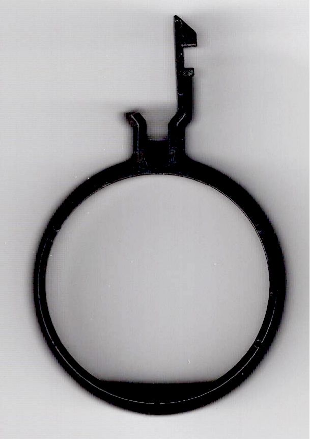
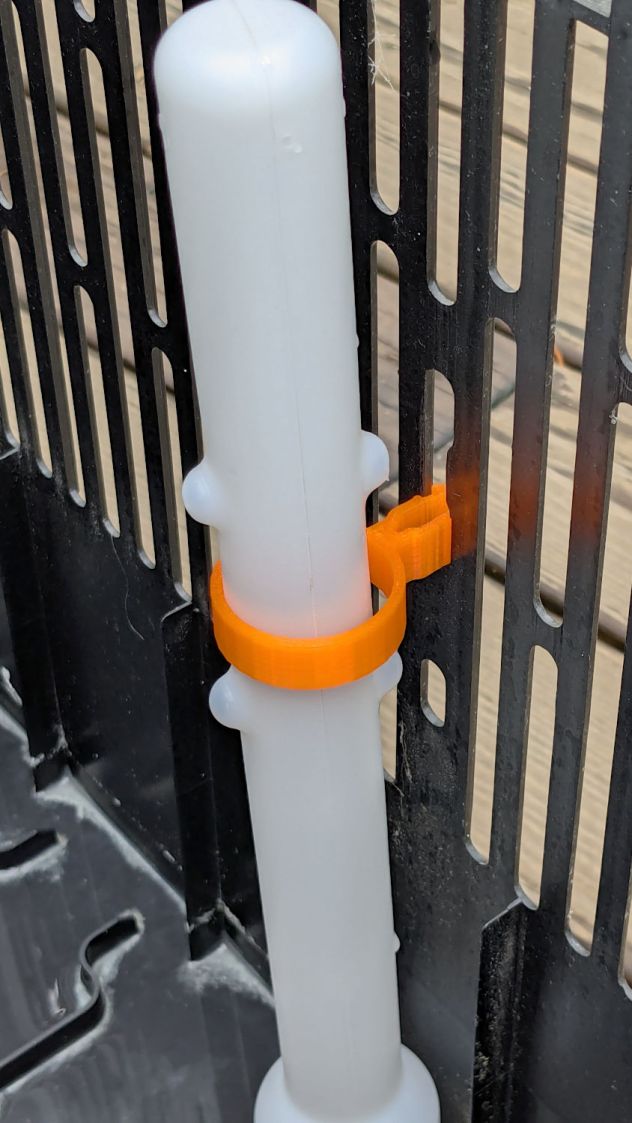
This being the end of the humidifcation season, I tried to set the longsuffering Sears Humidifier’s water level float to dry the thing out. After a few days, it became obvious that wasn’t working and I eventually found the clip intended to hold the float at the top of its travel had broken:
Humidifier float clips – on float
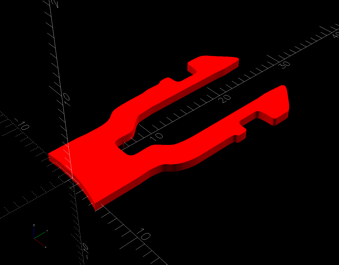
Building the retina-burn orange replacement started with a scan of the original:
Humidifier float clip
The black segment at the bottom is a shadow due to the scanner’s light bar being offset from the imaging sensor.
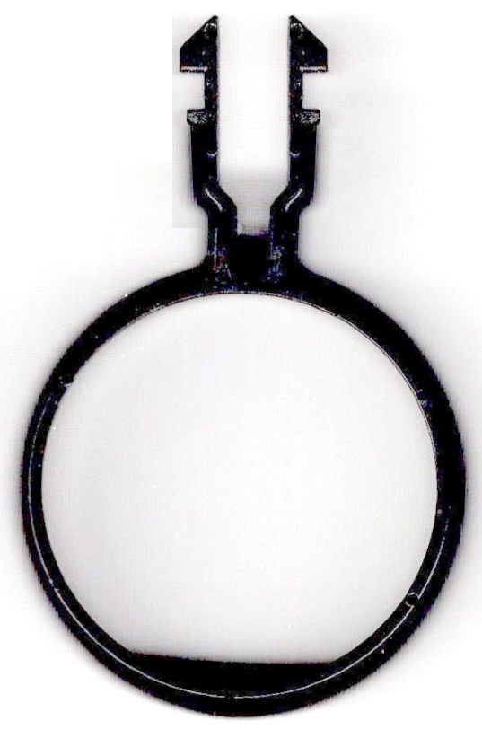
Using GIMP, duplicate the remaining part of the latch, flip it left-to-right, then align it at the proper position:
Humidifier float clip – repaired
The latch is the only tricky part and the ID of the ring is easy to locate, so (still in GIMP):
Trace the edge of the whole shape
Using Quick Mask mode, remove all but the latch
Convert the selection to a path
Export it as an SVG file
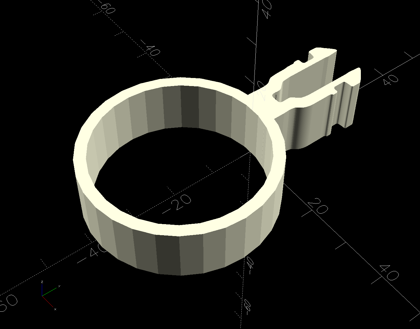
Then import it into OpenSCAD and eyeballometrically translate the shape to put the ring ID at the origin:
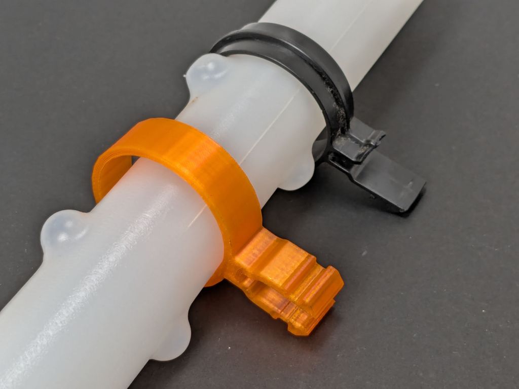
There being no obvious affordance to get the ring over the two bumps in the float, I applied Channellock pliers to the float while easing the ring into place.
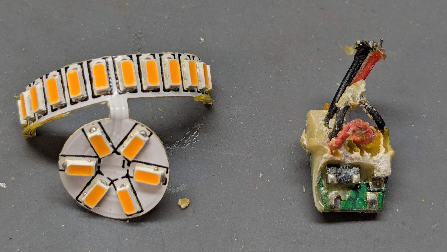
Six years ago I replaced the W5W incandescent front side marker bulbs in our 2015 Subaru Forester with amber LED bulbs:
Side Marker bulbs – failed adhesive
The adhesive holding the LED PCB to the aluminum “heatsink” has fossilized and the strip on the right is peeling off (with the left one not far behind), which likely accounted for its loss of light output and flickering.
Tearing it apart reveals the LED layout and what looks like a bridge rectifier or a big resistor (to fool the CAN bus?) on a tiny PCB jammed inside the shell:
Side Marker bulbs – rectifier
The other side of the PCB could be a buck converter:
Side Marker bulbs – buck converter
In round numbers, we’ve driven 18000 miles at an average of maybe 40 mph over those years; call it 450 hours. However, the side marker lights aren’t on unless the headlights are on; we do very little night driving, which means those LED bulbs are the usual crap.
A postcard arrived last week telling me to call a special number for special deals on Medicare Advantage plans. Being that type of guy, I managed to read the microscopic Fine Print and found this amusing blooper amid the disclaimers weasel wording:
Medicare Advantage mail spam
Inserting insurance carrier names should have happened before printing the card, so [CarrierA] and [CarrierB] are either placeholders or mail-merge variables.
Also, you’re seeing the contrast-blown and magnified version of the postcard. The original Fine Print had faint orange ink on light green cardstock: colors having different hues with the same saturation and value to minimize legibility. In general, folks eligible for Medicare Advantage plans have trouble reading Fine Print, so the choice was not accidental.
This housing development was the second in Poughkeepsie to have underground utilities and, to put it mildly, a lot has rotted out over the last 70 years.
Over the weekend, one phase of the AC power flickered and eventually failed completely, with the other phase supplying a steady 120 VAC. Central Hudson (Gas & Electric) crews located long-lost buried boxes in places not matching their maps:
Power Outage – flooded box
Then they pumped / bailed enough water to repair / lengthen the wires:
Power Outage – corroded wiring
I’ve never before seen anybody work on live wires underwater.
They installed above-ground boxes to simplify The Next Time.
Some improvisation was required:
Power Outage – improvised cocoa stirring
Gotta say, cold Fireball Cocoa tastes different than hot Fireball Cocoa.