Ed Nisley's Blog: Shop notes, electronics, firmware, machinery, 3D printing, laser cuttery, and curiosities. Contents: 100% human thinking, 0% AI slop.
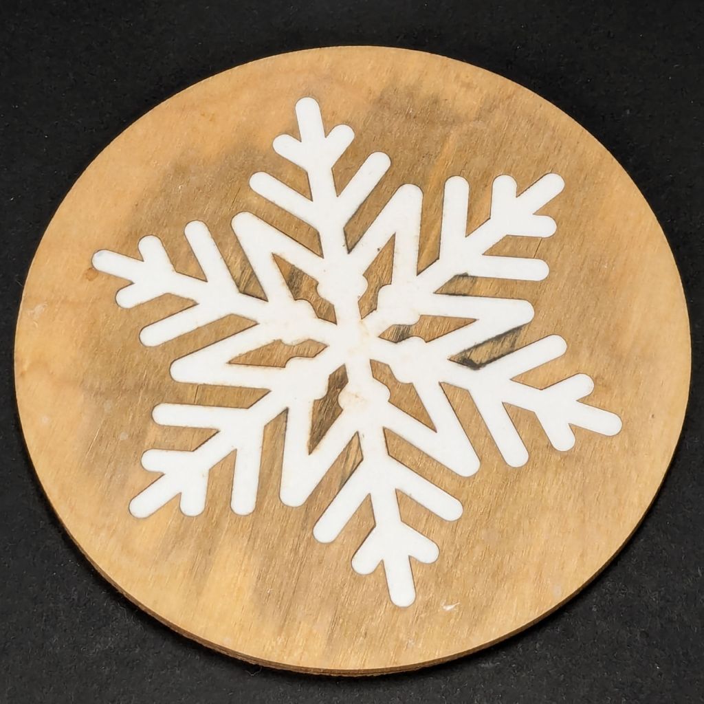
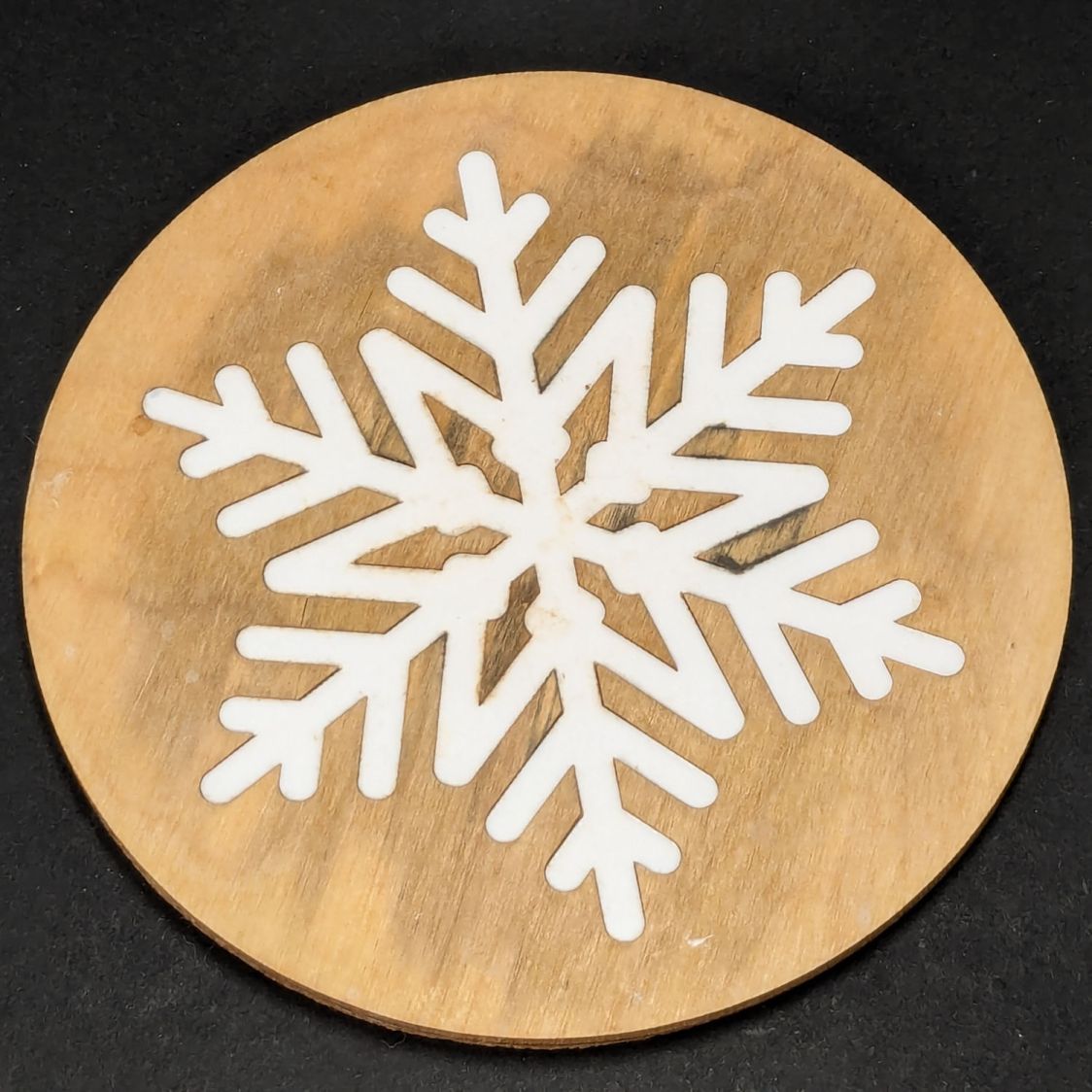
After more-or-less constant use under a cup in the bathroom, a Snowflake Coaster has reached the end of its life:
Snowflake coaster – 1 yr use
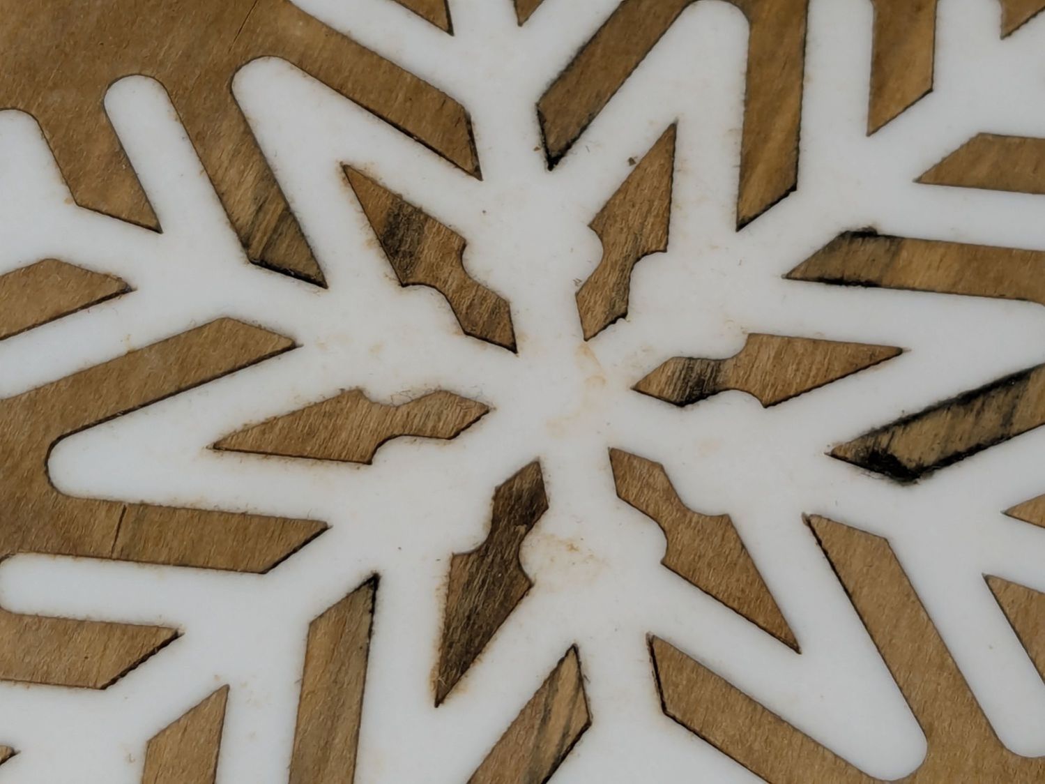
The acrylic flake is fine, but the wood has mildewed:
Snowflake coaster – 1 yr use – detail
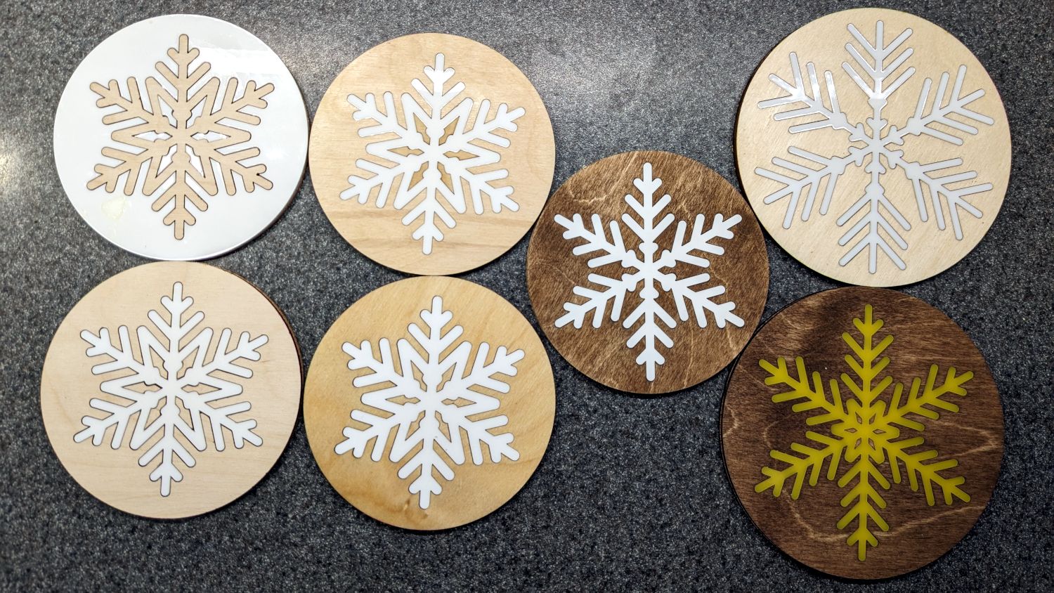
It’s second from the left in the bottom row:
Snowflake Coaster – assortment
All except the pair in the left column had a coat or two of rattlecan clear, which suggests wood-ish coasters need something much more durable, along the lines of clearcoat epoxy. No surprise there!
For the record, the typeface in that block of Fine Print is 1 mm tall = 3 point, which I find barely readable without magnification and impossible to follow without a pointer.
I’ve come to realize being a “valued customer” does not mean what businesses want me to think it means.
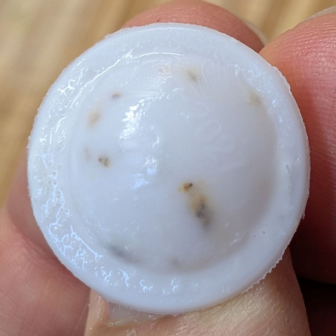
The seal was firmly affixed inside the cap, just like all the seals on all the other cartons we’ve ever bought, so this wasn’t a “broken seal”.
The bottom of the seal looked about the same:
Hood Heavy Cream seal – interior 1
The cream inside the carton looked & smelled fine, so it went into the morning omelette with no ill effect. Yes, I’m aware some bacterial contamination has no particular smell or taste.
Scraping off the pure-white cream showed the crud had been molded inside the plastic:
Hood Heavy Cream seal – interior 2
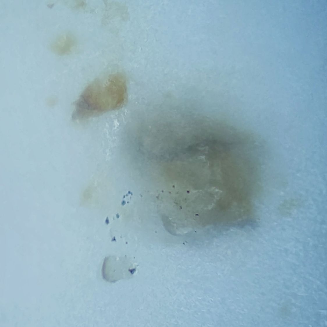
A closer look at the exterior surface of the seal:
Hood Heavy Cream seal – exterior detail
And the interior surface:
Hood Heavy Cream seal – interior detail
Both of those are focused on the top surface; the blurred areas are inside the plastic.
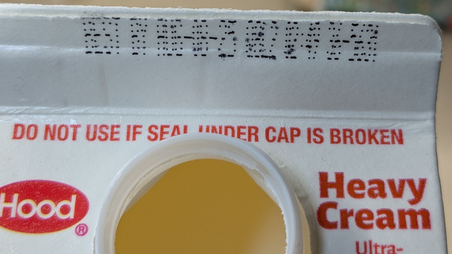
The date & production codes sprayed onto the carton were somewhat illegible:
Hood Heavy Cream seal – illegible codes
Getting a better angle helped:
Hood Heavy Cream seal – date prod codes
I sent in a report, but I’m sure I’ll never know the rest of the story …
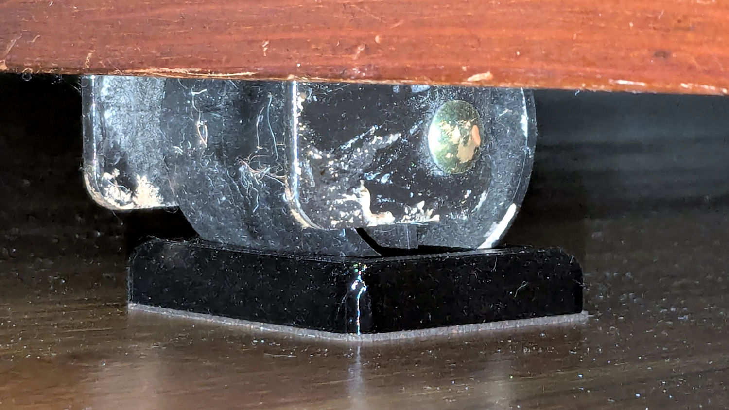
The upstairs Sewing Room came with a couch-like bed incorporating a roll-out trundle bed. It doesn’t get a lot of use, but it lacks wheel locks and tends to scoot away unless you get into it rather more carefully than seems reasonable.
So I made a pair of stops to capture the wheels:
Rolling Bed Stops – installed
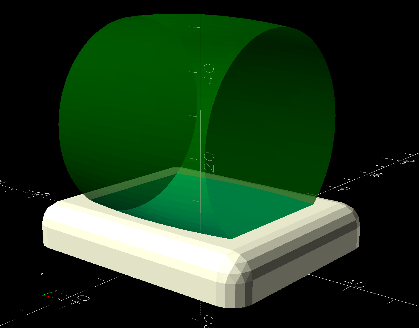
The solid model shows they’re just plastic blocks minus a model of the roller wheel:
Rolling Bed Stops – solid model – show view
I like the wood-grain effect of the doubly curved recess on printed plastic layers, even if nobody will ever see it:
Rolling Bed Stops – PrusaSlicer
The OpenSCAD code also exports a projection of the block as an SVG file to laser-cut the cork pad.
Roll the trundle bed into position, push the stops against the wheels, lift and pull forward an inch, let it down, and the wheels snap into those recesses.
These are considerably fancier than some of the other wheel stops / feet around the house, if only because I got to use the Chord Equation to solve for the radius of the circle parallel to the axle for a snug socket.
This file contains hidden or bidirectional Unicode text that may be interpreted or compiled differently than what appears below. To review, open the file in an editor that reveals hidden Unicode characters.
Learn more about bidirectional Unicode characters
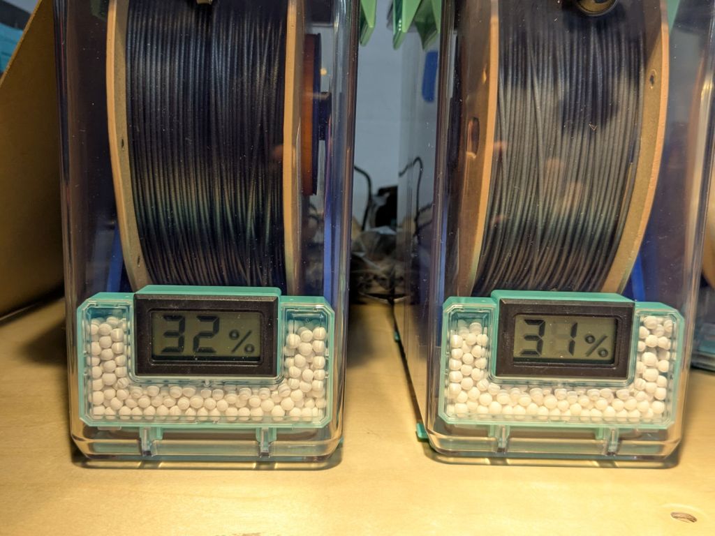
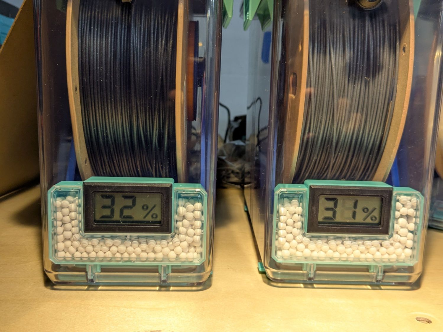
A pair of PolyDryer boxes has been holding black and gray PETG-CF for a while:
PolyDryer – PETG-CF – 32 pctRH Black 31 pctRF Gray
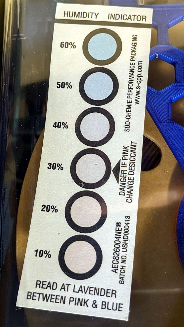
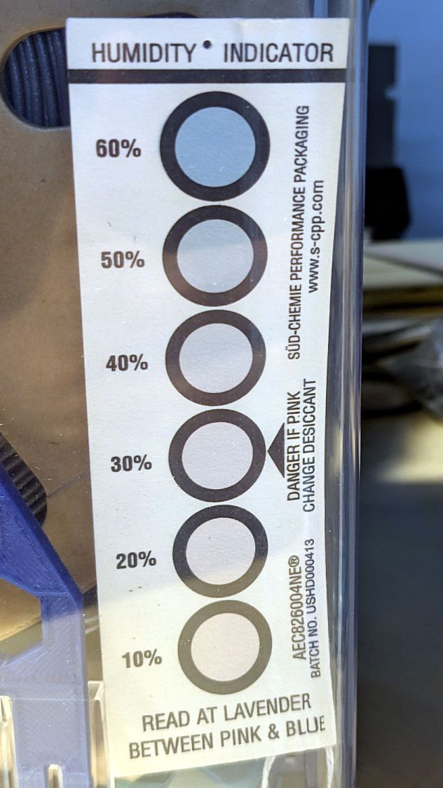
A few days ago I slipped humidity indicator cards into the boxes:
The black PETG-CF card suggests 30 to 40 %RH:
PolyDryer – PETG-CF – 32 pctRH Black test card
Yes, I dropped that card into the box upside-down.
The gray PETG-CF card shows similar results:
PolyDryer – PETG-CF – 31 pctRF Gray test card
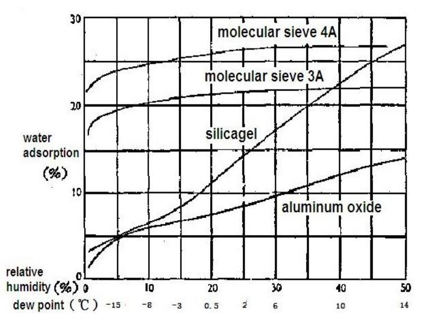
The desiccant in the black PETG-CF box weighed 80.9 g, a gain of 5.9 g = 10.8%. The chart suggests that corresponds to 35 to 40 %RH:
Desiccant adsorption vs humidity
The gray PETG-CF box had 102.0 g of desiccant. I apparently loaded 25 g in the meter container and 70 g in seven tea bags, but I don’t trust those numbers enough to go any further.
Unlike the black PETG box mismatch, these black PETG-CF numbers seem plausible. The results may depend on allowing far more time for the filament + air to equilibrate with the desiccant tucked in its containers than the days I’ve been giving it.
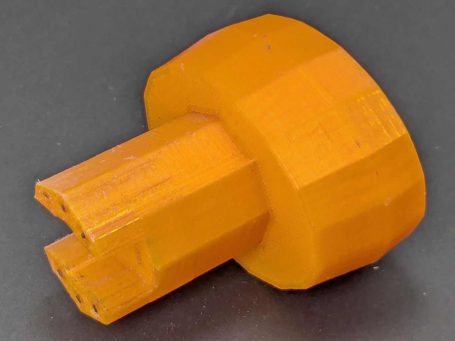
Mary found the wrench I made five years ago in the bottom of her tool bucket:
Hose Valve Knob – five years later
Having moved away from the garden with all the valves that wrench turned, it can now go into the 3D Printed Sample Box for use in the unlikely event I ever give another talk on the subject.
I’d design it differently these days, what with BOSL2 in my sails, but it got the job done.
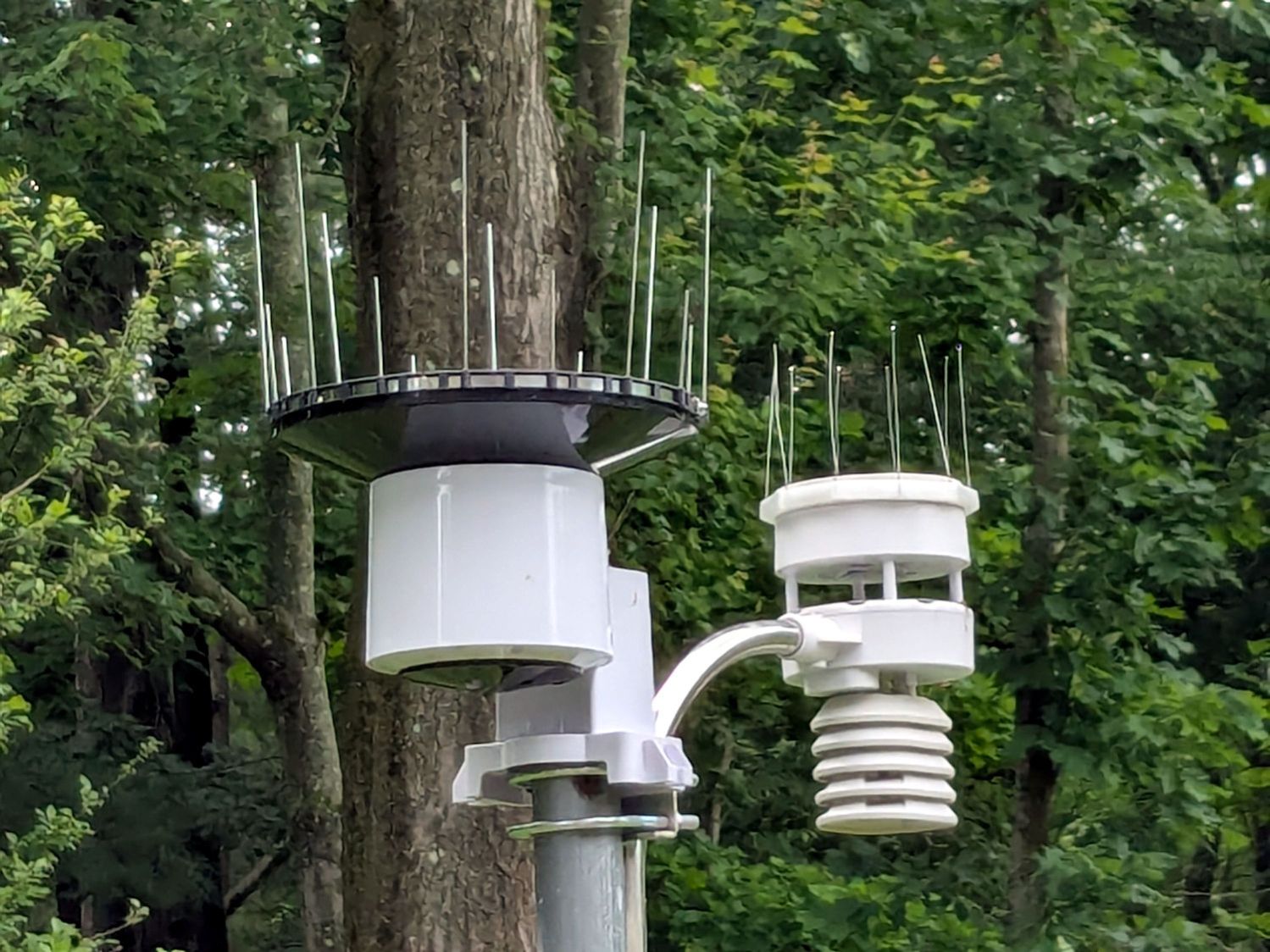
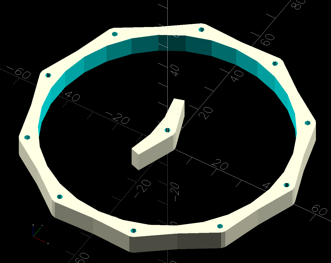
A critter made off with our battered plastic rain gauge, so I set up an Ambient Weather WS-5000 station to tell Mary how much rain her garden was getting. I added the Official Bird Spike Ring around the rain gauge to keep birds off, but robins began perching atop the anemometer while surveying the yard and crapping on the insolation photocell.
After a few false starts, the anemometer now has its own spikes:
Weather station with additional spikes
It’s a snugly fitting TPU ring:
Weather Station Spikes – build test piece
The spikes are Chromel A themocouple wire, because a spool of the stuff didn’t scamper out of the way when I opened the Big Box o’ Specialty Wire. As you can tell from the picture, it’s very stiff (which is good for spikes) and hard to straighten (which is bad for looking cool).
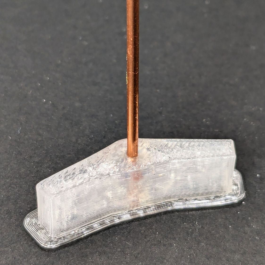
The shape in the middle is a hole diameter test piece. Next time around, I’ll use thicker 14 AWG copper wire:
Weather station spikes – test piece
The test piece showed I lack good control over the TPU extrusion parameters on the Makergear M2, as holes smaller than about 2 mm vanish, even though the block’s outside dimensions are spot on. This application wasn’t too critical, so I sharpened the wire ends and stabbed them into the middle of the perimeter threads encircling the hole.
This file contains hidden or bidirectional Unicode text that may be interpreted or compiled differently than what appears below. To review, open the file in an editor that reveals hidden Unicode characters.
Learn more about bidirectional Unicode characters