Ed Nisley's Blog: Shop notes, electronics, firmware, machinery, 3D printing, laser cuttery, and curiosities. Contents: 100% human thinking, 0% AI slop.
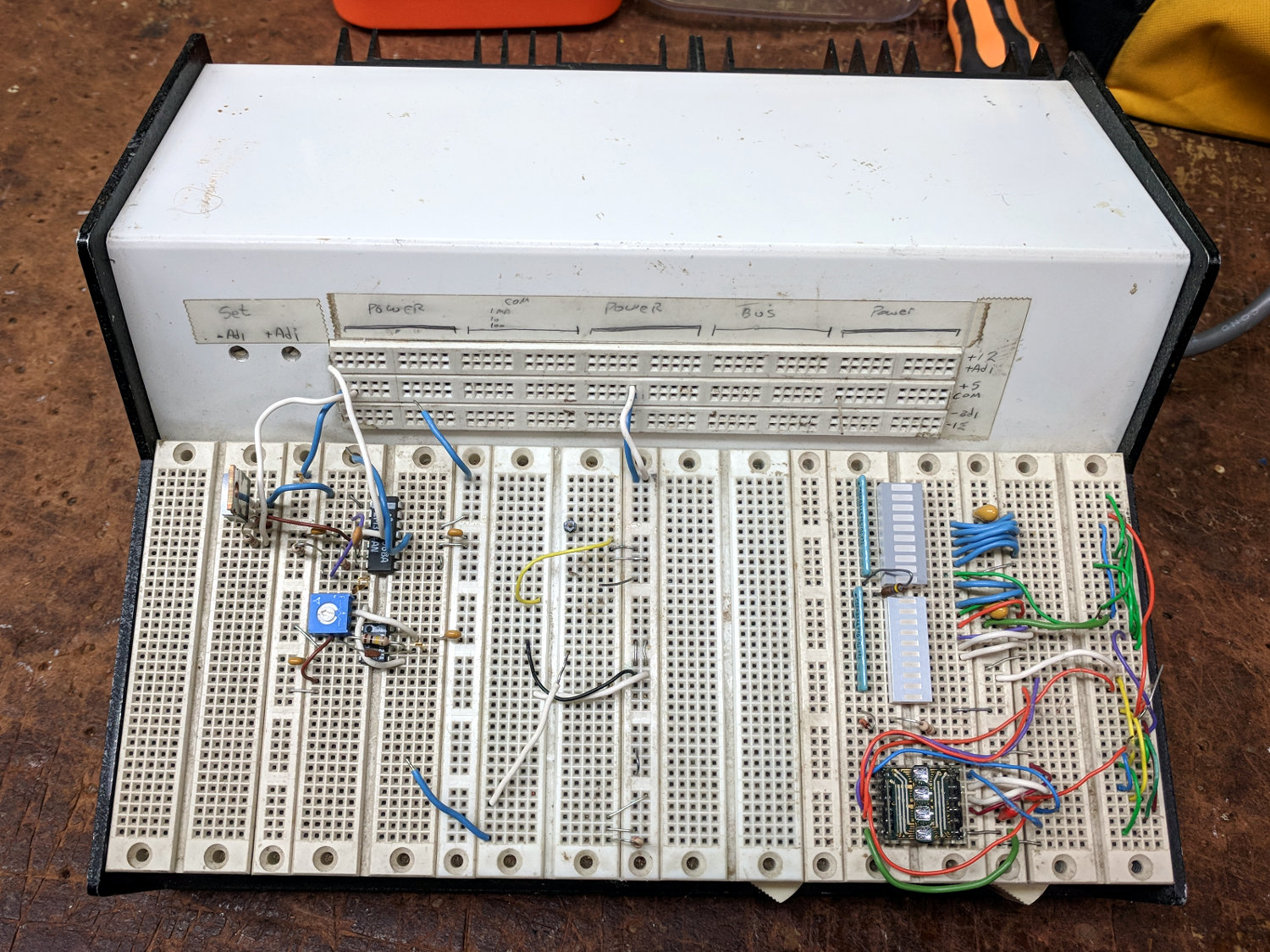
One of my very first projects, after setting up my very first home shop in our very first home, was building an overly elaborate prototype board with five (!) linear power supplies:
Proto Board – overview
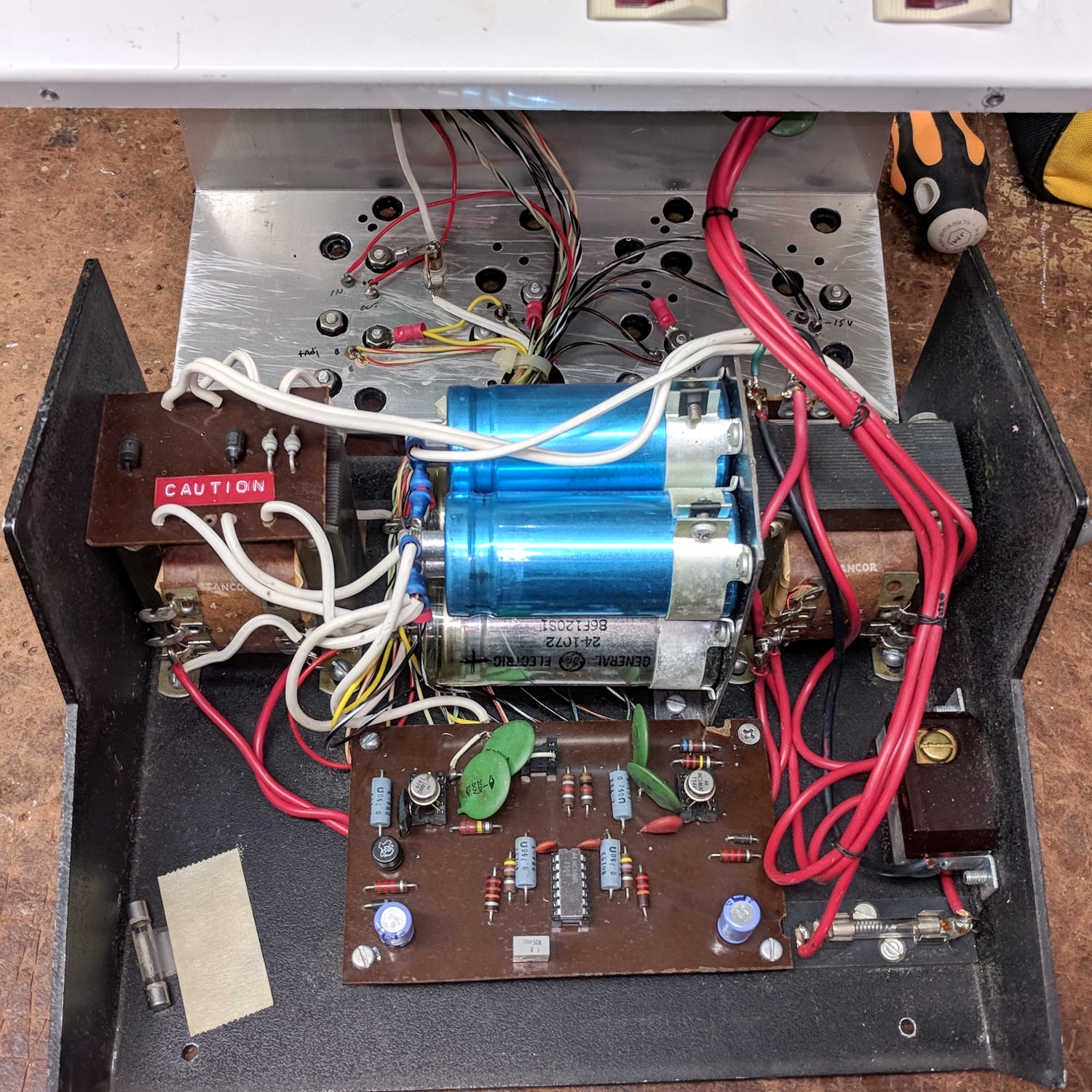
The components come from the mid-70s and the shop happened around 1980, so it’s been ticking along for nigh onto four decades. Of late, the supply voltages became erratic and I eventually popped the top:
Proto Board – innards
Yeah, linear pass transistor regulators driven from bulk cap storage, hand-hewn bridge rectifiers, and multi-tap transformers. Everything mounts on screws tapped into the 1/8 inch aluminum chassis, with power transistors on a huge finned heatsink attached to the rear panel. The thing weighs 11.6 pounds = 5.3 kg.
Not a trace of firmware to be found. Heck, surface-mount components hadn’t yet come into common use.
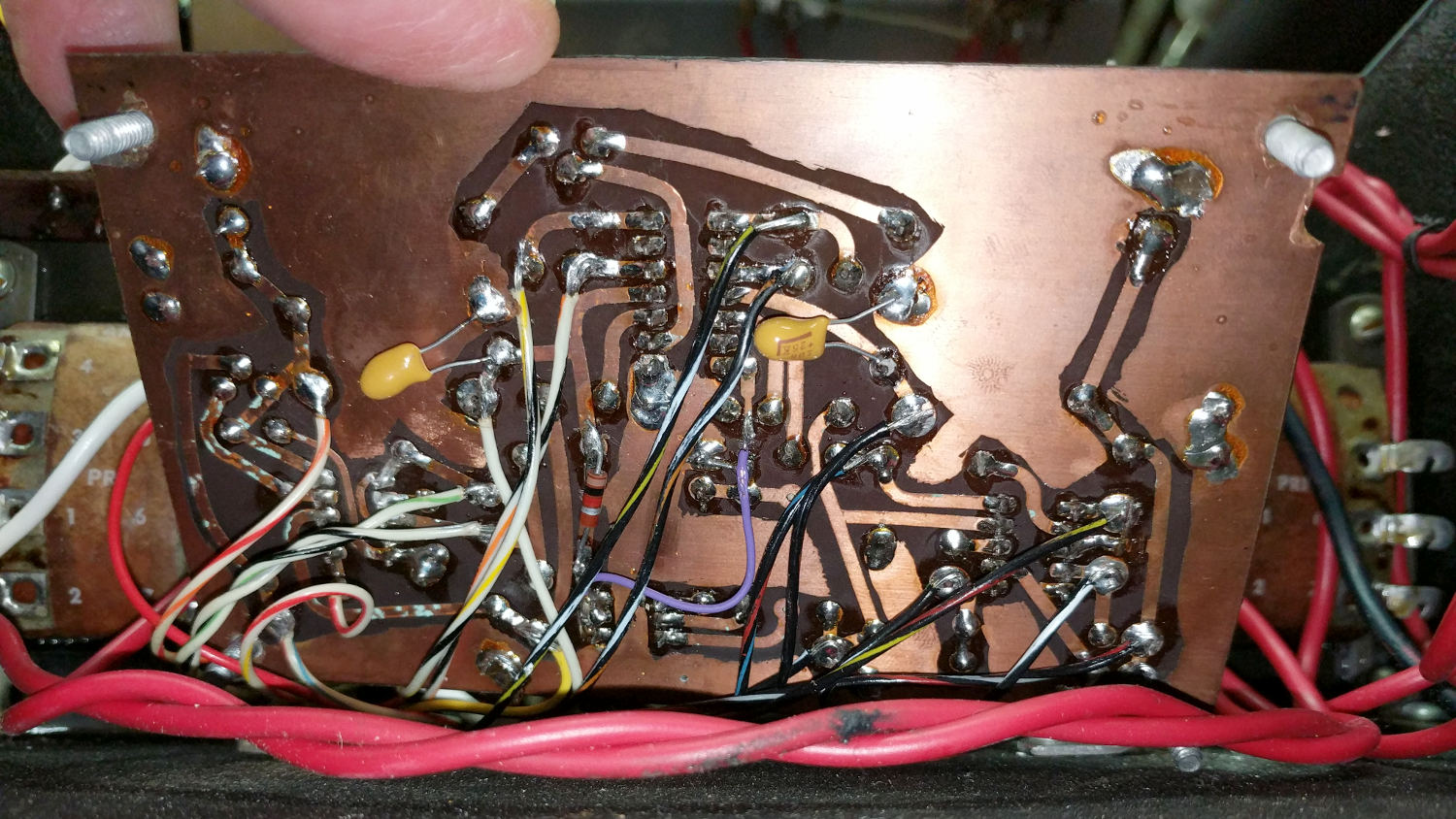
The circuitry lives on a crudely etched phenolic board:
Proto Board – etched circuit board
There may be a schematic somewhere in my collection, but it hasn’t surfaced in a long time. I’m mildly surprised I didn’t tuck it inside the case, which may have been a life lesson yet to be learned.
Based on my recent experience with the Tek AM503, I wiggled the two metal-can regulators and the ceramic (!) regulator, gingerly plugged in the line cord, flipped the switch, and all the supply voltages once again work perfectly.
Whiteboards from the SqWr Electronics Session 5, covering transistors as switches …
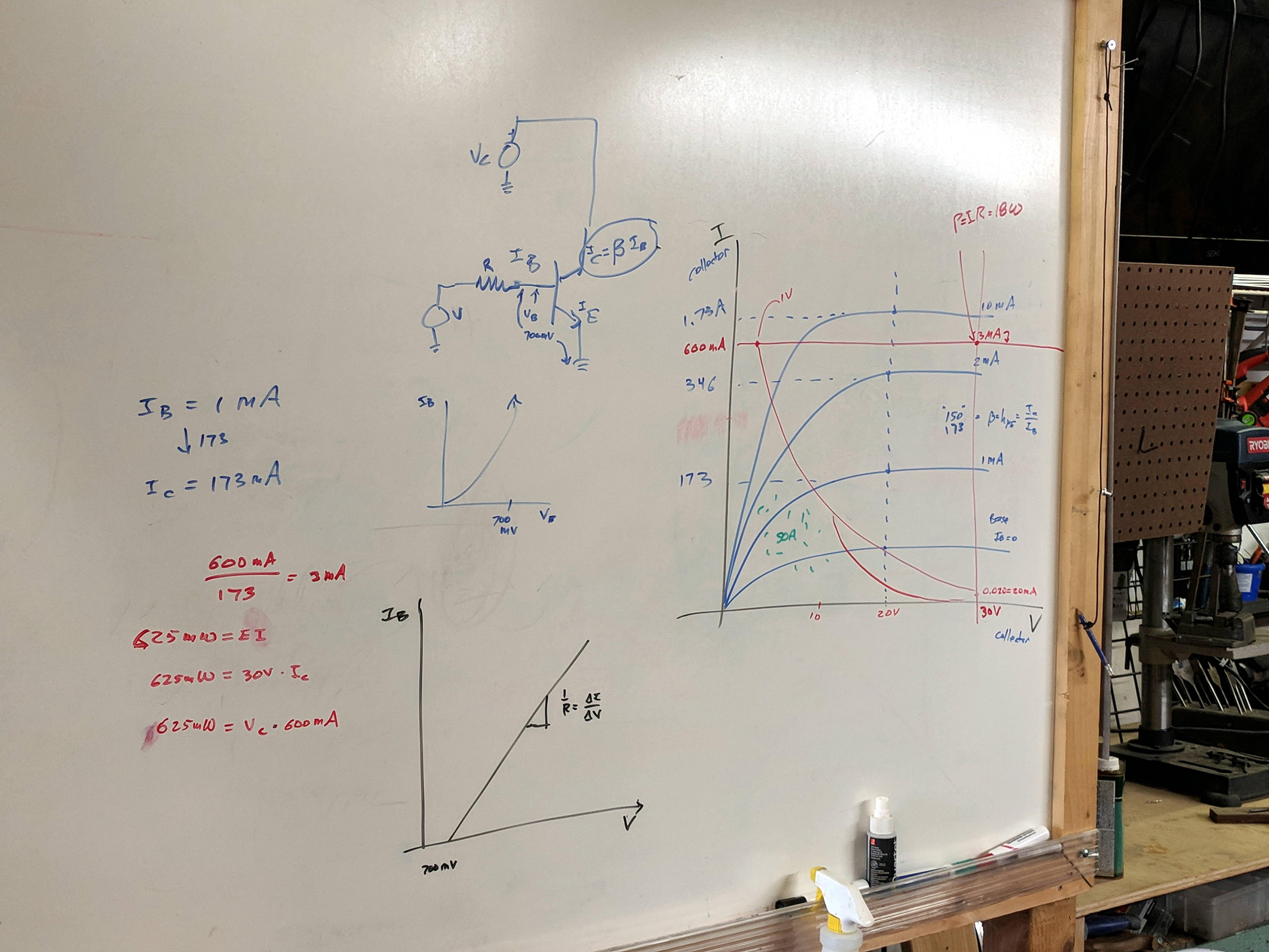
Reviewing I vs V plots, starting with a resistor and then a transistor as a current amplifier:
SqWr Electronics 5 – whiteboard 1
Reminder of why you can’t run a transistor at its maximum voltage and current at the same time:
SqWr Electronics 5 – whiteboard 2
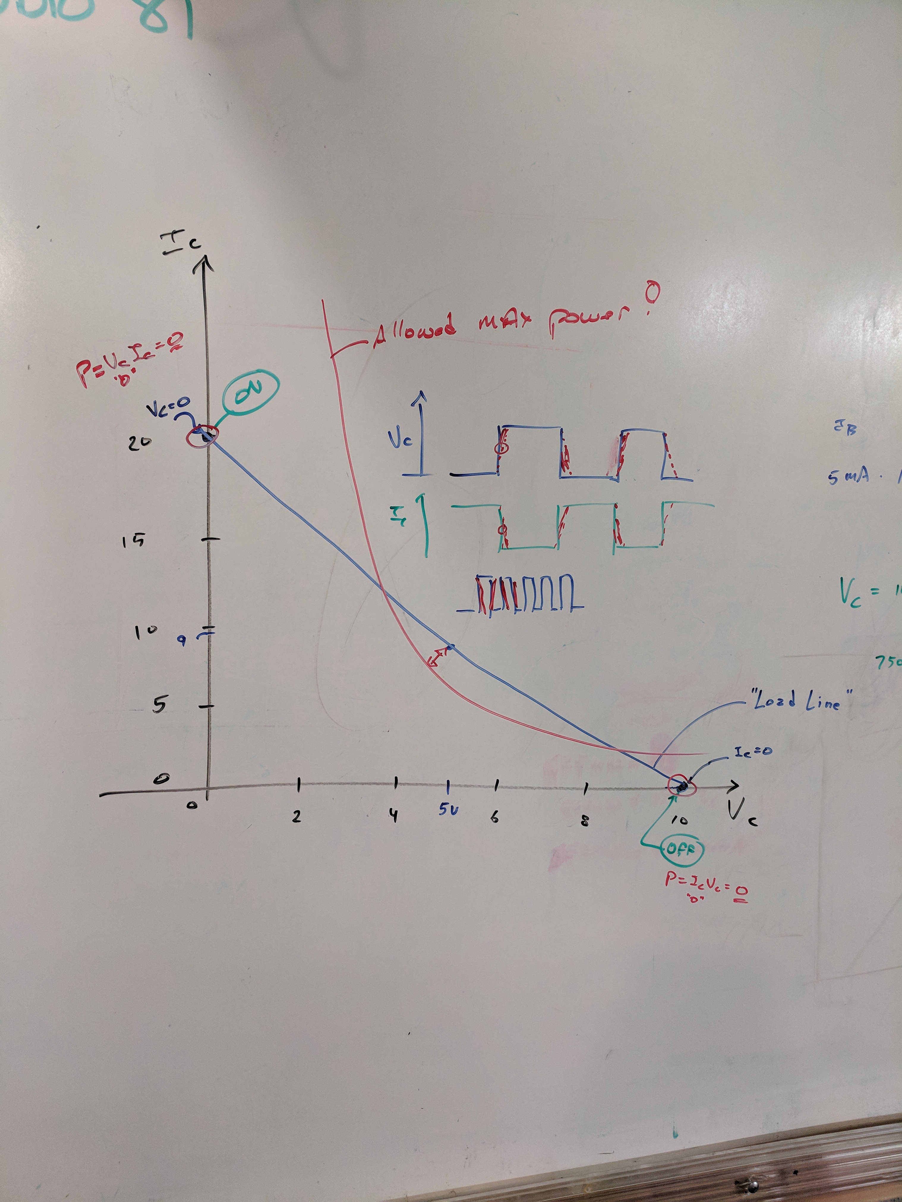
A resistor load line, with power calculation at the switch on and off coordinates:
SqWr Electronics 5 – whiteboard 3
Detail of the power calculations, along with a diagram of the current and voltage when you actually switch the poor thing:
SqWr Electronics 5 – whiteboard 3 detail
Oversimplification: most of the power happens in the middle, but as long as the switching frequency isn’t too high, it’s all good.
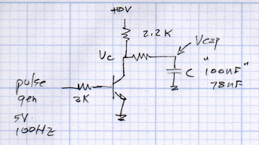
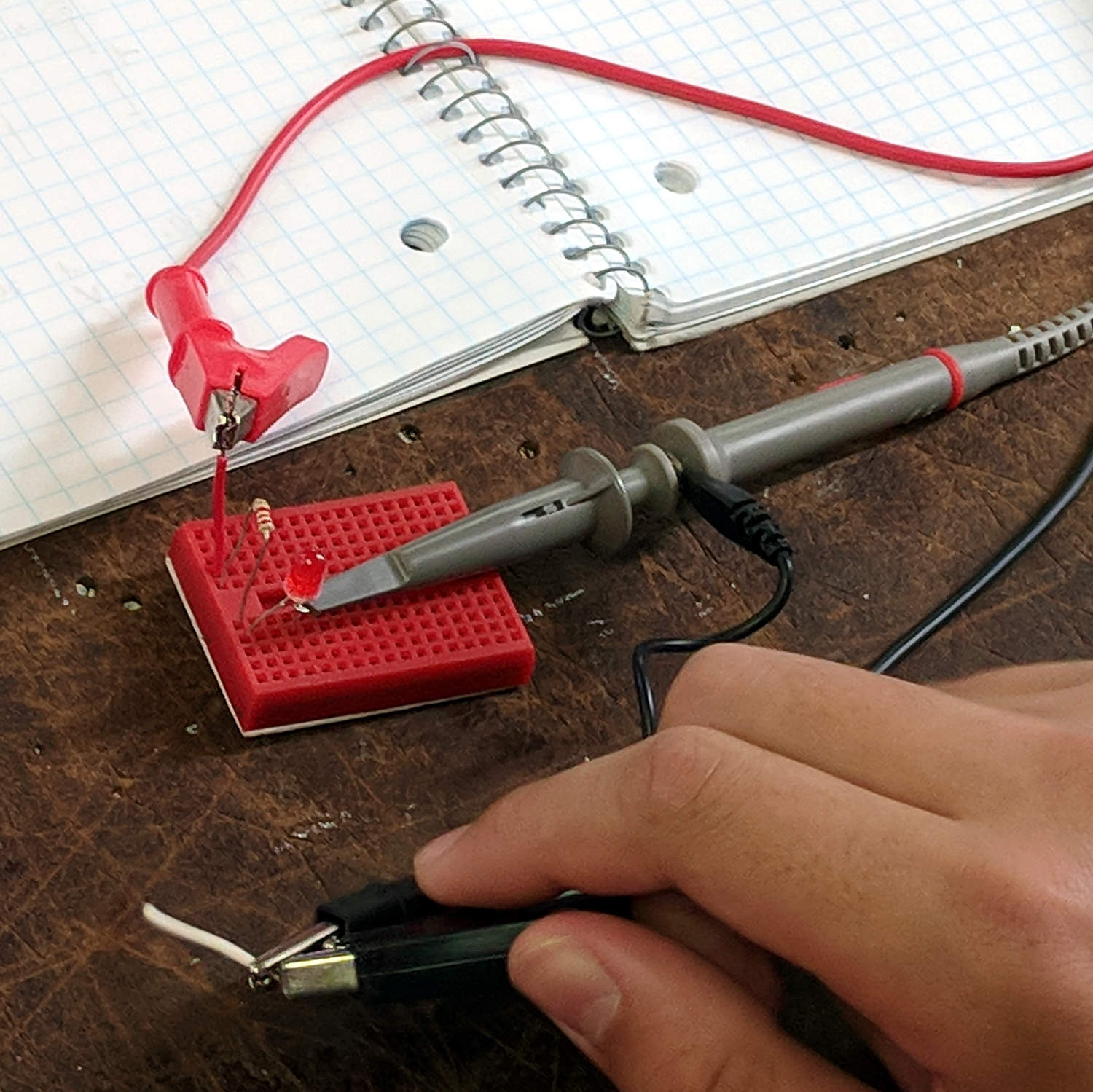
Schematic of the simplest possible switched LED circuit, along with a familiar mechanical switch equivalent:
SqWr Electronics 5 – whiteboard 4
We started with the “mechanical switch” to verify the connections:
SqWr Session 5 – Switched LED breadboard
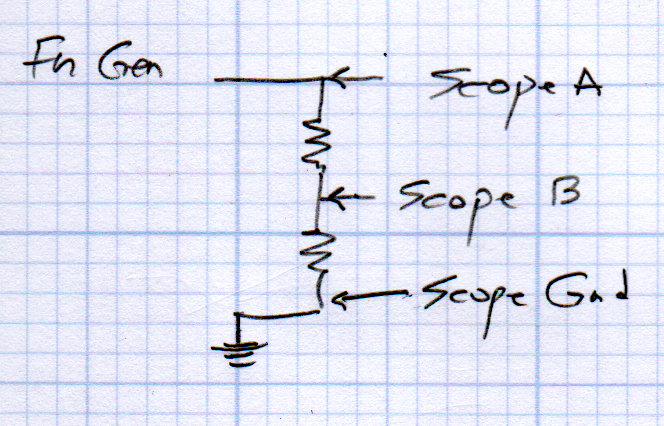
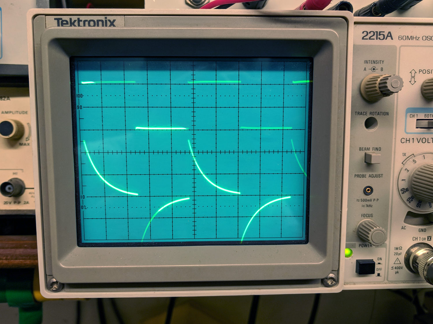
Building the circuitry wasn’t too difficult, but covering the function generator and oscilloscope hookup took far more time than I expected.
My old analog Tek 2215 scope was a crowd-pleaser; there’s something visceral about watching a live CRT display you just don’t get from the annotated display on an LCD panel.
I’d planned to introduce capacitors, but just the cap show-n-tell went well into overtime. We’ll get into those in Session 6, plus exploring RC circuitry with function generators and oscilloscopes.
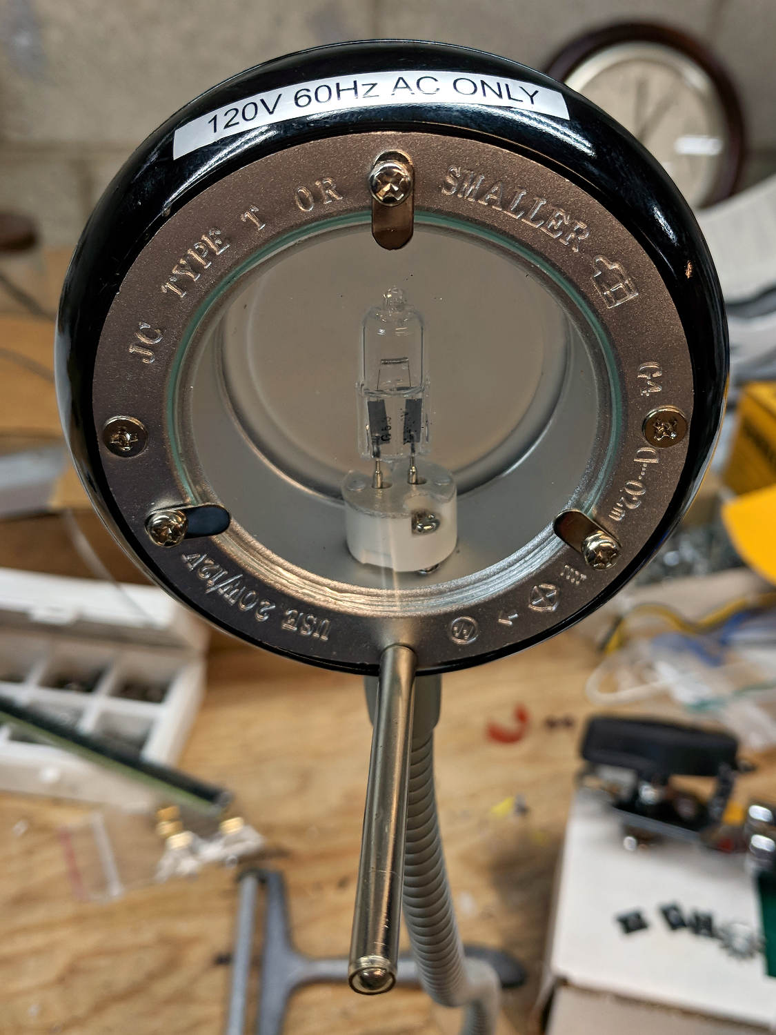
A discarded 20 W halogen desk lamp arrived in the Basement Laboratory for rebuilding:
Halogen Desk Lamp – head layout
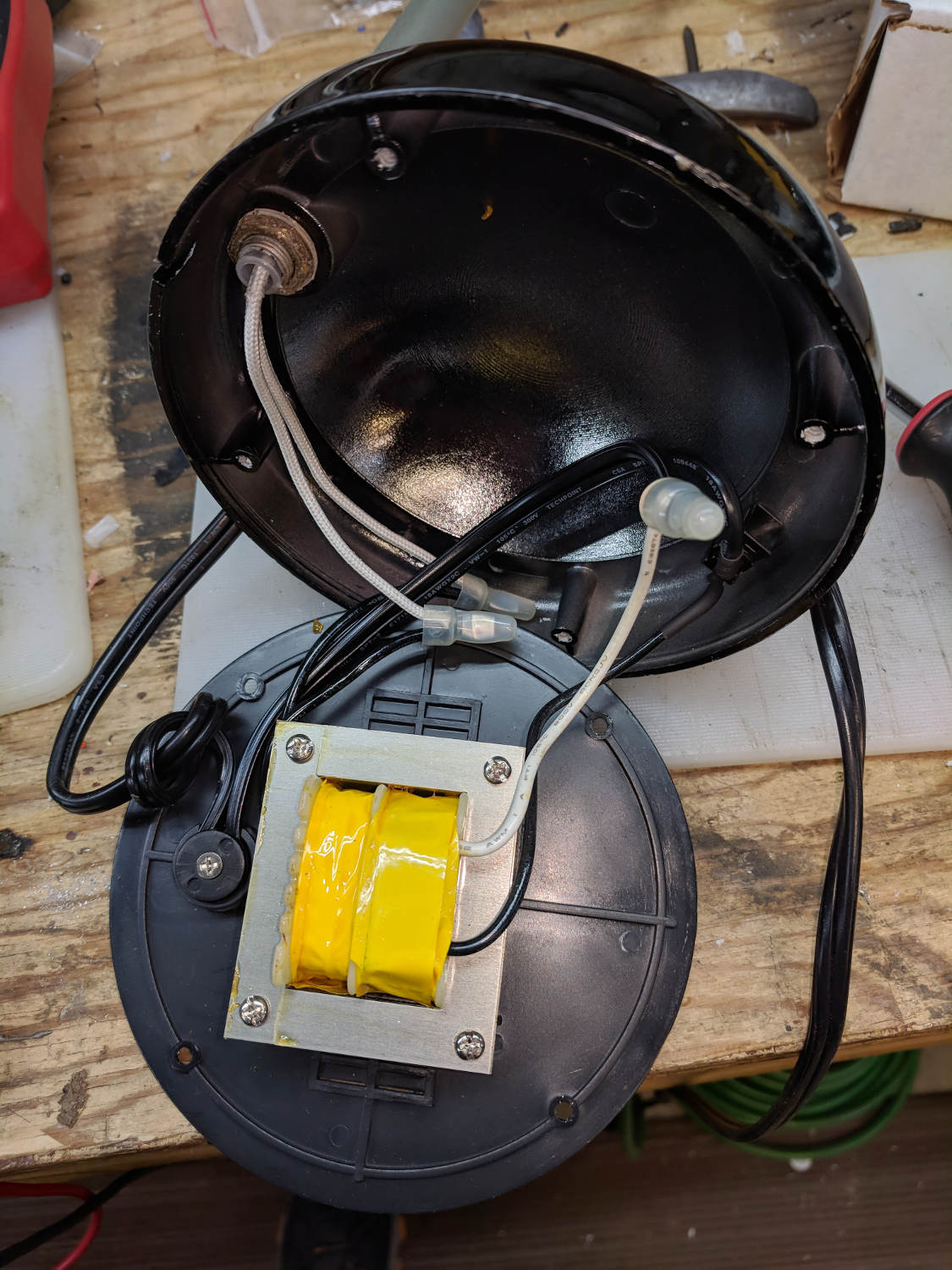
An incandescent bulb doesn’t care about AC or DC, so a simple transformer also serves as a counterweight in the base:
Halogen Desk Lamp – 12 V 20 W transformer
I might replace it with some steel sheets, although I have no immediate need for a bare transformer.
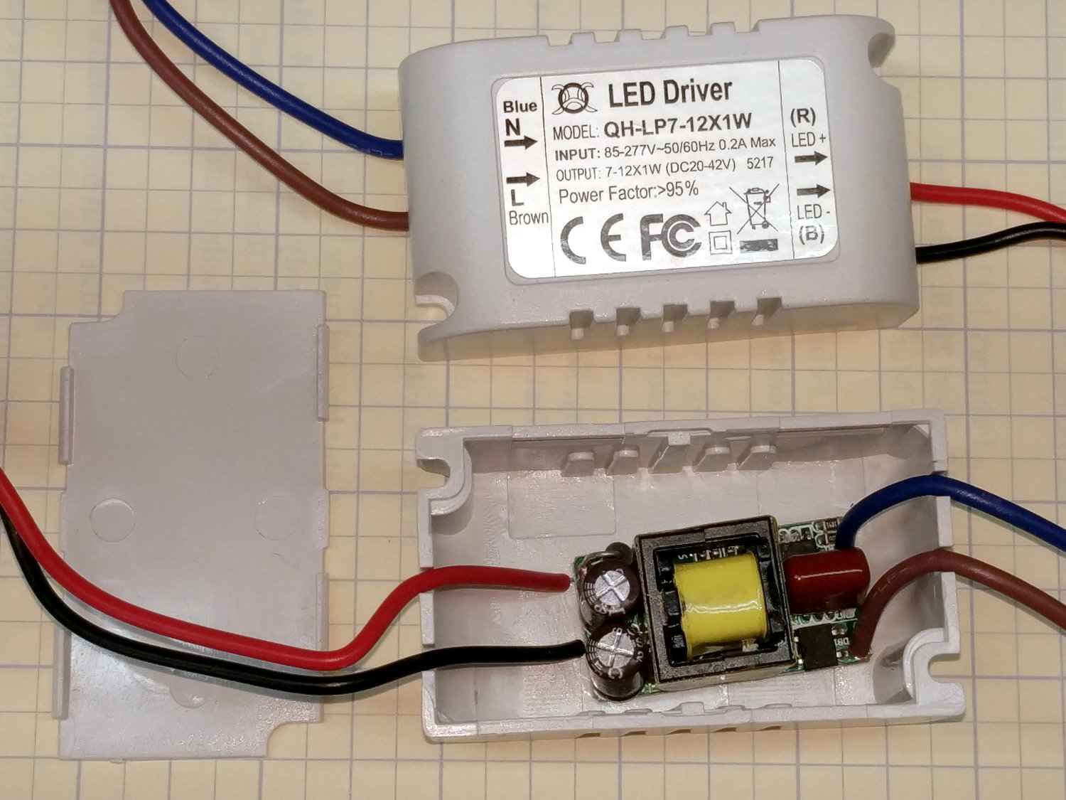
A case adds 19¢ to each 10 W 300 mA LED driver:
Halogen Desk Lamp – 10 W LED driver innards
Nice strain relief on those line-voltage wires, eh?
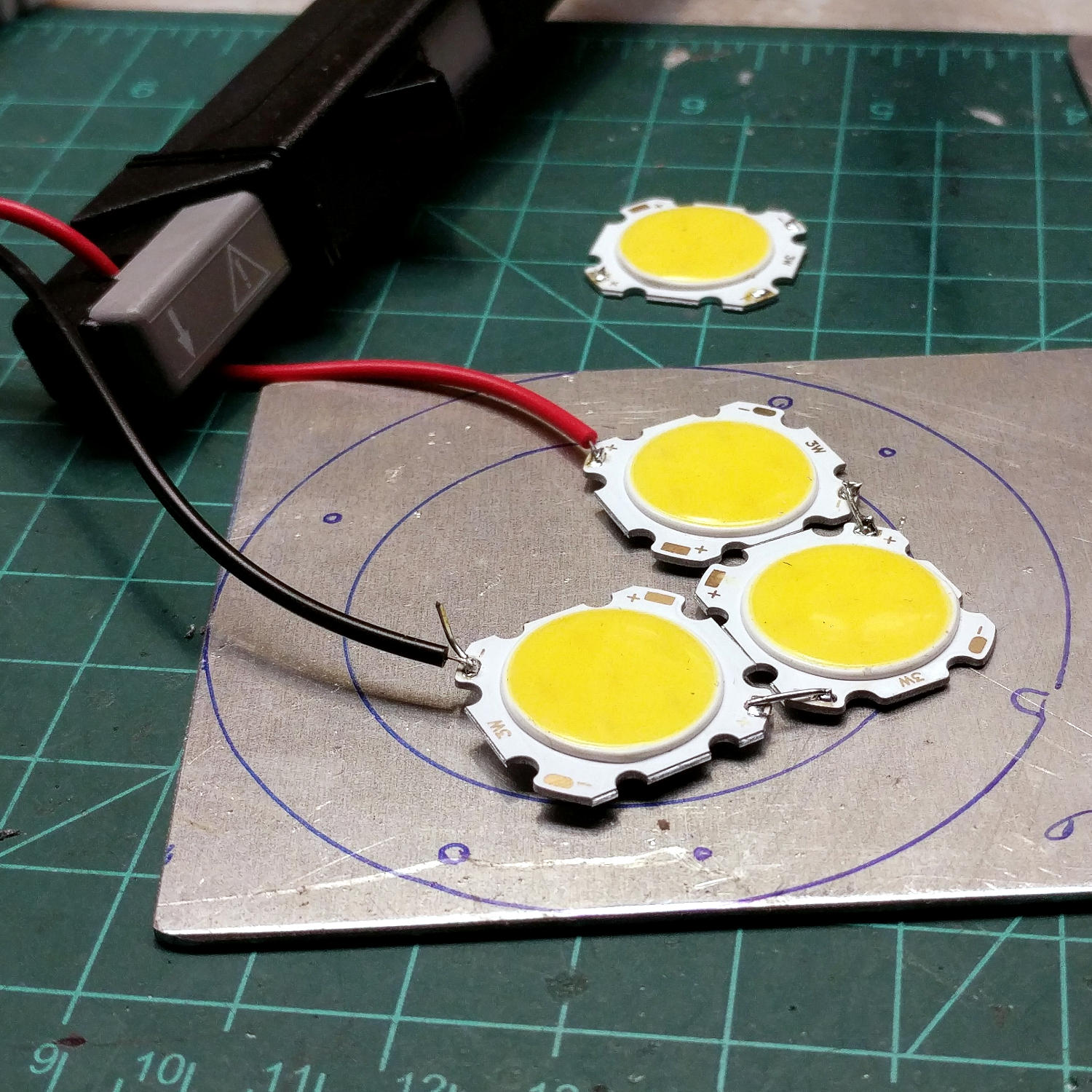
A simple test setup with three 3 W COB LED panels:
Halogen Desk Lamp – 3x3W COB LED test
I clamped them to the aluminum sheet for heatsinking before I lit ’em up. The circles traced directly from the lamp’s hardware give some idea of the eventual layout.
I have more-intense LEDs, but spreading the light over a larger area should work better for the intended purpose. These are pleasant warm-white LEDs, too.
The fourth LED raised the forward voltage beyond the supply’s 42 V maximum, causing the supply to blink on and off.
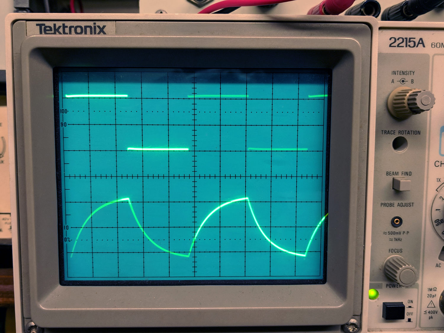
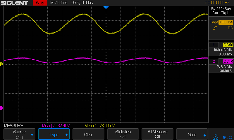
Much to my surprise, the driver has plenty of 60 Hz ripple:
COB LED 3x3W – 10 W driver – 100 mA-div 10 V-div
The top trace averages 280 mA and the bottom trace 32 V, so the LEDs run at 9 W = 3 W apiece, as they should.
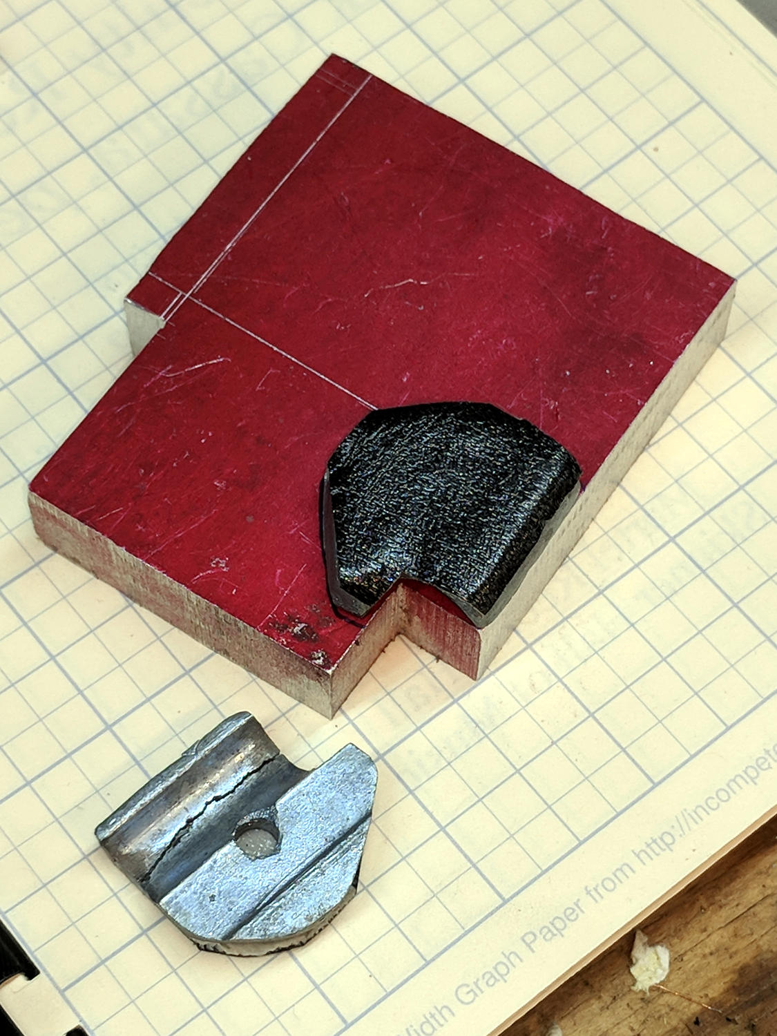
The clamp holding the magnifying lamp (with a fluorescent ring light!) over the Basement Laboratory Desk finally fractured:
Magnifying Lamp Pivot – broken parts
Gorilla Tape held the broken parts together well enough to determine how it used to work:
Magnifying Lamp Pivot – hole sizing
The two parts used to be 11.2 mm thick, but it fit on a random chunk of half-inch aluminium plate so perfectly as to constitute a Good Omen:
Magnifying Lamp Pivot – stock layout
I decided the saw kerf would make up the difference, because, sheesh, we’re talking pot metal here.
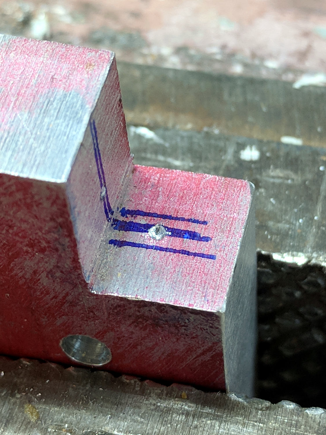
Lay out the center, use a transfer punch the same diameter as the lamp pivot to get the proper spacing, give it a whack:
Magnifying Lamp Pivot – hole marking
The alert reader will note I came that close to drilling the hole through the wrong side of the angle.
And, yes, extrapolating the vertical edge downward suggests the large hole-to-be will intersect the small hole-in-being. This is deliberate: the clamp screw through the smaller hole fits into a recess around the lamp pivot shaft to keep it from sliding to-and-fro. I had to convince myself, but it really did work out OK.
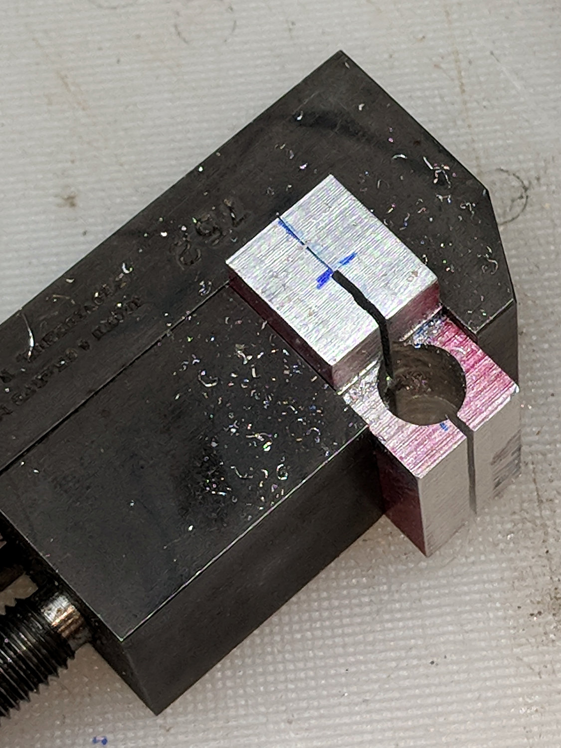
Pay some attention to clamping it at right angles to the spindle so the big hole goes through more-or-less in the right direction:
Magnifying Lamp Pivot – drill press alignment
The masking tape serves as a depth reminder:
Magnifying Lamp Pivot – drilling
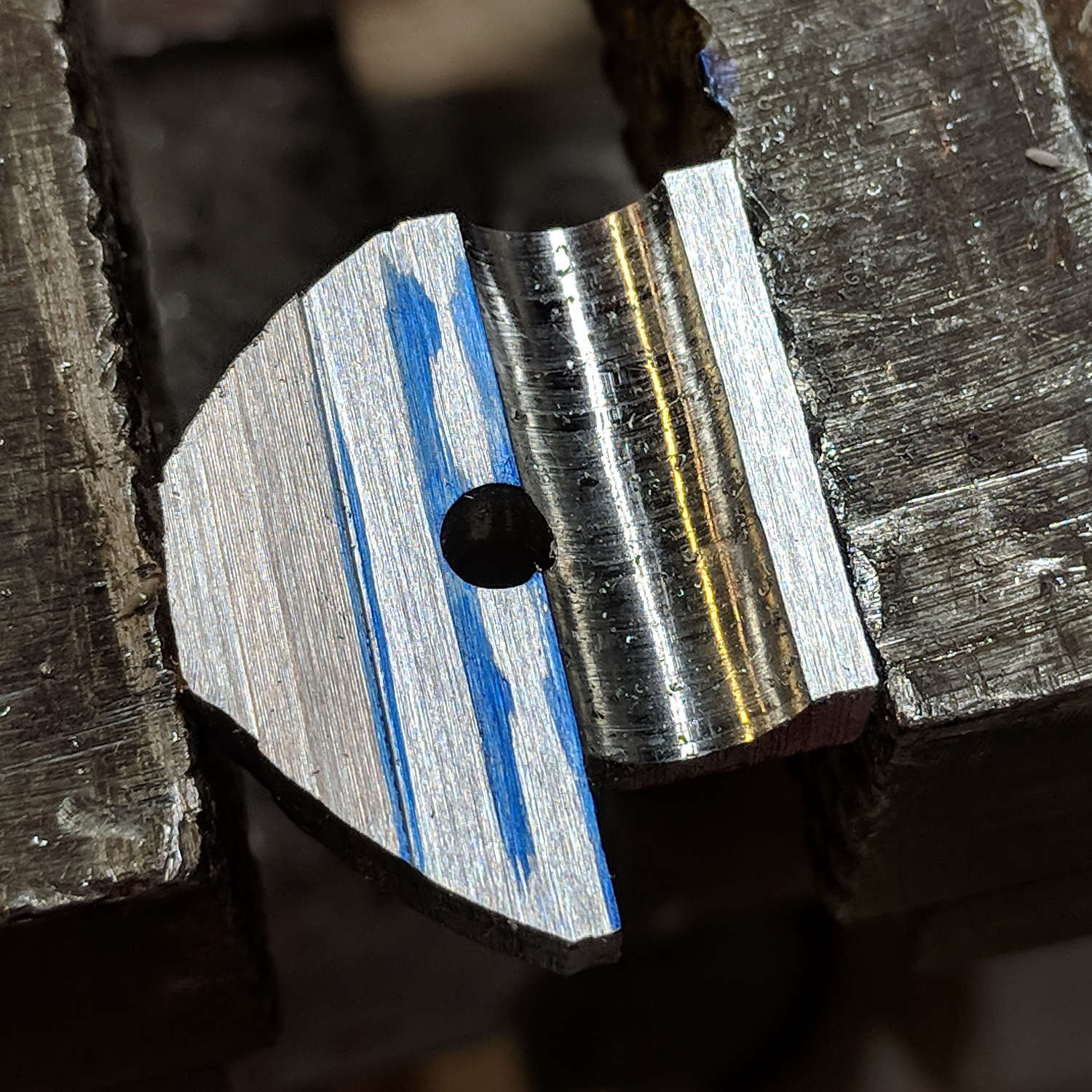
Set it up in a machinist’s clamp, bandsaw in twain, file the kerf reasonably flat, clamp the halves together, then bandsaw the clearance slot:
Magnifying Lamp Pivot – clearance slot
The clearance kerf wasn’t nearly as on-center as I wanted, which doesn’t really matter, but I filed a bit more diligently on the shallow side while clearing up the slot:
Magnifying Lamp Pivot – clearance filing
Introducing the new parts to Mr Disk Sander roundified them enough to pass inspection. These angular bits obviously require a bit more attention to detail:
Magnifying Lamp Pivot – parts
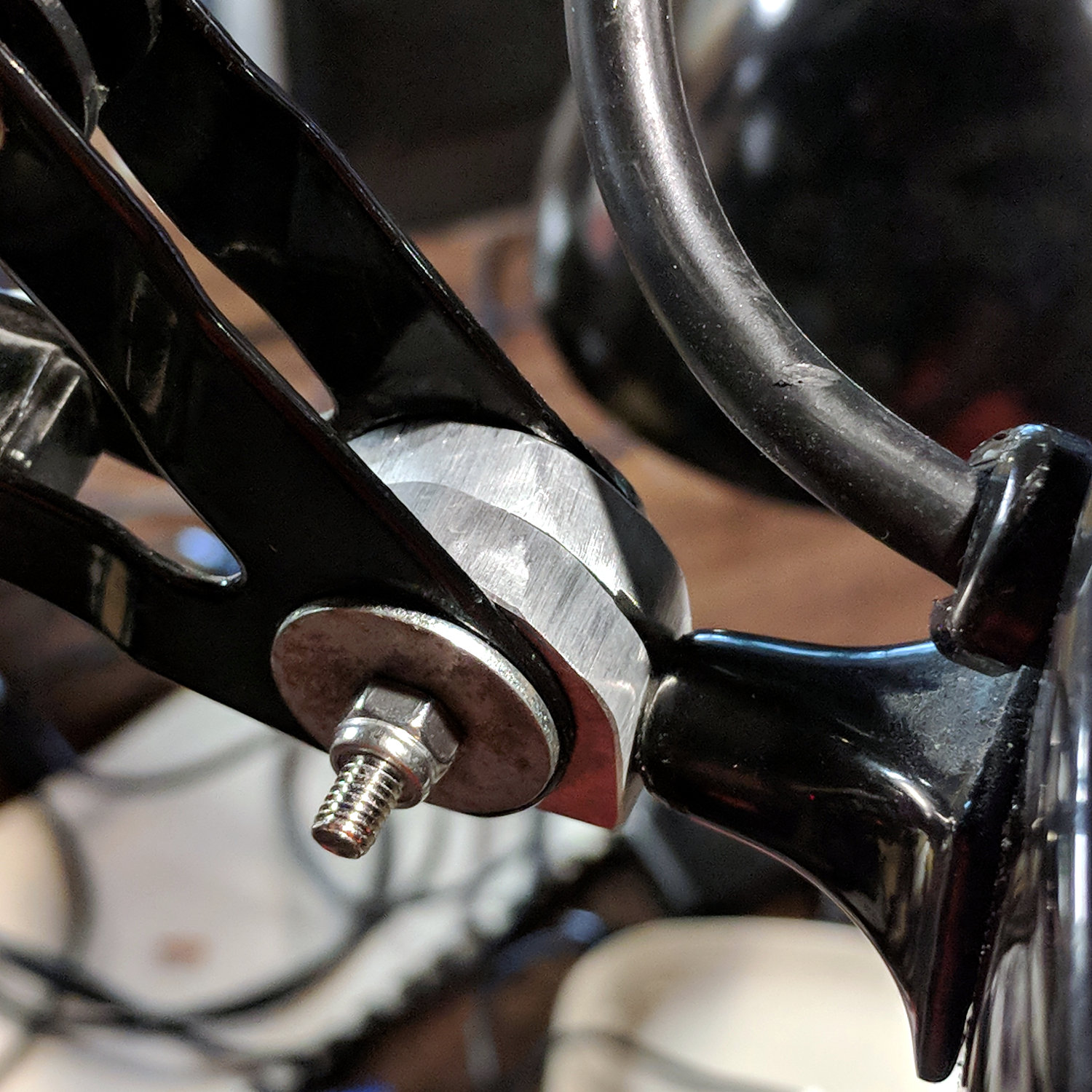
The lamp originally had a fancy knob on the screw which never worked particularly well, so I replaced it with a nylon locking nut to maintain a reasonable amount of pressure:
Magnifying Lamp Pivot – installed
The far end of the screw has a square shaft fitting into a square hole in the lamp arm, making it easy to torque the nut enough to make the pivot grip the shaft properly; if I ever find my Belleville washer stash again, I’ll add one. I should cut the screw off, too, but that’s definitely in the nature of fine tuning.
A pleasant morning of Quality Shop Time!
The obligatory doodle with dimensions, some of which turned out to be completely incorrect:
Back then, a 150 µF 450 V cap of the proper size (the 30 mm height being critical) was difficult to find and relatively expensive to purchase in onesies from the usual reliable sources, particularly as the repair advice I could find suggested it probably wasn’t the causing the monitor’s problems. So the monitor sat in pieces in an out-of-the-way corner of the Basement Laboratory while other events transpired.
As part of a long-delayed Great Cleanup of Small Projects, I discovered the caps are now four bucks delivered from halfway around the planet, so I got one, did the swap, reassembled the pieces, and the monitor works just like new. No pix, but you get the general idea.
For another few years, anyway.
For whatever reason, the 3.5 mm audio output seems dead. The monitor has a pair of teeny speakers that don’t do justice to its magnificent HDMI audio, but they’re entirely adequate for my simple needs: pre-SSH Raspberry Pi setup doesn’t call for much.