Ed Nisley's Blog: Shop notes, electronics, firmware, machinery, 3D printing, laser cuttery, and curiosities. Contents: 100% human thinking, 0% AI slop.
Having an ancient flip phone in need of a battery, I ordered a Kyocera TXBAT10133 battery from eBay. Described as “new” (which, according to the Ebay listing, means “New: A brand-new, unused, unopened, undamaged item in its original packaging”), I was somewhat surprised to see this emerging from the box:
Kyocera TXBAT10133 – not really new
It obviously led a rather hard life before being harvested from somebody else’s obsolete flip phone and is definitely not “new”.
Not yet having a deep emotional attachment to the thing, I set it up for a capacity test:
Kyocera TXBAT10133 – contact clamp
Given a very light 100 mA load, it shows about the same capacity as the original battery in our phone:
Kyocera TXBAT10133 – 2019-03-29
Given the precarious contact arrangement, the glitches near the right end aren’t surprising.
The battery label claims a 900 mA·h rating, so both have nearly their nominal capacity at such a reduced load. In actual use, the phone has a low battery after a few hours of power-on time, far less than when it was new.
The seller promises a replacement. For all I know, there are no genuinely “new” batteries available for these phones.
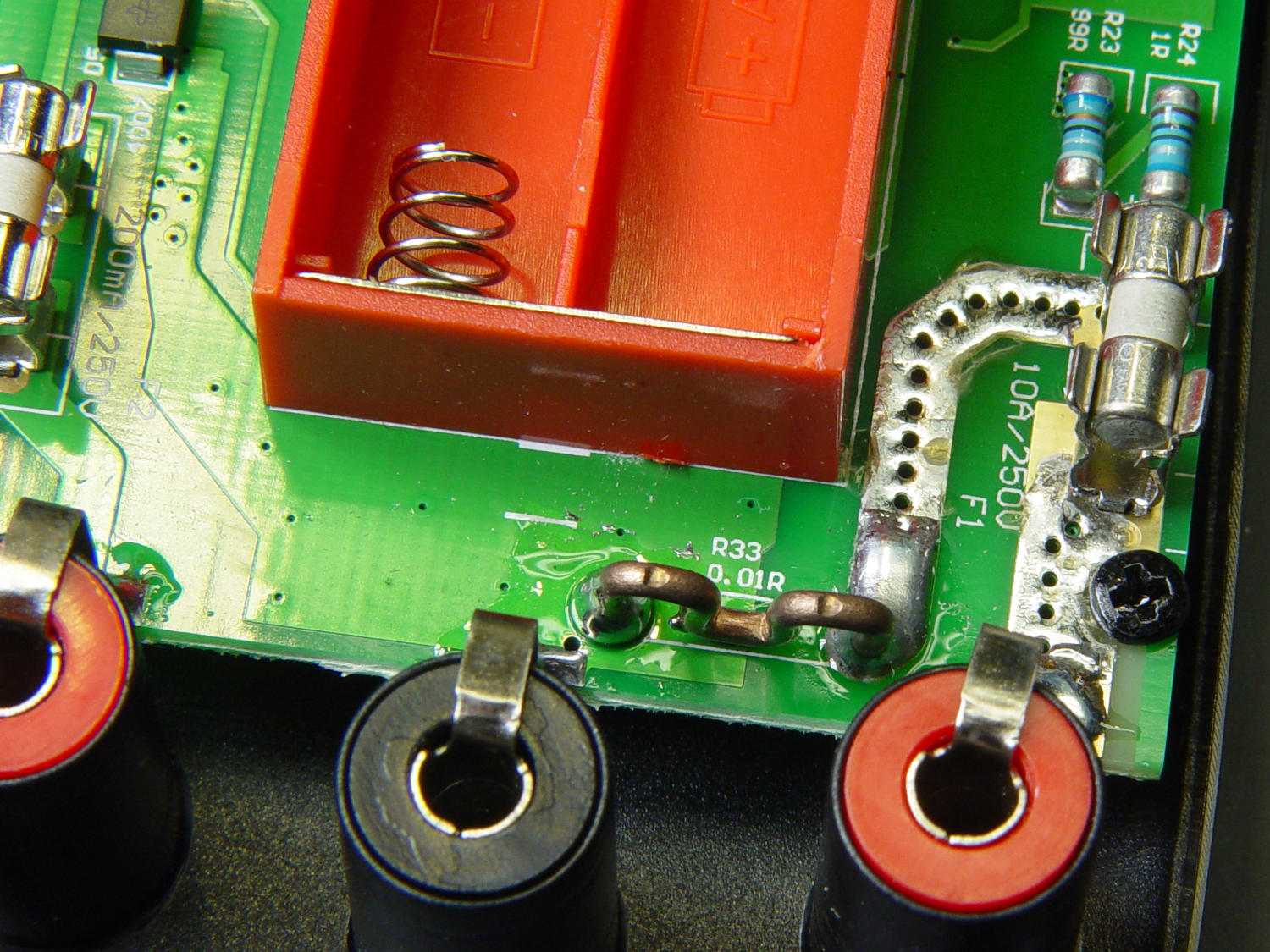
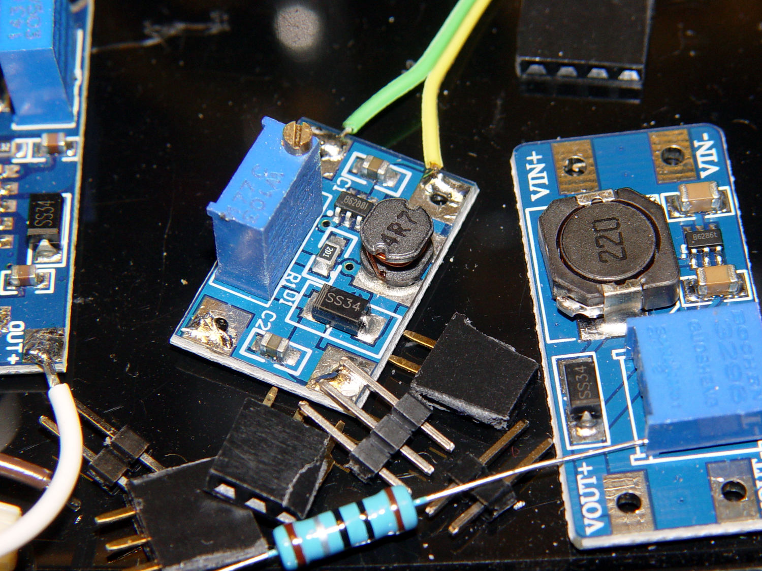
Somewhat to my surprise, Aneng AN8008/AN8009 multimeter PCBS sport what looks like a reasonably accurate current sense resistor on the 10 A input:
AN8009 10 A current shunt – top view
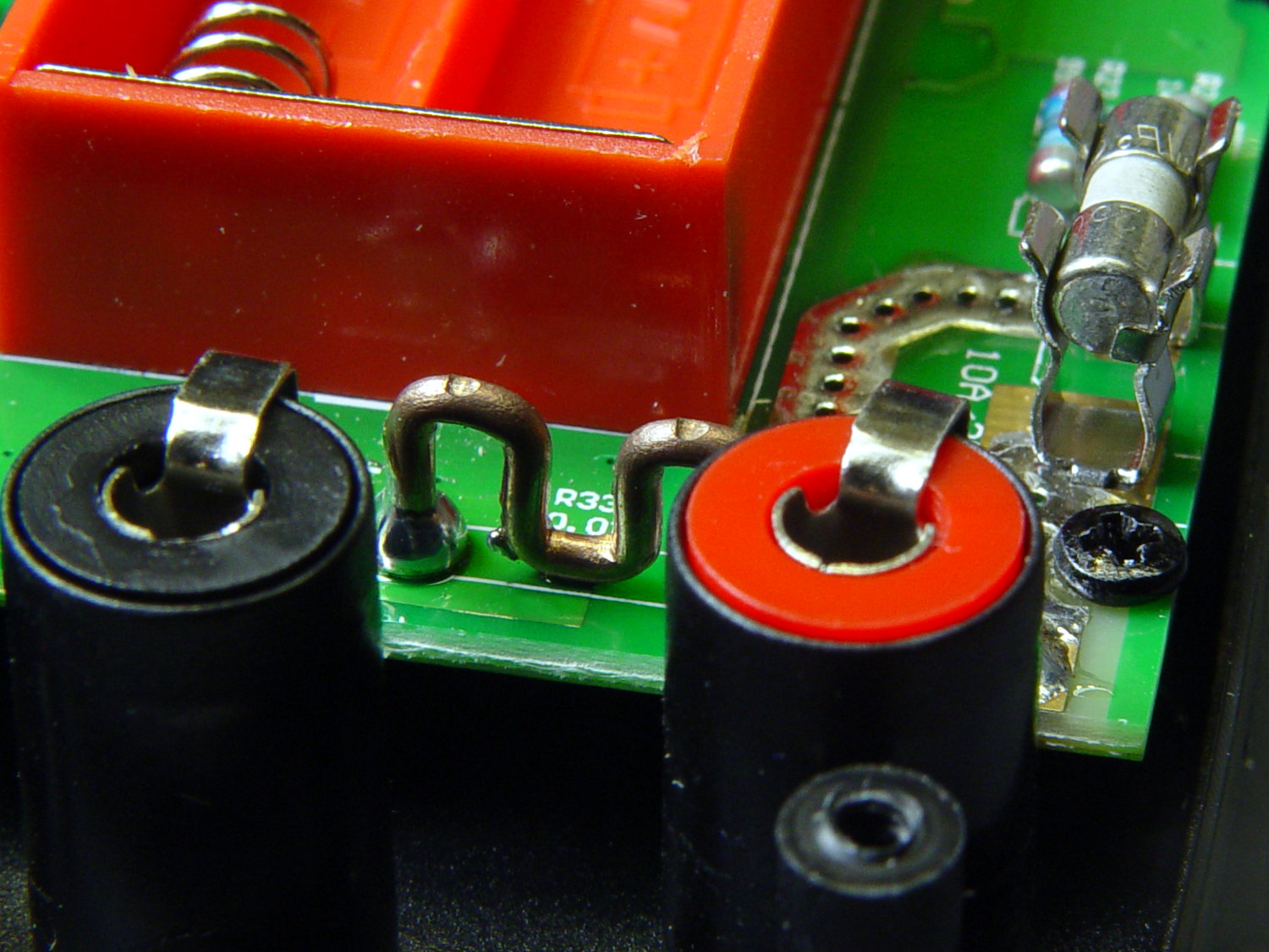
The legend says 0.01R and the conductor doesn’t look quite like pure copper:
AN8009 10 A current shunt – side view
The indentations look like clamp marks from the bending jig, rather than “calibration” notches made while squeezing the wire with diagonal cutters and watching the resistance on another meter.
One might quibble about the overall soldering quality, but one would also be splitting hairs. I doubt the meter leads could withstand 10 A for more than a few seconds, anyhow.
If you buy enough of something, you can buy pretty nearly anything you want, even cheap precision resistors!
Having recently acquired a pair of photo lights and desirous of eliminating some desktop clutter, I decided this ancient incandescent (!) magnifying desk lamp had outlived its usefulness:
Desk Lamp – original magnifiying head
The styrene plastic shell isn’t quite so yellowed in real life, but it’s close.
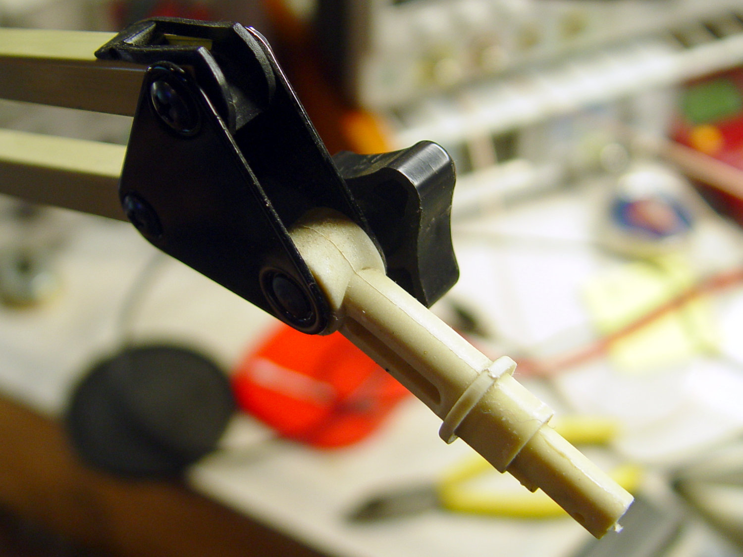
Stripping off the frippery reveals the tilt stem on the arm:
Desk Lamp – OEM mount arm
The photo lights have a tilt-pan mount intended for a camera’s cold (or hot) shoe, so I conjured an adapter from the vasty digital deep:
Photo Light Bracket for Desk Lamp Arm – solid model
Printing with a brim improved platform griptivity:
Photo Light Bracket for Desk Lamp Arm – Slic3r preview
Fortunately, the photo lights aren’t very heavy and shouldn’t apply too much stress to the layers across the joint between the stem and the cold shoe. Enlarging the stem perpendicular to the shoe probably didn’t make much difference, but it was easy enough.
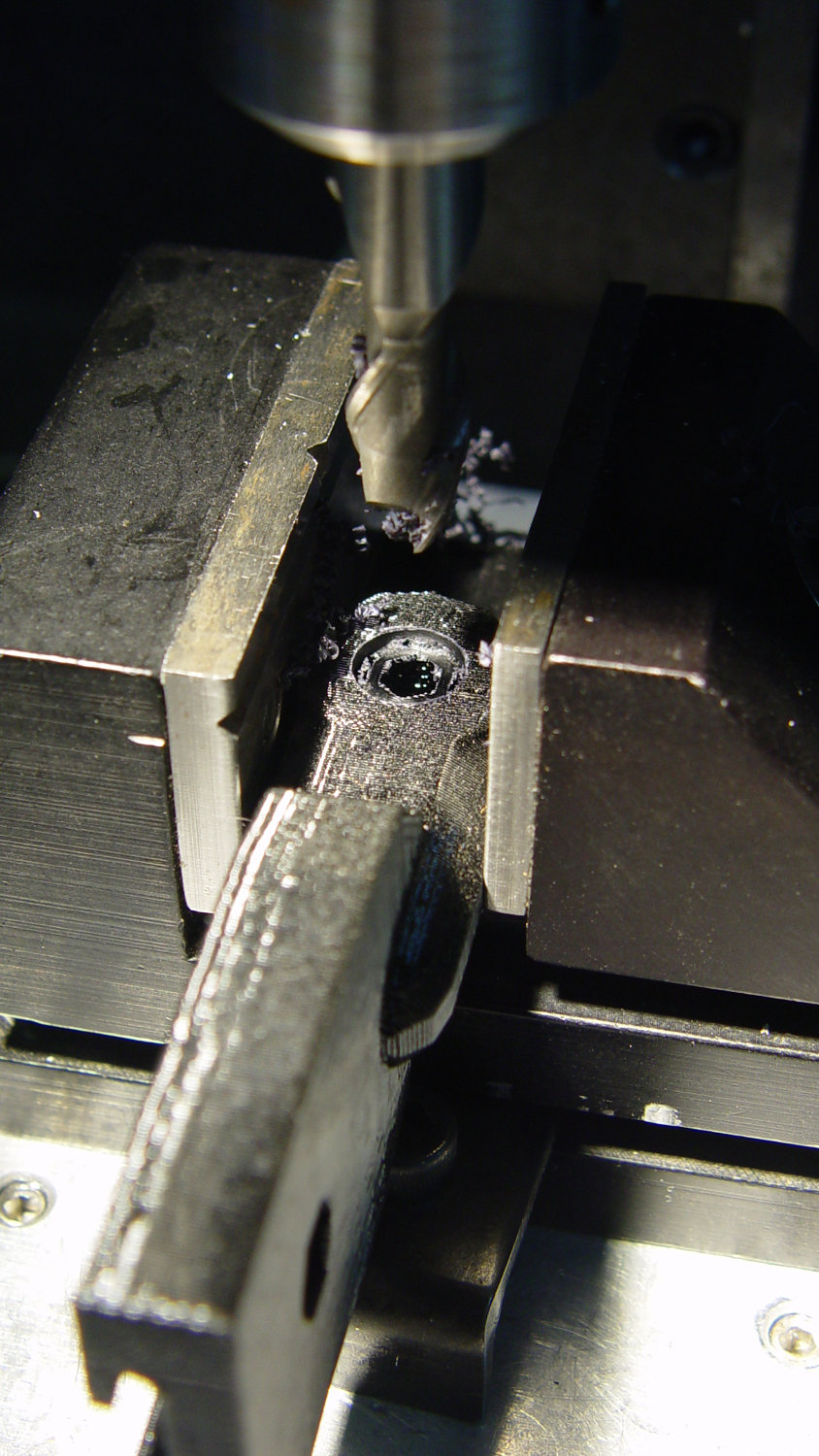
Of course, you (well, I) always forget a detail in the first solid model, so I had to mill recesses around the screw hole to clear the centering bosses in the metal arm plates:
Photo Lamp – bracket recess milling
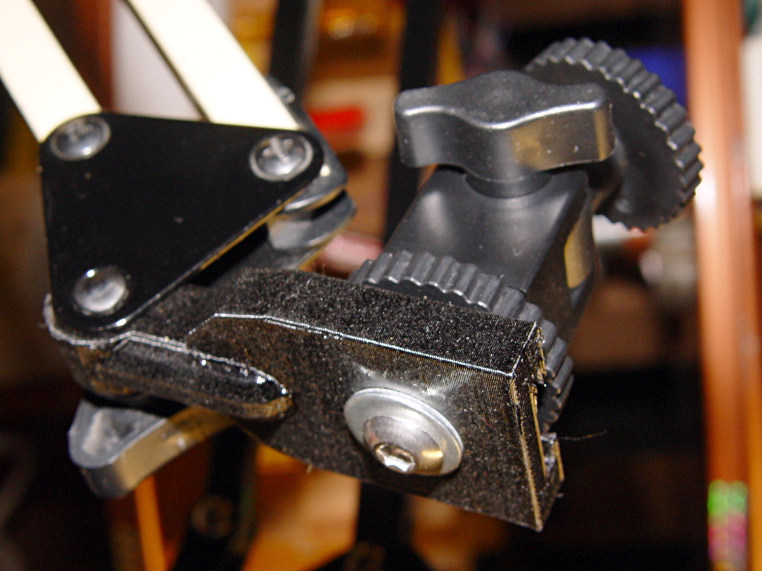
Which let it fit perfectly into the arm:
Desk Lamp – photo lamp mount installed
The grody threads on the upper surface around the end of the slot came from poor bridging across a hexagon, so the new version has a simple and tity flat end. The slot is mostly invisible with the tilt-pan adapter in place, anyway.
There being no need for a quick-disconnect fitting, a 1/4-20 button head screw locks the adapter in place:
Photo Lamp – screw detail
I stripped the line cord from inside the arm struts and zip-tied the photo lamp’s wall wart cable to the outside:
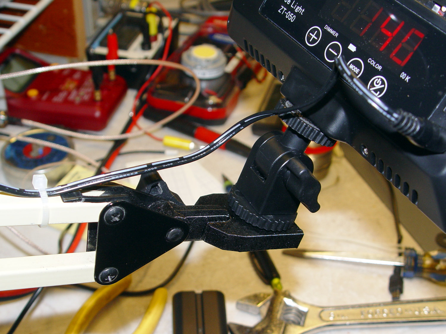
Photo Lamp – installed
And then It Just Works™:
Photo Lamp – test image
The lens and its retaining clips now live in the Big Box o’ Optical parts, where it may come in handy some day.
This file contains hidden or bidirectional Unicode text that may be interpreted or compiled differently than what appears below. To review, open the file in an editor that reveals hidden Unicode characters.
Learn more about bidirectional Unicode characters
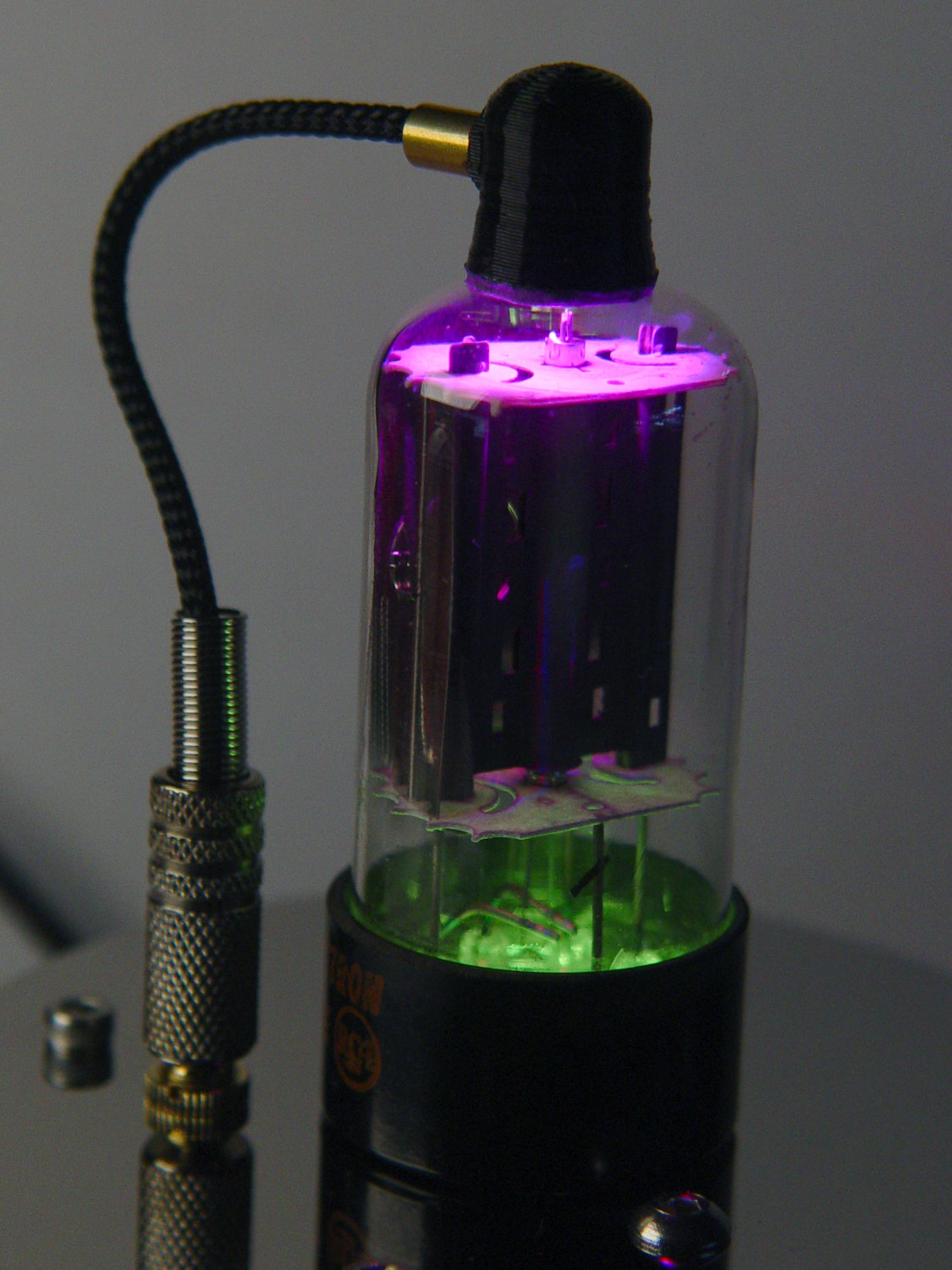
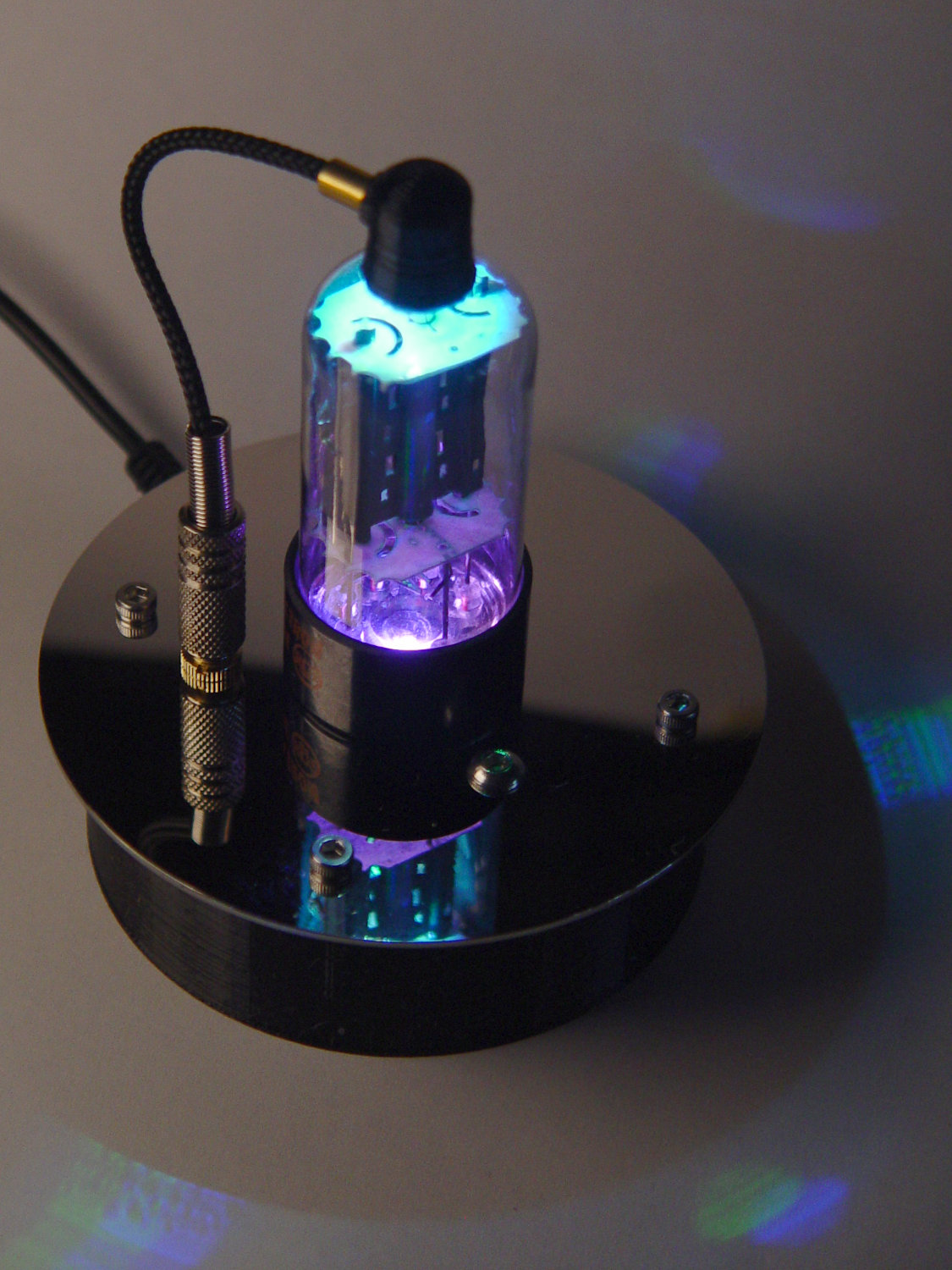
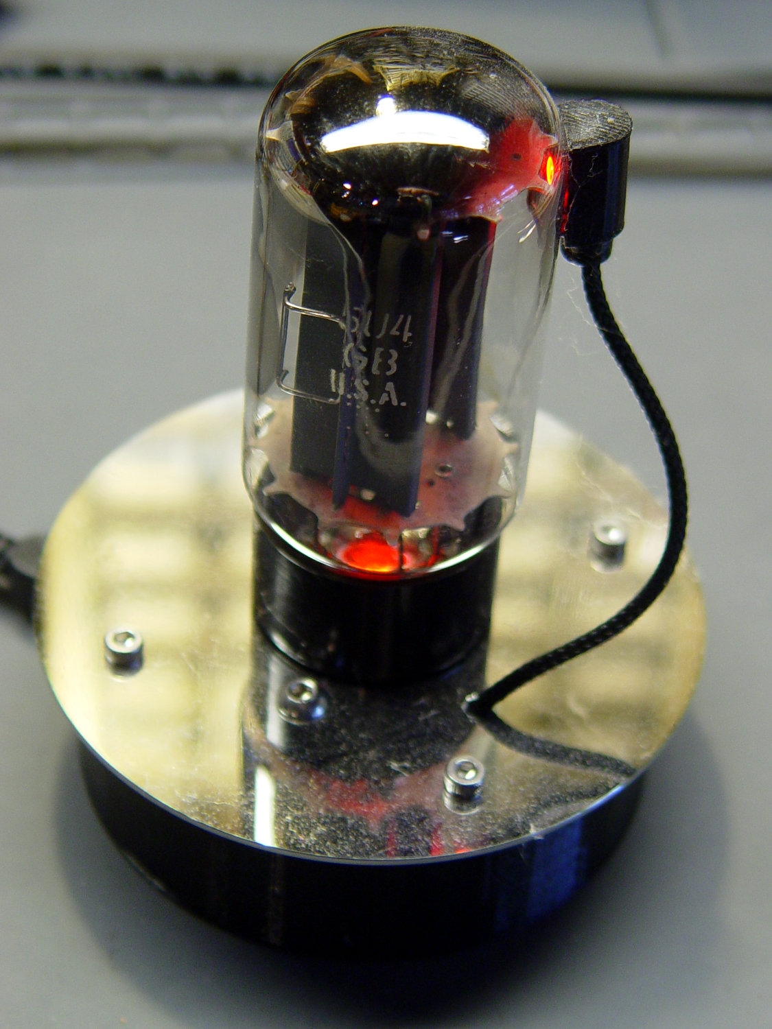
With the wrecked 5U4GB safely in the trash, I popped a smaller, somewhat less stately triode from the Big Box o’ Hollow-State Electronics and wired it up with a pair of SK6812 RGBW LEDs:
Triode – Purple-green phase
The tube’s markings have long since vanished, but, at this late date, all that matters is an intact glass envelope!
After two years, the ordinary white foam tape holding the knockoff Arduino Nano lost most of its sticktivity and easily popped off the 3D printed base:
Triode – Nano PCB – white strips
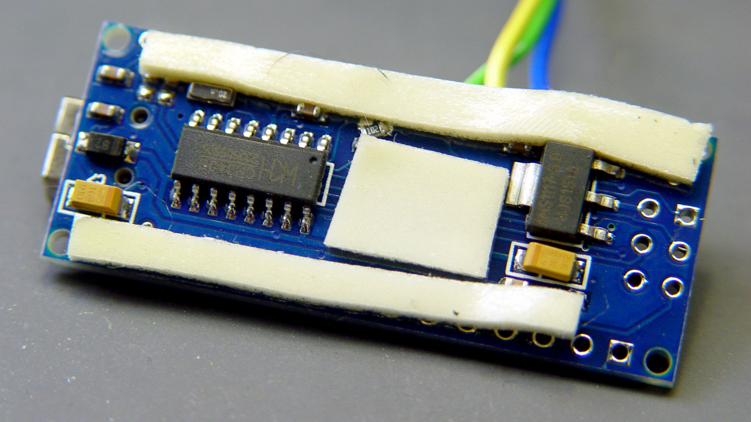
Two layers of 3M outdoor-rated foam tape clear the bottom-side components and, based on current evidence, its stickiness should stick forever more:
Triode – Nano PCB – 3M strips
The alert reader will notice the mis-soldered 1 kΩ SMT resistor above-and-right of the CH340 USB interface chip. I think those two resistors are the isolators between the 328P microcontroller and the CH340, letting you use the TX and RX lines as ordinary I/O without killing either chip.
Despite the mis-soldering, it evidently passed their QC and works fine. Seeing as how I didn’t notice it until just now, it’ll remain in place until I must open the lamp base for some other reason, which may never happen.
The data output is now on pin A5, to match the rest of the glowing widgetry:
Triode – Nano installed
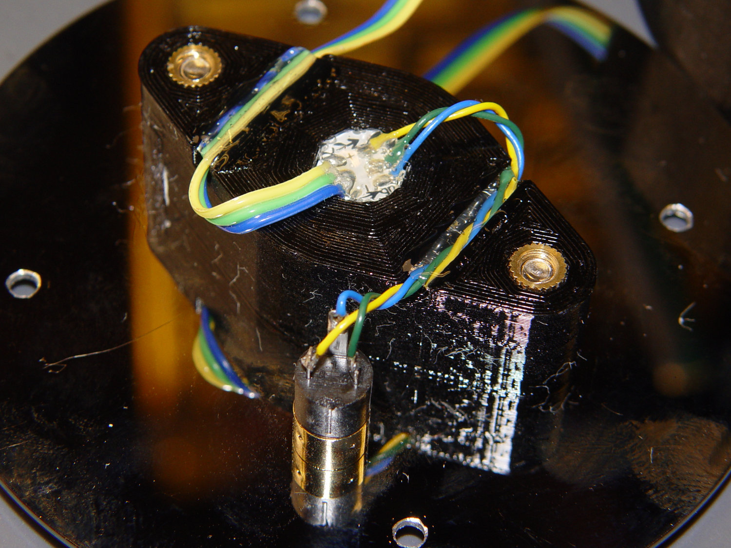
Blobs of hot melt glue affix the SK6812 and wiring to the socket:
Triode – socket wiring
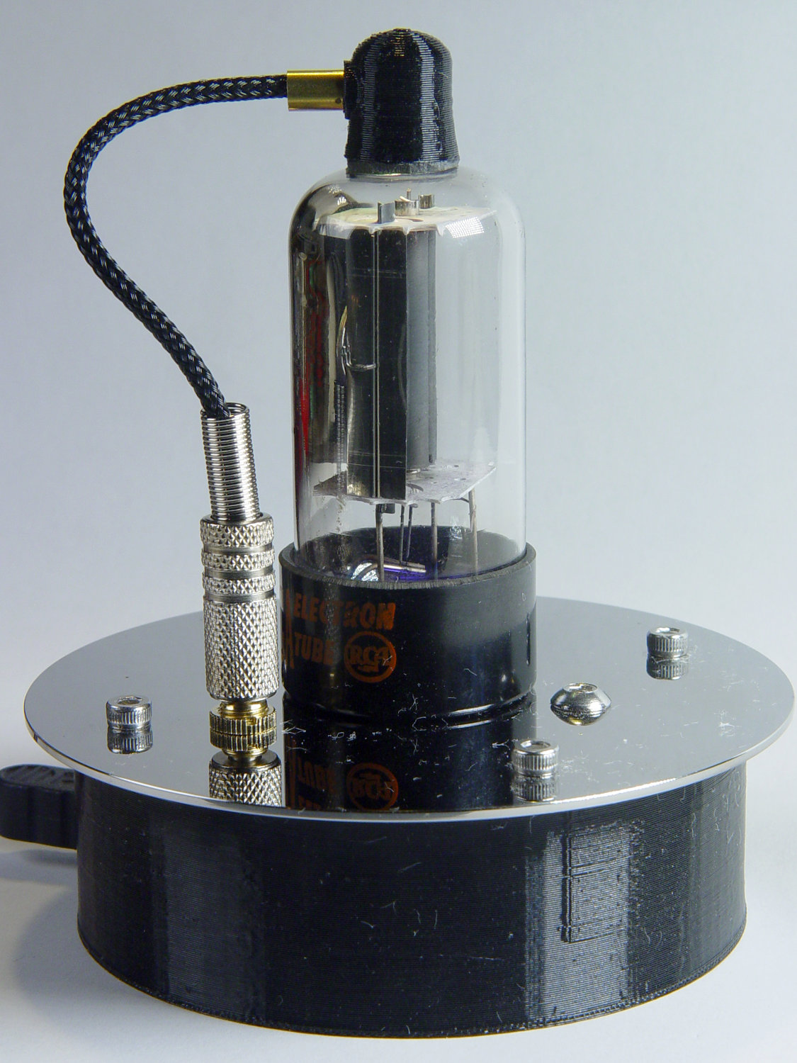
The original “plate cap” wiring ran directly through a hole in the hard drive platter, which I embiggened for a 3.5 mm panel-mount headphone jack. The knurled metal plug looms next to this smaller tube, but it looks better (in a techie sense) than the raw hole:
Triode – plate cap plug
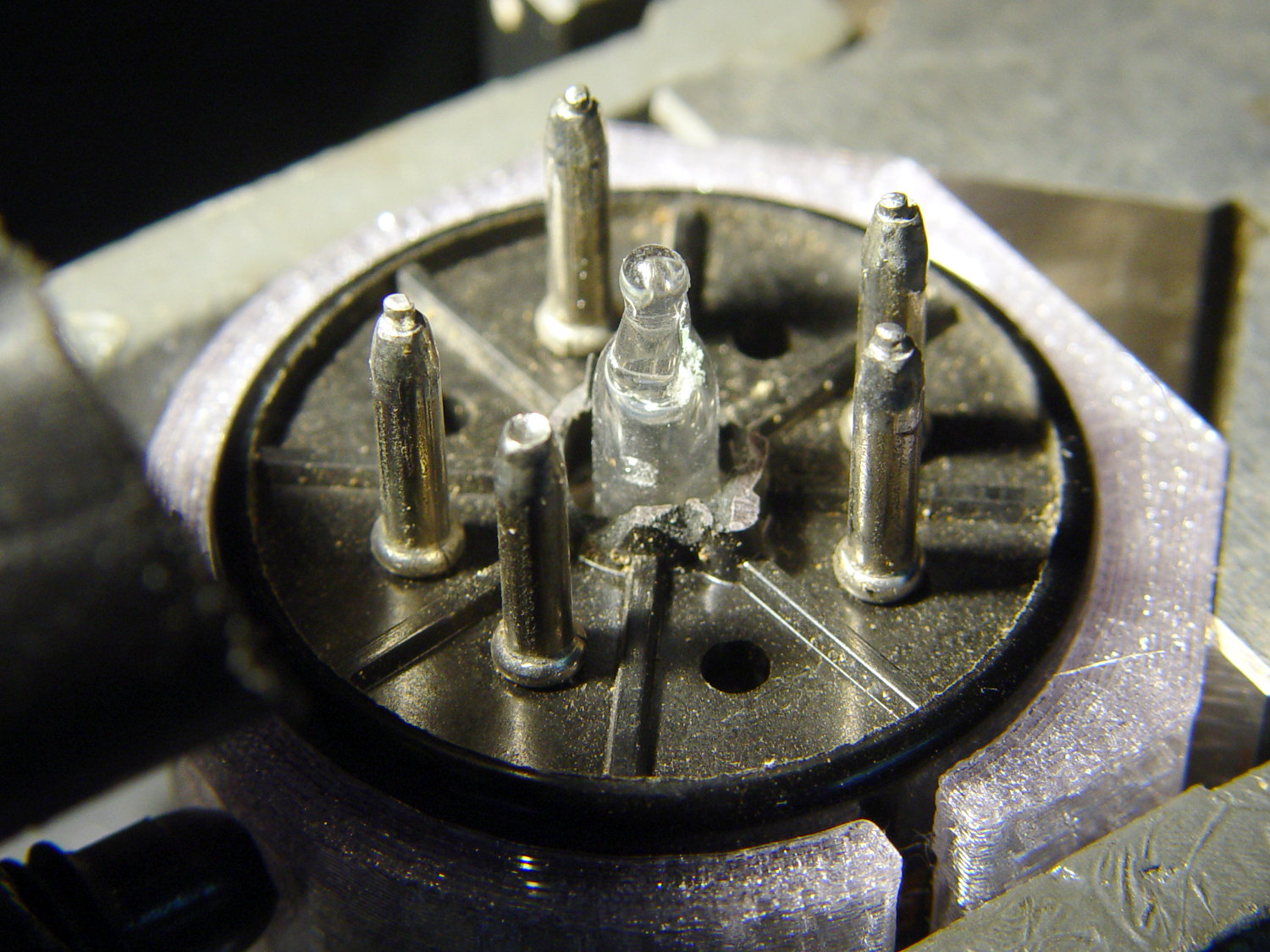
Octal tubes have an opaque Bakelite base, so I devoted some Quality Shop Time™ to the post:
Triode – base tip exposed
Although I’d made a shell drill for 5U4’s base, this base was so crumbly I simply joysticked the spinning cutter around to knock off the rest of the post:
Triode – finished base
The shell drill would open the bottom to admit a bit more light. I may do that to see if it makes any visible difference.
I didn’t expect the serrations in the top mica plate to cast interesting patterns around the platter:
Triode – cyan-purple phase
Memo to Self: use the shell drill to avoid nicking the evacuation tip!
It’s been running more-or-less continuously since late 2016, so call it
Because I’d be crazy to replace it with another likely-to-fail WS2812, I had to remove both of them before installing SK6812 RGBW LEDs and updating the Arduino Nano.
Unfortunately, I did a really good job of bonding the side light to the tube with epoxy:
Failed WS2812 – 5U4GB broken glass
The last tube manufacturing step involved flashing the getter onto the tube envelope, so as to remove the last vestige of air. Admitting air oxidizes the getter:
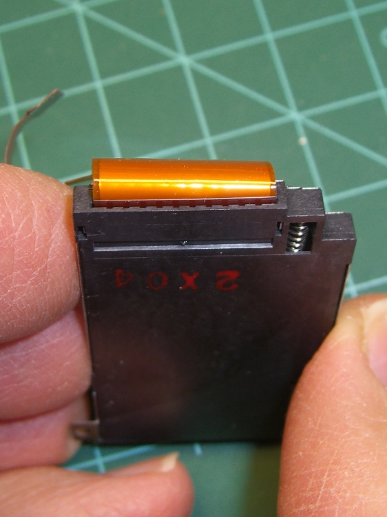
Gently pry the metal cover outward to clear the latches along the sides:
DSC-F717 – Memory Stick socket cover latches
The cover remains held in place by two tabs inside the holes on either side of the Memory Stick contacts, one of which is already free in the previous photo:
DSC-F717 – Memory Stick socket – bottom
The small spring on the left ejects the Memory Stick and will, if suitably provoked, launch itself across the bench. Be prepared!
Use a pointy instrument to ease those tabs away from their latches and pop the top:
DSC-F717 – opened Memory Stick socket
I cleaned the contacts, not that they appeared particularly filthy, gently bent them upward by three micro-smidgens to apply a bit more pressure to the card’s contacts, and reassembled the socket in reverse order.
I put a strip of Kapton tape on the back of the cable termination paddle (shown here during the previous repair) to ensure a snug fit:
DSC-F717 Memory Stick socket – cable entry
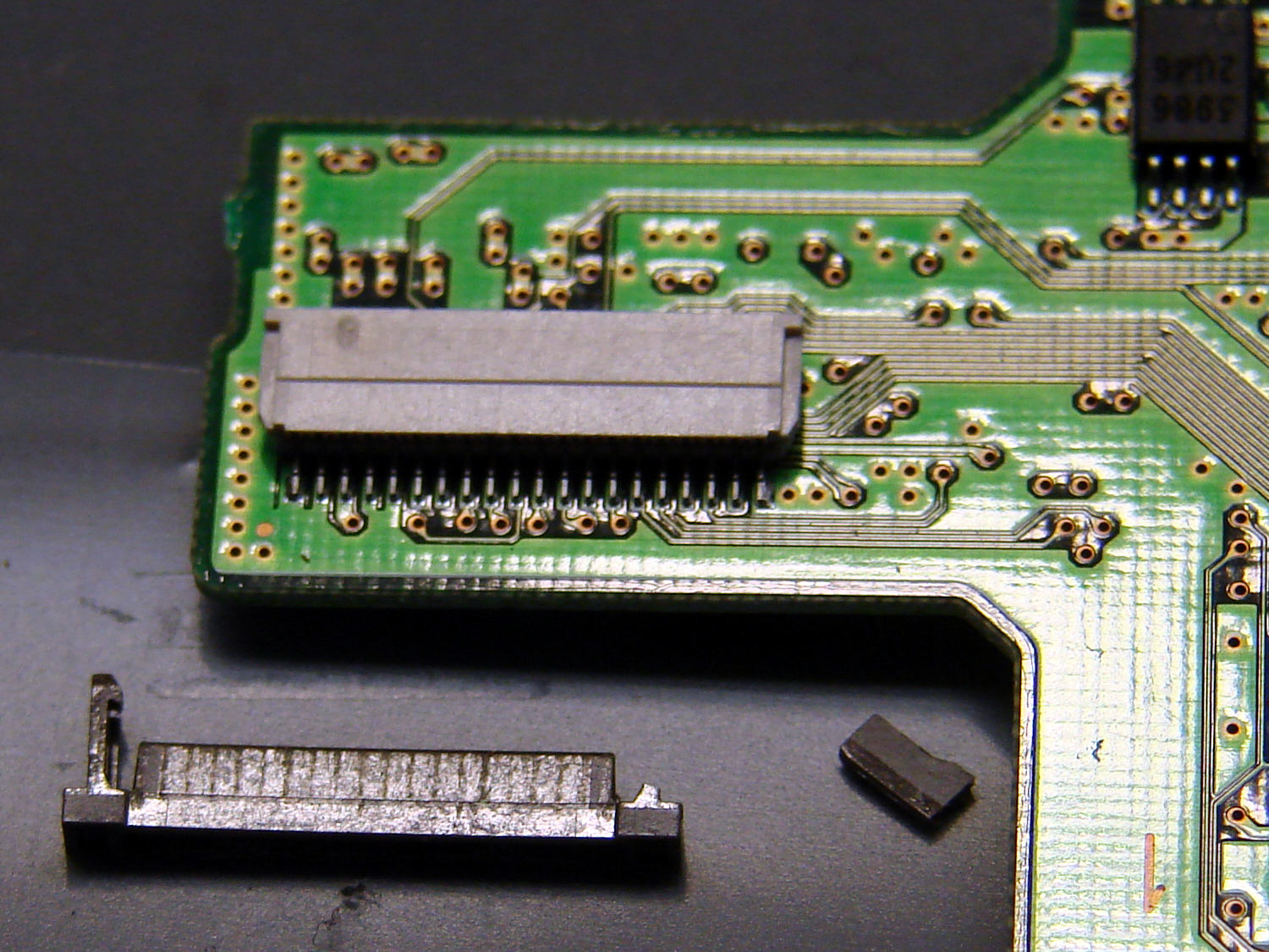
Unfortunately, I snapped off a locking tab on one of the ribbon cable connections to the main board:
DSC-F717 – broken cable clamp
The cable threads through the middle of the clamp, which then slides into the socket and applies pressure to the contacts through the cable: no clamp, no pressure, no good.
For lack of anything smarter, I tamped the clamp into the socket and applied a strip of Kapton tape to maintain everything in more-or-less the right position:
DSC-F717 – tape-anchored cable
Definitely unpretty, but better than nothing. While I was in there, I reinforced the other connections with similar clamps.
Reassemble the camera in reverse order and it’s all good:
DSC-F717 – repaired – first image
It probably won’t last another decade, but ya never know …