The Smell of Molten Projects in the Morning

Ed Nisley's Blog: Shop notes, electronics, firmware, machinery, 3D printing, laser cuttery, and curiosities. Contents: 100% human thinking, 0% AI slop.

Category: Electronics Workbench

Electrical & Electronic gadgets

  • Tektronix AM503: Q230 Dual JFET Replacement

    Tektronix AM503: Q230 Dual JFET Replacement

    Some suggested 151-1032-00 replacements obviously won’t work, such as Tekwiki’s 2N5397 single JFET. Bonding a pair into a single heatsink might suffice, but two separate cans generally aren’t identical enough for the purpose.

    Curiously, Tekwiki also lists the 2N5911 as a 151-1032-00 replacement, which (being an actual dual JFET) looks more promising. This agrees with another cross-reference, although the “Sim[ilar] to” suggests considerable caution.

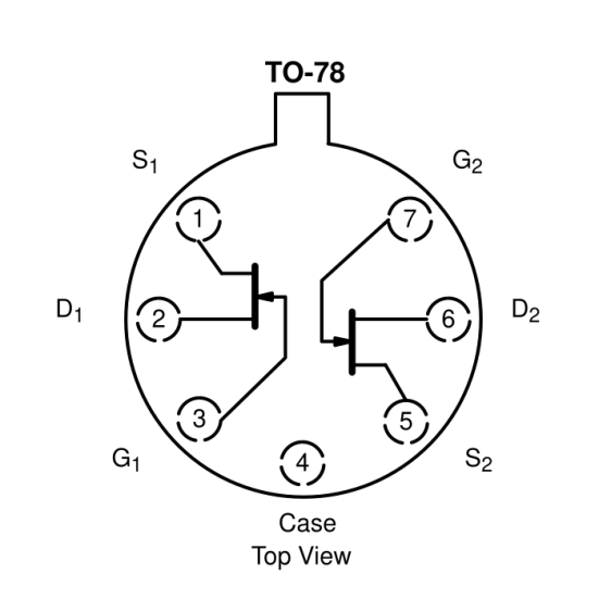
    The 2N5911 pinout, as taken from its datasheet:

    2N5911 Dual JFET pinout
    2N5911 Dual JFET pinout

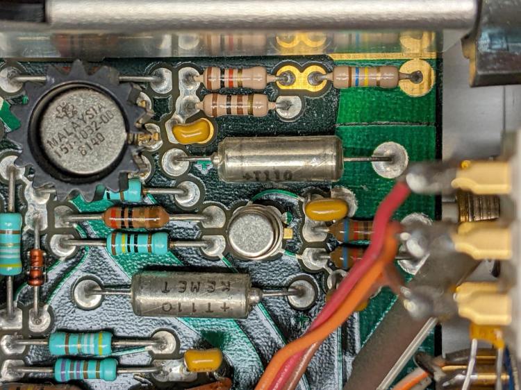
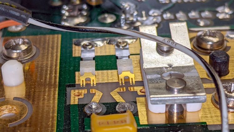
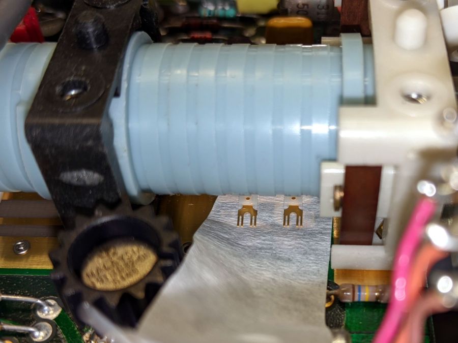
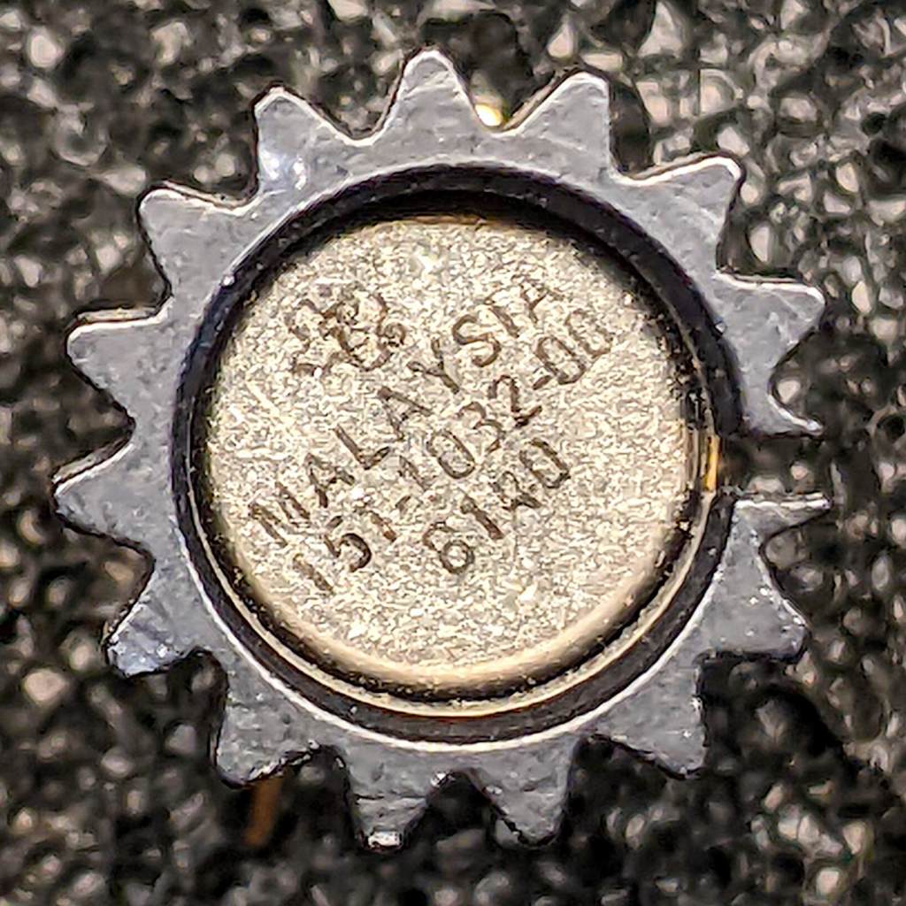
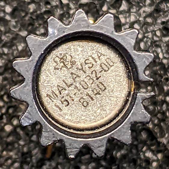
    The actual Tek 151-1032-00 can in its heatsink, oriented with the tab at the top (just visible to the right of the heatsink fin):

    Tek 151-1032-00 - top view
    Tek 151-1032-00 – top view

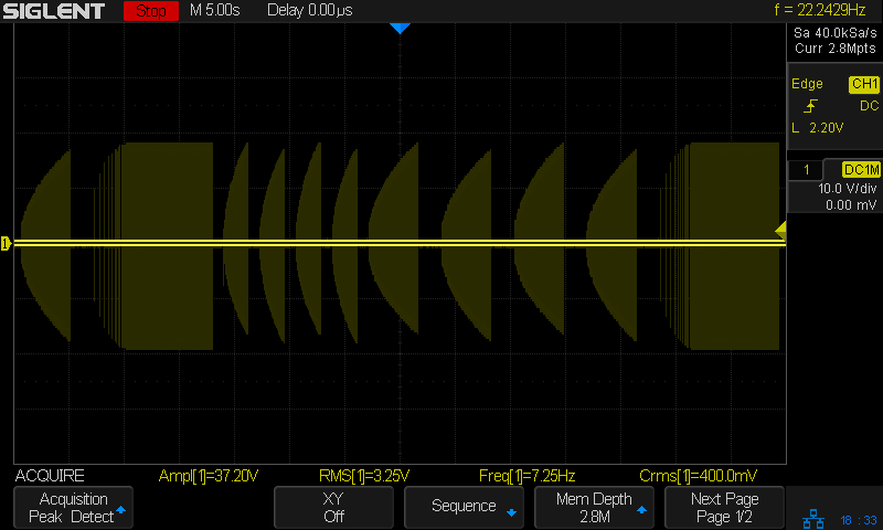
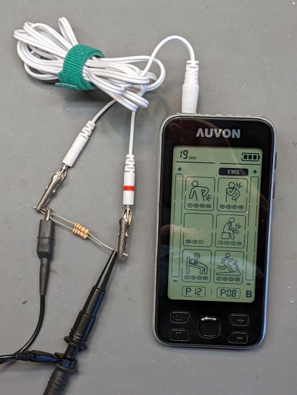
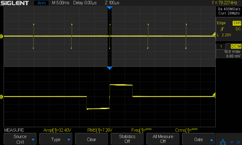
    Testing one side (with the tab on the left):

    Tek 151-1032-00 test side A
    Tek 151-1032-00 test side A

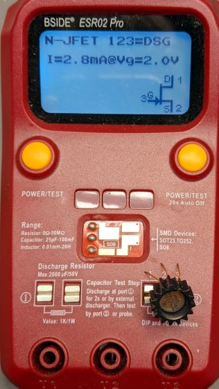
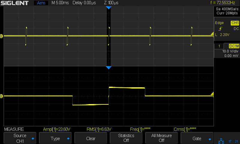
    And the other side (tab still on the left):

    Tek 151-1032-00 test side B
    Tek 151-1032-00 test side B

    A picture being worth a kiloword:

    Tek 151-1032-00 - measured pinout
    Tek 151-1032-00 – measured pinout

    The drain and source over on the left side seem to be swapped compared to the 2N5911, although both gates are on the proper pins. This being a JFET, the source and drain may be electrically identical and it’s possible the tester labelled them backwards. The only way to be sure Tek wasn’t tragically clever is to poke around the PCB to figure out which pins connect to which other components.

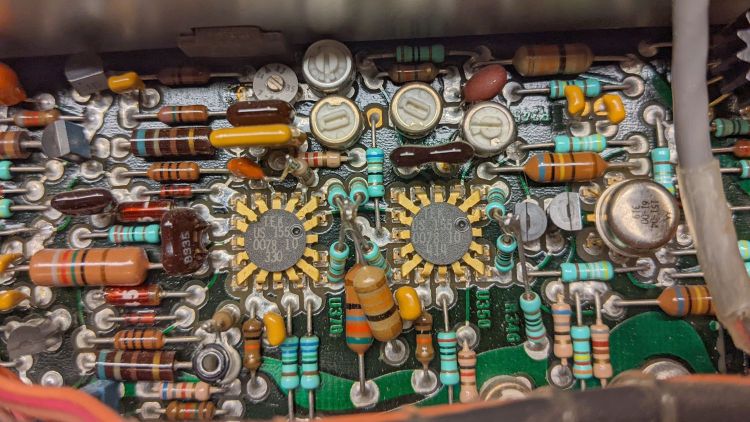
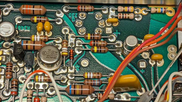
    So take a picture of the component neighborhood around the Q230 sockets:

    PXL_20220105_210538214
    PXL_20220105_210538214

    Overlay it with a similar picture of the solder side, suitably reversed / recolored / transformed to match:

    Tek AM503 - 151-1032-00 area - X-ray traces
    Tek AM503 – 151-1032-00 area – X-ray traces

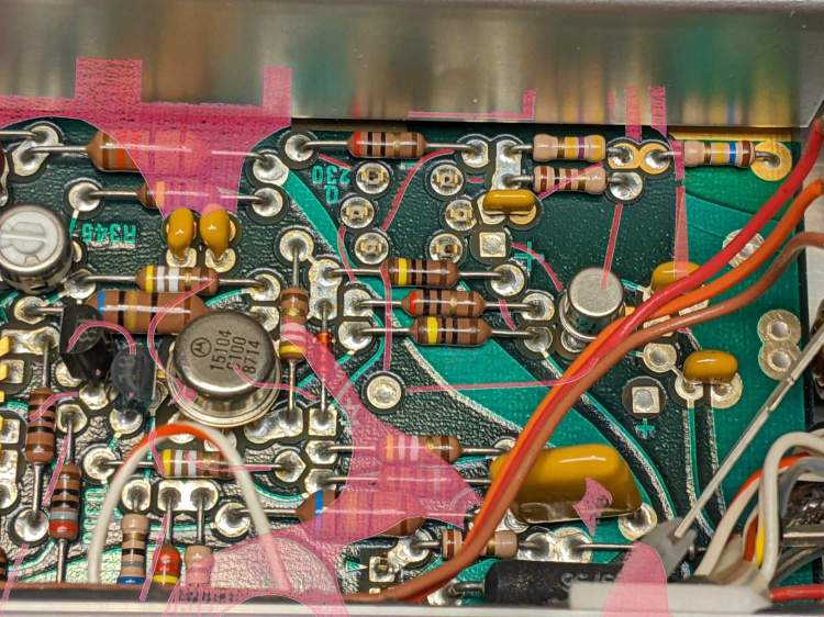
    The copper-side traces aren’t complete, as the red coloring marks only traces under the soldermask and omits bare solder-coated traces. Some traces on the component side run invisibly under parts. If I were doing it for money, not love, I’d pay more attention to the details.

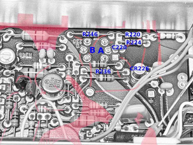
    Devote some time to tracing the traces and labeling the parts:

    Tek AM503 - 151-1032-00 area - part IDs
    Tek AM503 – 151-1032-00 area – part IDs

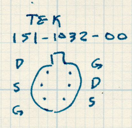
    Then doodle out the actual connections:

    Tek 151-1032-00 - part connections
    Tek 151-1032-00 – part connections

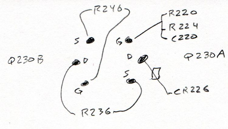
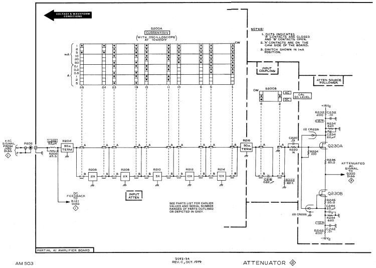
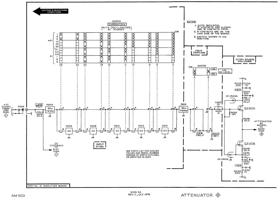
    R246 shows Q230B lives in the left side of the can, because it’s connected between the B gate and B source pins, and confirms the tester swapped the B source and B drain pins. Whew!

    R236 connects the B drain and the A source, confirming the pinout matches the 2N5911.

    Comfortingly, the A side gate goes to all those other parts as it should.

    So a 2N5911 will drop right into the Q230 socket with the proper pins going to the proper places. Whether it’s electrically Close Enough™ to the Tek spec, whatever it might have been, remains to be seen, but a good transistor circuit won’t depend too much on the actual transistor parameters.

  • Tektronix AM503: Noisy Q230 Dual JFET

    Tektronix AM503: Noisy Q230 Dual JFET

    The fact that changing R220 also changed the noise should have pinpointed the noise source, but such things are always more obvious in retrospect than in real time running. This post should help me start the next debugging spree a bit further up the learning curve.

    The AM503 signal path includes a pair of … unique … differential amplifier ICs made by Tektronix back in the early days of integrated circuitry:

    Tek AM503 - U370 U350 detail
    Tek AM503 – U370 U350 detail

    The picture has the signal flowing right-to-left through U350 and U370, starting with the Q310 dual NPN in the metal can and the Q315/325 PNP pair (both over on the right side near the cable).

    The schematic goes left-to-right:

    AM503 - Current Probe Amplifier Schematic - Output Amp - Diag 3
    AM503 – Current Probe Amplifier Schematic – Output Amp – Diag 3

    This AM503 PCB does not have the change that split Q310 into two separate transistors, as shown in the upper left of the schematic.

    The single-ended input signal comes from Q230 at the output of the attenuator on the previous schematic page:

    AM503 - Current Probe Amplifier Schematic - Attenuator - Diag 2
    AM503 – Current Probe Amplifier Schematic – Attenuator – Diag 2

    Here, U350 mashes the signal together with the DC offset control and makes it differential, U370 filters it, then Q390 produces a single-ended signal for the scope output. The architecture makes sense when you realize the AM503 started out as a mainframe oscilloscope plugin and became a TM500 plugin as the result of a mid-flight product pivot; think of it as the hardware version of technical debt.

    Anyhow, the differential output of U370 shows the noise across pins 6 and 8 (yellow and magenta):

    Tek AM503 - diff output U370.6-U370.8
    Tek AM503 – diff output U370.6-U370.8

    Again in retrospect, pins 9 and 5 would have been a better choice.

    The white line is the difference between the two pins and resembled the scope output in the bottom trace well enough to satisfy me.

    The differential input to U350 on pins 16 and 14 also shows a distinct similarity to the output noise:

    Tek AM503 - diff input U350.16-U350.14
    Tek AM503 – diff input U350.16-U350.14

    It’s essentially impossible to snap a scope probe around those IC pins, but merely extraordinarily difficult to securely grab the tails of the pin sockets extending beyond the solder side of the PCB.

    Finally, a look across R317, the emitter resistor between the halves of Q310:

    Tek AM503 - diff input - R317
    Tek AM503 – diff input – R317

    That was enough to finally convince me the problem lay upstream of Q310.

    Ruling out the DC level pot required balancing another AM503 atop this one to plug its cable into the PCB, which showed same output noise.

    Hat tip to Sherlock Holmes:

    “When you have eliminated all which is impossible, then whatever remains, however improbable, must be the truth.”

    https://www.goodreads.com/quotes/1196-when-you-have-eliminated-all-which-is-impossible-then-whatever

    Because Q230 is socketed, I pulled it out and popped it into another AM503, whereupon the noise followed the transistor:

    Tek AM503 - three amps - GND
    Tek AM503 – three amps – GND

    All three AM503 amps are set to GND / DC LEVEL CAL. The cyan trance is the formerly noisy amp (now with a good Q230), the magenta trace is the formerly good amp (now with the bad Q230) , and the green trace is the best of the three AM503 amps (untouched, for well and good reason) in my collection.

    So I must replace a four decade old dual JFET sporting Tek part number 151-1032-00. Such things are available, but in rather grisly as-is condition or as New Old Stock collectibles.

    Perhaps a middle ground would suffice? A couple of those should arrive in a while, but it’s not clear they’re a drop-in replacement.

  • Tektronix AM503: Baseline Offset Digression

    Tektronix AM503: Baseline Offset Digression

    One of my Tek AM503 current probe amplifiers (SN B064098) suffered from DC offsets in the AC / GND / DC modes, to the extent that zeroing the GND (more formally known as “CAL DC LEVEL”) offset wouldn’t keep the other two baselines on the scope screen. Kibitizing with another AM503 owner with a different problem clued me to apply a change made in later units: replace the 1 kΩ resistor at R220 with a 470 kΩ resistor to reduce the source impedance changes between the switch positions:

    AM503 - R220 change
    AM503 – R220 change

    For the record, R220 sits parallel to the attenuator shield above and to the right of Q230 (in the black clip-on heatsink):

    Tek AM503 - R220 detail
    Tek AM503 – R220 detail

    The new resistor somewhat reduced the offset problem, but also dramatically increased the noise level I’d been studiously ignoring, to the point where the AM503 output was unusable:

    Tek AM503 - three amps - GND
    Tek AM503 – three amps – GND

    The rule of thumb is that it’s always a connector or, perhaps, a similar metallic contact in the signal path. The AM503 has a breathtakingly aggressive switched attenuator covering the 94 dB range from 1 mA/div to 50 A/div:

    AM503 - Current Probe Amplifier Schematic - Attenuator - Diag 2
    AM503 – Current Probe Amplifier Schematic – Attenuator – Diag 2

    The switches are cam-driven bifurcated gold-plated spring fingers contacting gold-plated PCB pads under that aluminum shield:

    Tek AM503 - Attenuator Contacts - detail
    Tek AM503 – Attenuator Contacts – detail

    The spring-loaded thing to the right is R206, the first 50 Ω 2× attenuator in the form of thin-film elements fired on a ceramic substrate. The two switches put C218 into the signal path in AC mode.

    You (well, I) clean the fingers by very gently pulling a strip of lens cleaner moistened with isopropyl alcohol through the closed contacts:

    Tek AM503 - Attenuator Contact Cleaning
    Tek AM503 – Attenuator Contact Cleaning

    The pale blue cylinder is the attenuator cam roller extending across the PCB behind the front-panel knob. The two switches bypass C218 in DC mode and connect R220 to ground in GND mode.

    Clean gold-on-gold contacts are about as good as it gets and those things looked absolutely pristine. After wiping the contact connecting R220 to ground had no effect, it finally penetrated my thick skull that the problem wasn’t in the attenuator contacts and had to be downstream in the amplifier and filter chain.

    Reseating all the cable connectors and jostling the (socketed!) semiconductors also had no effect.

    Could one of the semiconductors have gone flaky after four decades?

    More tomorrow. Spoiler: yup.

  • Auvon TENS/EMS: Modulation Waveforms

    Auvon TENS/EMS: Modulation Waveforms

    These scope screen shots use the same test setup as the pulse measurements:

    Auvon AS8016 - test setup
    Auvon AS8016 – test setup

    The sweep speeds run much slower to capture the complete envelope, which can be up to a minute long, with enough left over to show the end of the previous sequence and the start of the next. The Moire patterns come from the scope sampling rate, the display resolution, or changes in the pulse repetition frequency. Blame Siglent for not making the scope’s digital data accessible through the network; screen shots are the best I can do.

    The descriptive headings for each screen shot come from The Auvon AS8016 Fine Manual, a PDF version of which you can get from Auvon’s support staff by asking nicely. I identify the modes as Mxx, rather than their Pxx, for reasons that made sense at the time.

    Patterns 1 through 16 correspond to the TENS (Transcutaneous Electrical Nerve Stimulation) label and are intended for pain relief / suppression; they should not make your muscles twitch.

    P1 – Continuous comfortable tingling.

    Continuous 200 µs pulse at 87 Hz

    Auvon M01 Pulse
    Auvon M01 Pulse

    P2 – Comfortable tingling and pulsing sensation.

    Continuous 100 µs pulse at 48 Hz

    Auvon M02 Mod
    Auvon M02 Mod

    P3 – Comfortable rhythmic tingling.

    Blocks of 300 ms on/200 ms off, with 150 µs pulse at 48 Hz

    Auvon M03 Mod
    Auvon M03 Mod

    P4 – Continuous comfortable tingling.

    Continuous 100 µs pulse at 48 Hz

    Auvon M04 Pulse
    Auvon M04 Pulse

    P5 – Comfortable and slow tingling firstly, then the frequency is significantly increased, and it becomes a noticeable tingling sensation.

    Continuous 250 µs pulses, stepping from 10 to 102 Hz and back down

    Auvon M05 Pulse
    Auvon M05 Pulse

    P6 – Low frequency beating with a slight tingling sensation.

    Continuous 250 µs pulses at 2 Hz

    Auvon M06 Mod
    Auvon M06 Mod

    P7 – Low frequency slight beating firstly and then continuous comfortable tingling.

    Bursts of 150 µs pulses for 3 s separated by isolated 200 µs pulses

    Auvon M07 Mod
    Auvon M07 Mod

    P8 – Low frequency slight beating firstly and then comfortable pulsing sensation.

    Bursts of 150 µs pulses for 3 s separated by isolated 200 µs pulses. Seems identical to P7, although the bursts may be slightly different.

    Auvon M08 Mod
    Auvon M08 Mod

    P9 – Comfortable tingling from shallow to deep with 3-4 seconds pause.

    Auvon M09 Mod
    Auvon M09 Mod

    P10 – Comfortable pulsing sensation from shallow to deep with 3-4 seconds pause.

    Auvon M10 Mod
    Auvon M10 Mod

    P11 – Variable comfortable tingling, slight beating and scrapeing [sic] sensation.

    Auvon M11 Mod
    Auvon M11 Mod

    P12 – Comfortable slight tingling from shallow to deep with 3-4 seconds pause.

    Auvon M12 Mod
    Auvon M12 Mod

    P13 – Comfortable tingling and pulsing sensation from shallow to more deep with 3-4 seconds pause.

    Auvon M13 Mod
    Auvon M13 Mod

    P14 – Rhythmic continuous beating.

    Much higher voltage pulses!

    Auvon M14 Mod
    Auvon M14 Mod

    P15 – Rhythmic scrapeing [sic] sensation.

    Auvon M15 Mod
    Auvon M15 Mod

    P16 – Quick slight beating first, then comfortable tingling.

    Auvon M16 Mod
    Auvon M16 Mod

    Patterns 17 through 24 sport the EMS (Electrical Muscle Stimulation) label and should make your muscles twitch in various ways.

    P17 – Low frequency slight beating.

    Continuous 250 µs pulse with idle time at 4.8 Hz.

    Auvon M17 Pulse
    Auvon M17 Pulse

    P18 – Low frequency beating.

    Continuous 250 µs pulse at 6.8 Hz.

    Auvon M18 Pulse
    Auvon M18 Pulse

    P19 – Beating from low frequency to a little high frequency.

    Auvon M19 Mod
    Auvon M19 Mod

    P20 – Muscle twitches at a very low frequency. It feels like a tapping massage.

    Continuous 250 µs pulse at 13.5 Hz.

    Auvon M20 Pulse
    Auvon M20 Pulse

    P21 – This program activates the muscle in a short tingling cycle. It is smoother than P1/P2.

    Auvon M21 Mod
    Auvon M21 Mod

    P22 – This program gently warms up the muscles prior to exercise; it feels like a rhythmic massage. Increase intensity until you get a strong but comfortable muscle movement.

    Auvon M22 Mod
    Auvon M22 Mod

    P23 – This program uses a pulse frequency appropriate to fast twitching muscle fibers. It improves their anaerobic capacity and is used for improving maximum muscle strength.

    Auvon M23 Mod
    Auvon M23 Mod

    P24 – This program gently warms up the muscles prior to exercise; it feels like a rhythmic beating and comfortable tingling. Increase intensity until you get a strong but comfortable muscle movement.

    Auvon M24 Mod
    Auvon M24 Mod

    Despite the icons on the unit’s display, the manual suggests you can apply pretty nearly any pattern to any muscle, but now we all know what’s coming out of those jacks …

  • Auvon TENS/EMS: Pulse Waveforms

    Auvon TENS/EMS: Pulse Waveforms

    The Auvon AS8016 TENS/EMS unit produces bipolar pulses with no net DC offset, so the UI controls the negative and positive amplitudes equally. The range has 20 steps, with the screen shots here set to 10 units. The actual output voltage depends on the mode, with some modes producing a peak voltage well above the others at the same UI setting.

    It’s worth noting the effect comes from current passed through skin and muscle, rather than voltage applied to it. The test setup uses a 500 Ω resistance to make the current vary linearly with the voltage (which is definitely not the case with human bodies): a 20 V pulse passes 40 mA through the resistor:

    Auvon AS8016 - test setup
    Auvon AS8016 – test setup

    The simplest bipolar pulses always start with the negative phase. The shortest pulse width is 100 µs:

    Auvon M02 Pulse
    Auvon M02 Pulse

    And 150 µs:

    Auvon M03 Pulse
    Auvon M03 Pulse

    And 200 µs:

    Auvon M01 Pulse
    Auvon M01 Pulse

    Up to 250 µs:

    Auvon M06 Pulse
    Auvon M06 Pulse

    Some modes have a short zero-voltage pause between the negative and positive phases:

    Auvon M17 Pulse
    Auvon M17 Pulse

    The pause can be the same duration as the negative and positive phases:

    Auvon M14 Pulse
    Auvon M14 Pulse

    Some modes have pulses starting with the positive phase, others switch the leading phase during the course of the output modulation.

    My casual survey of the consumer-grade field suggests the pulse waveform has less to do with well-tested effects and more to do with marketing or straight-up woo, but I admit to being a cynic.

  • Auvon TENS/EMS: Lead Identification

    Auvon TENS/EMS: Lead Identification

    One of Santa’s myriad helpers recently handed me an Auvon AS8016 TENS/EMS Unit. The manual is, shall we say, light on tech details, but some casual searching turns up the general specs for medical-grade units found in physical therapy offices, plus adjacent Rule 34 compliant (i.e. NSFW) offerings.

    Being that type of guy, I had to look at the electricity. Somewhat to my surprise, the reference load turns out to be a pure 500 Ω resistance, which is easy enough to cobble up from a pair of 1 kΩ resistors:

    Auvon AS8016 - test setup
    Auvon AS8016 – test setup

    The alligator clips crunched around the 2 mm pins are not appropriate for even a brutal e-stim session; they’re from the Small Drawer of Test Connectors, to which they shall return unblooded.

    The red Sharpie highlight around one pin identifies the center conductor of the two-wire cable, as determined by simple continuity testing:

    Auvon AS8016 - marked cable
    Auvon AS8016 – marked cable

    The 22 mil = 0.5 mm wire (from the Little Tin o’ Snippets) fits snugly into the coaxial connector’s center contact; one could probably slip a rounded shim between the shell and the outer contact, perhaps to debug an intermittent connection. Note that the connectors on both ends of the wires are not standardized among various TENS/EMS manufacturers.

    The AS8016 has two pairs of connectors:

    Auvon AS8016 - wire jacks
    Auvon AS8016 – wire jacks

    The A1 and A2 jacks are wired in parallel, as are the B1 and B2 jacks, with the A pair galvanically isolated from the B pair. You can set the modes / programs / pulse parameters differently for A and B. Although the manual doesn’t mention it, using the A and B channels (perhaps with the same settings) prevents a galvanic connection (and thus any current) from flowing between the A and B electrodes; this seems important for electrode pairs placed on opposite sides of your body to prevent current through your heart.

    The pulses have no DC component, so the actual wire polarity doesn’t really matter, but a foolish consistency definitely simplifies going back to re-measure things. Subsequent waveforms show the voltage with respect to the unmarked (outer) conductor.

    Suppressing the DC bias prevents ionic migration between / under the electrode pads. The classic RC-equivalent output circuit uses a series capacitor, resulting in an asymmetric pulse waveform with zero net DC voltage:

    Capacitor Coupled Pulse
    Capacitor Coupled Pulse

    There’s no DC path between the center and outer conductors, but in this day and age the circuitry could be a completely isolated bipolar FET driver:

    Auvon M01 Pulse
    Auvon M01 Pulse

    With all that sorted out, I can make measurements!

  • Christmas Bonus

    Christmas Bonus

    An email arrived yesterday:

    Subject: [redacted] review blog invitation about bluetooth programmer

    Message: Hi dear,

    Thanks for taking time to read this email.

    I am Colleen from [redacted] brand, we sell two way radio on Amazon. I learned that you have wrote two way radio review blog before and I think your blog was written well.

    Now we have a product named bluetooth programmer that need to be reviewed. […] We would like to invite you to write a review blog about it.

    Your can earn $2 from each product sold! We promise it. Just put the link we provided you in your blog and the Amazon backstage will count the data. And we will pay you $2 for per product sold by your link through PayPal on the 30th of every month. (Please provide your PayPal account)

    If you are willing to help us write a blog, please tell us if you have a radio and your address we will send you the product for free to review.

    You can view more detailed information through this link:

    [redacted]

    Perhaps this “review” caught their eye:

    Baofeng UV-5RE radio - overview
    Baofeng UV-5RE radio – overview

    Or maybe it was my opinion of the Baofeng intermod problem?

    Most likely, it’s just the result of an ordinary web search.

    You might think everybody would know about Amazon’s crackdown on out-of-band review kickback scams, but either word hasn’t gotten around or the rewards still exceed the penalties. I think the latter applies, particularly when the offender (or its parent company) can spin up another randomly named Amazon seller with no loss of continuity.

    “Earning” two bucks on a few purchases during the course of a year won’t move my Quality of Life needle, so I reported them to Amazon and that might be that.

    For future reference, the chat with Amazon’s Customer Support rep produced a deep-ish link to their otherwise un-discoverable “Report Something Suspicious” page; the randomly named nodeld is a nice touch.

    Speaking of randomly named sellers, it’s highly likely any Brand Name you remember from the Good Old Days has been disconnected from the tool / hardware / service you remember. Perusing a snapshot of the who-owns-who tool landscape as of a few years ago may be edifying: I didn’t know Fluke and Tektronix now have the same corporate parent.

    Enjoy unwrapping your presents and playing with your toys …