Having put the Tek AM503 with the 4 MHz oscillation (B075593) on the shelf pending arrival of what might be the world’s last remaining NOS 2625 op amp in the “screened and tested” 156-0317-03 grade, I figured I might as well go through the adjustment procedure on one of the bench units (B064098) to reset the gain and reduce the peaky leading edges (green trace):

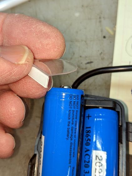
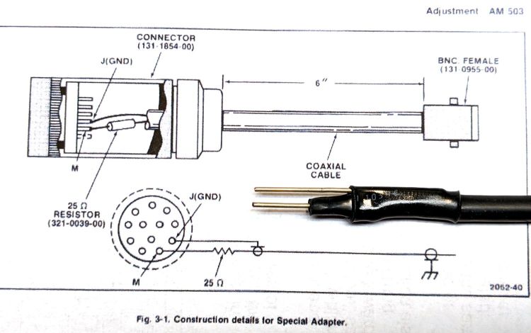
I conjured a low-budget Special Adapter to feed signals into the front-panel connector:
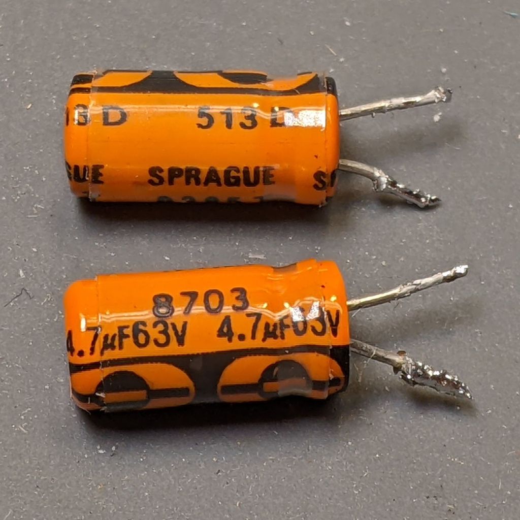
I also used a somewhat smaller resistor in place of the required 3 Ω 3 W wire-wound unit:

It need only soak up a few seconds of the degaussing signal and never even got warm, so it’s all good.
To my surprise, the square-wave output of the JDS6600 Function Generator meets the 10 ns risetime requirement:

Perhaps half an hour of adapter shuffling and trimmer twiddling later, the AM503 output looked better:

The (purple) input comes from the function generator output through a BNC tee and an unterminated foot of coax, so the leading edge ringing is perfectly normal.
With the scope input now providing the 50 Ω termination and the Hall probe clamped around one wire of a clip-to-clip pair of BNC-to-alligator-clip adapters, we’re still not talking RF-grade interconnection quality:

Even through it’s not factory spec, the output tracks the input well enough for my simple needs.
Good old Tek instruments: gotta love ’em!