The Smell of Molten Projects in the Morning

Ed Nisley's Blog: Shop notes, electronics, firmware, machinery, 3D printing, laser cuttery, and curiosities. Contents: 100% human thinking, 0% AI slop.

Category: Electronics Workbench

Electrical & Electronic gadgets

  • Ampeg B-12-XY: Echo Circuit

    Mad Phil asked me to fix up his trusty Ampeg B-12-XY (*) bass guitar amp, having recently fired it up and discovered that the power output tube plates glowed red-hot. I’d planned to replace the electrolytic caps, but Eks, who does this sort of thing all the time, suggested that leaky interstage coupling caps can also cause that problem; the leakage wrecks the phase splitter bias and thus kills the drivers.

    While poking around in the amp I found that the Echo hardware circuitry doesn’t match the schematic for either the B-12-X or B-12-XY. Mad Phil says that’s probably because he had the factory upgrade his original B-12-X to a B-12-XY for the munificent sum of $25, back in the day. It’s unlikely you’ll ever need this, but here’s what I found:

    Ampeg B-12-XY - as-found Echo circuit
    Ampeg B-12-XY – as-found Echo circuit

    The topology resembles the -XY schematic, but with different tube sections and part values.

    The Echo unit over there on the left consists of two springs with magnetic transducers on each end, evidently made by the Hammond Organ folks, who should know something about reverb. This is the bottom view, with the unit attached to the board that supports the amp chassis:

    Ampeg Spring Echo Unit
    Ampeg Spring Echo Unit

    The input transducer, just in case you forget to label the ends before you take it apart:

    Ampeg Spring Echo - input end
    Ampeg Spring Echo – input end

    And the output transducer:

    Ampeg Spring Echo - output end
    Ampeg Spring Echo – output end

    Getting the thing off the speaker box posed a bit of a problem. Remove the four big screws holding the chassis to the board, tilt it carefully forward, hold it in place while you remove the six nuts-and-washers from the vibration isolators, then transport the whole disjointed affair to the workbench. Turns out you (well, I) can’t get the RCA plugs out of the Echo unit’s sockets from the top of the board, but the unit’s mounting screws are on the bottom of the board, where you can’t get to them before you remove the board. Of course, the cables leading to the aforementioned RCA plugs tether the chassis to the Echo unit with pretty nearly no slack at all.

    With everything apart, I rounded the ends of the RCA plug cutouts enough to get them out from the top the next time around, with the board screwed in place atop the speaker box:

    Ampeg Spring Echo unit - top view
    Ampeg Spring Echo unit – top view

    After putting the whole thing together with new caps, the Echo circuit didn’t work. I had cleaned the contacts and connectors, but Eks showed me how it’s really done. Apart from the rotted caps, all the other problems came from minor corrosion in switches, connectors, and tube sockets. Now I know better.

    * Yes, the model numbers really end in X and XY.

  • MGE Ellipse 1200 Battery Arrangement

    The SLA batteries in the MGE Ellipse 1200 UPS finally gave out. This picture shows how they’re arranged inside the box:

    MGE Ellipse 1200 UPS - battery arrangement
    MGE Ellipse 1200 UPS – battery arrangement

    They’re 12 V 5 Ah batteries that are about 12 mm thinner than the garden variety 7 Ah batteries you can get everywhere; they’re not the same size as the generic 5 Ah batteries you might think would work. Of course, there’s not enough room inside the stylin’ case for the larger ones, either. I’m thinking of using fatter batteries anyway and putting a belly band around the gap. Maybe an external battery box with a chunky cable burrowing through a hole in the UPS case?

    For what it’s worth, APC absorbed MGE a while ago (so the MGE website redirects to APC), got Borged by Schneider, then spat out MGE’s consumer grade UPS units to Eaton. You won’t find any of that documented anywhere, but here’s the response from APC after I didn’t find this UPS on their list:

    I do apologize; when APC was acquired by Schneider Electric, the single phase UPS line that MGE once offered was sold to Eaton. Eaton now provides support for the MGE single-phase products. We do not sell batteries for these models. You will actually need to contact Eaton for further assistance regarding the MGE Ellipse units. You may click on the link below to go to Eaton’s website:

    http://powerquality.eaton.com/Default.asp

    The Eaton website does have a battery replacement for this one, but sporting the dreaded “Contact us for price” notation. Given that I got the UPS cheap-after-rebate, I’m thinking maybe this isn’t worth the effort.

  • Stepper Motor Back EMF

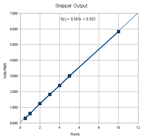
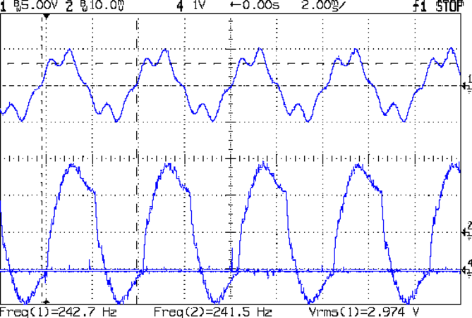
    Some simple measurements using that Pololu driver in its default mixed decay mode and that Arduino sync generator. The captions give the operating conditions; basically, I’m varying the rotation speed by cranking the signal generator driving the Pololu board.

    At 1 rev/s, it’s about as good as it gets:

    Back EMF - 9V 400mA 1 RPS
    Back EMF – 9V 400mA 1 RPS

    At 5 rev/s, the driver has trouble getting current out of the winding:

    Back EMF - 9V 400mA 5 RPS
    Back EMF – 9V 400mA 5 RPS

    At 10 rev/s, things are getting ugly:

    Back EMF - 9V 400mA 10 RPS
    Back EMF – 9V 400mA 10 RPS

    At 20 rev/s, the back EMF has pretty much taken control of the current and the driver is going along for the ride:

    Back EMF - 9V 400mA 20 RPS
    Back EMF – 9V 400mA 20 RPS

    At 25 rev/s, the driver produces only occasional dents in the waveform:

    Back EMF - 9V 400mA 25 RPS
    Back EMF – 9V 400mA 25 RPS

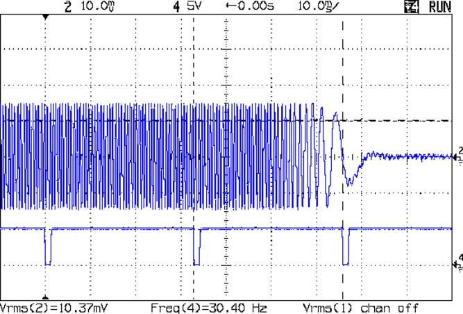
    At 25.3 rev/s, the motor stalled. Even with no back EMF (what with the rotor being stopped and buzzing in frustration), the driver can’t force the current to behave:

    Back EMF - 9V 400mA 25.3 RPS
    Back EMF – 9V 400mA 25.3 RPS

    I don’t have any way to measure the motor’s output torque, but at 1500 RPM there won’t be any worth mentioning.

    For what it’s worth, 25 rev/s means the driver is handling 40 k steps/sec = 25 µs/step. The motors in a Thing-O-Matic run at 3 rev/s to move the XY stages at 100 mm/s, so scale what you see here accordingly.

  • Beard Trimmer: NiCd Rejuvenation

    Strictly speaking, I do not have a beard: I simply do not shave (*). There being no money in selling Trimmers for the Non-shaving, a while back I bought a battery operated Beard Trimmer. The NiCd cells lasted for the predictable few years and recently gave up the ghost entirely: an overnight charged produced a weak buzz with no cutting action to speak of.

    The case uses one-time snap-together latches, which makes dismantling it a challenge. Start by removing all the gimcrackery on the business end, then pry out the two latches holding the it-was-white-once cutting length adjustment ring.  With that out of the way, undo the two latches inside the top and work your way down, prying the case halves apart in the way the overlap flange doesn’t like, so as to force the latches loose.

    This picture shows the six latches, three on each side. The ones just to the right of the blue impeller require the most cursing:

    Beard trimmer case and innards
    Beard trimmer case and innards

    The circuit board snaps out, with the two PCB contact areas clamped down by springy contacts leading to the motor.

    Beard trimmer - battery charger PCB
    Beard trimmer – battery charger PCB

    The two NiCd cells boast of their High Energy, but they’re only 600 mAh. That’s actually too much for this high-drain, short-run application, as they don’t completely discharge. They’re held in place on the right end with a blob of hot melt glue:

    Beard trimmer - NiCd cells
    Beard trimmer – NiCd cells

    I unsoldered the cells and gave ’em a brute-force overnight charge at C/10 = 60 mA, then ran a discharge test (clicky for more dots):

    Beard Trimmer - NiCd Discharge Test
    Beard Trimmer – NiCd Discharge Test

    Lookee that! The cells still deliver their rated capacity, even though they no longer worked with the stock charger. I repeated the slow-charge and discharge trick, which produced a perfectly overlapping trace.

    Flushed with success, I unleashed the built-in charger overnight, then produced a third overlapping trace.

    So they suffered from voltage depression, most likely due to never being completely discharged and then being overcharged far too often. That’s cured by a complete discharge and recharge, which worked perfectly.

    I hack back the overgrowth when it gets bushy and recharge the trimmer when it seems to be getting weak, which used to take a week or two. That’s a bad way to maintain a NiCd battery, particularly as the PCB applies a very low load to keep its computronium running, but I have better things to do than babysit a beard trimmer. Honest.

    Anyhow, assembly is in the reverse order and it’s perfectly happy again.

    I probably won’t change my evil ways, so the next time I’m sure the battery will be really and truly dead.

    (*)  Not shaving adds about ten minutes a day to my life, which I regard as a fair tradeoff over the course of several decades. It also added a decade to my apparent age, Back In The Day when that mattered. Now it seems to knock off a decade, which isn’t entirely a Bad Thing.

  • Arduino Case

    The base of that case makes a good protector to keep an Arduino board out of the conductive clutter on a typical electronics bench. I stopped the printer shortly after it finished the bosses atop the mounting posts:

    Arduino case - base on build platform
    Arduino case – base on build platform

    That yellow filament means I can’t lose it!

  • Casio EX-Z850 Camera Button Failure

    The Casio EX-Z850 camera living in my pocket finally developed a problem. Two buttons on the back select the Review and Camera modes; the former stopped working, which means I can’t see pictures after I take them. The Camera button may still work, but because I can’t display pix, that’s pretty much moot.

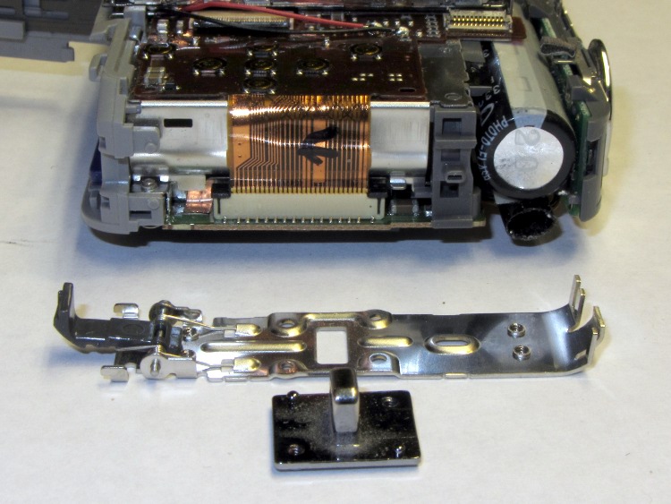
    Taking the camera apart require a Philips 00 screwdriver bit and some care, but eventually you’re confronted with this:

    Casio EX-Z850 camera - opened
    Casio EX-Z850 camera – opened

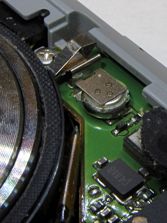
    The buttons and the mode selector dial all connect to the same flexible PCB substrate, which ends up in this connector. You should ease the black pressure bar (seen edge-on here) upward to release the flex PCB:

    Casio EX-Z850 button connector
    Casio EX-Z850 button connector

    As it turns out, the two buttons have a common contact that’s the second trace from the top in the flat cable. Both buttons have good snap action, good conductivity, and seem to work fine. That puts the problem deeper inside the camera, where I don’t see much point in going; I can certainly make things much worse and likely not make them any better.

    In fact, it turns out that the two buttons on the USB/charging cradle don’t work now, either, which implies that the camera buttons run in parallel with those. So there’s something blown in the camera’s guts, which is definitely Bad News.

    Back in the Bad Old Days, you used to take a picture and wait a week or two to get the results back from the drug store. Perhaps it’s fashionably retro to have a digital camera without a Review mode?

  • Stepper Motor Winding Current Rise Time

    Here’s how the stepper drive voltage affects the current rise, using that kludge to sync the scope on one of those motors with L=2.6 mH and R=2.2 Ω. The peak winding current is 1 A, so the first step current-limits at 200 mA.

    At 9 V:

    Current Rise - 9 V 1A 3 RPS
    Current Rise – 9 V 1A 3 RPS

    At 18 V:

    Current Rise - 18 V 1A 3 RPS
    Current Rise – 18 V 1A 3 RPS

    Knowing the rise time and current change, you can calculate the actual voltage across the inductor using:

    VL = L di/dt

    With 9 V drive the motor sees:

    4.4 V = 2.6 mH x 220 mA / 130 us

    With 18 V drive the motor sees:

    14 V = 2.6 mH x 240 mA / 45 us

    So, in round numbers, the driver MOSFETs, winding resistance, and all the crappy solderless breadboard connections soak up about 4 V of the available supply voltage. There’s some back EMF in there, too, but I haven’t measured that part of the puzzle yet.

    The motor is turning at 3 rev/s in 1/8 microstepping mode, so each microstep is:

    200 us = 1/(3 rev/s x 1600 step/rev)