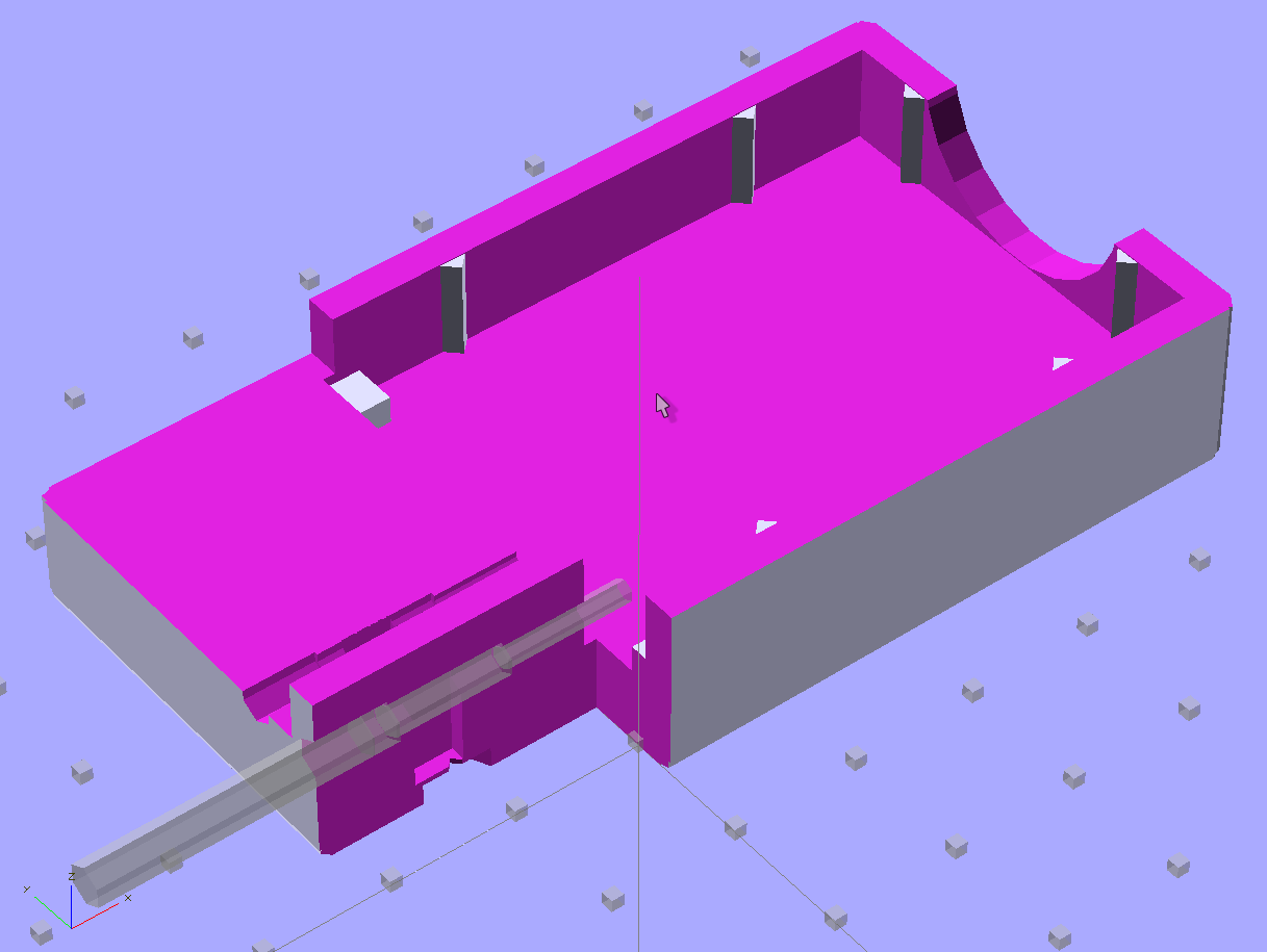
Having twice failed to make music-wire springs work, I rummaged around in the Big Box o’ Small Springs with more diligence and unearthed a pair of coil compression springs that exactly match the pin ferrule OD. Twiddling the solid model produced this longer & flatter version with in-line springs and cylindrical plugs holding them in place:
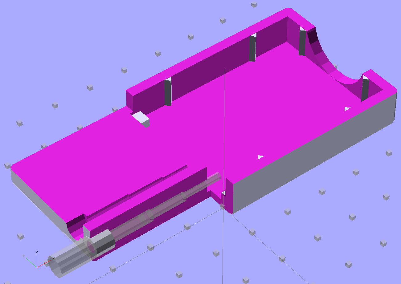
A closeup of the pin arrangement, which now looks very clean and easy to build:

The OpenSCAD code will print out a quartet of plugs (pick the best two), but having thought of that too late, I turned a pair from a random acrylic rod:
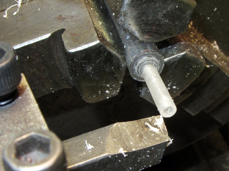
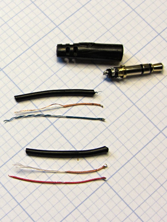
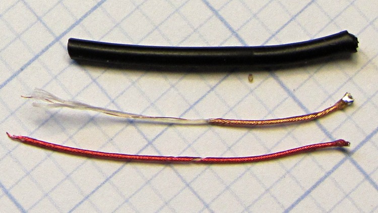
I did remember to solder the wires before assembling the pins this time…

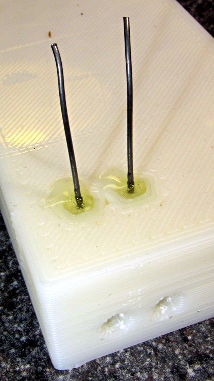
Because the pins now index on their shoulder with the springs at partial extension, I set the drills into the pin vice vise [Update: One can probably be arrested for pin vice] to produce depths displayed by the OpenSCAD program before reaming out the printed holes:
ECHO: "Depth to taper end: 24.72"
ECHO: "         ferrule end: 15.62"
ECHO: "         plug end: 4.62"
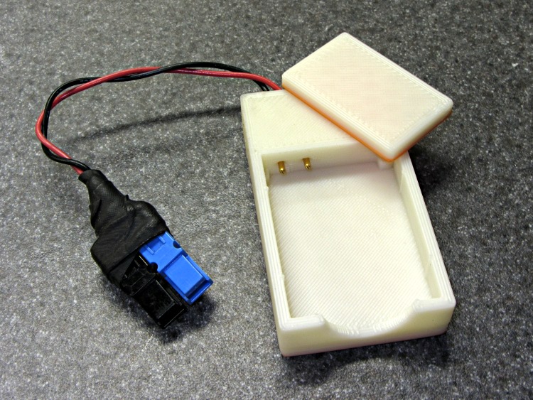
Then glue the pin plugs into the holder and the flat lid atop the case to capture the battery, clamping everything to the corner of the Sherline’s countertop:

And it Just Worked: nice travel between the limits, smooth operation, it’s the way I should have done it from the beginning*. You knew that all along, right?
Here are the three NB-5L Battery Holder versions, all snuggled up together. The longer and flatter coil-spring version sits on the right:
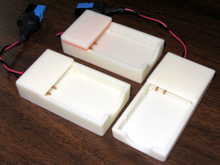
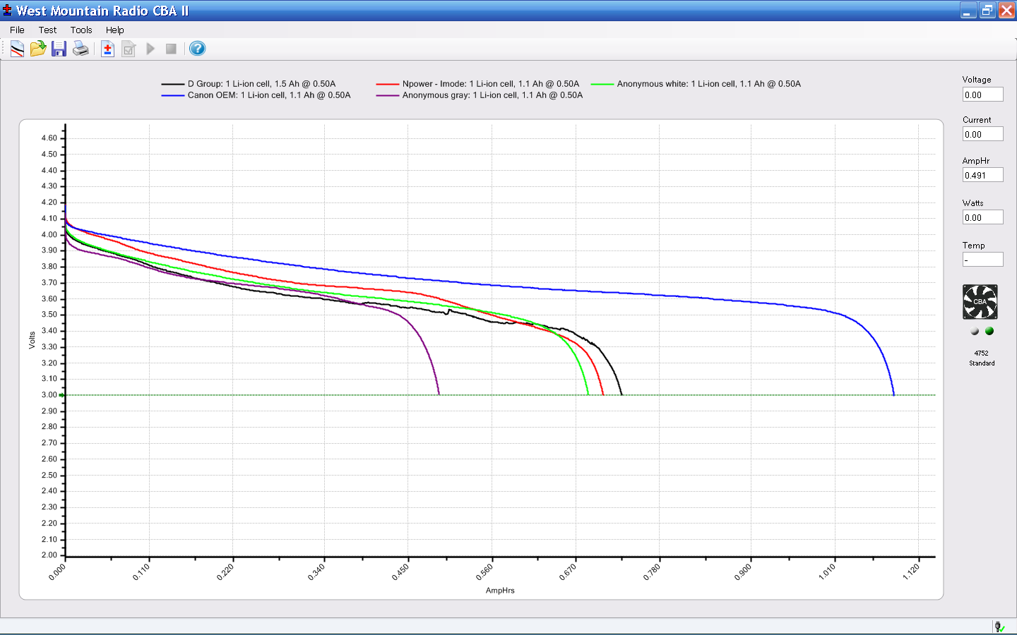
Now I can take some data…
The OpenSCAD source code:
// Holder for Canon NB-5L Li-Ion battery
// Ed Nisley KE4ZNU August 2011

include </home/ed/Thing-O-Matic/lib/MCAD/units.scad>
include </home/ed/Thing-O-Matic/lib/MCAD/boxes.scad>
include </home/ed/Thing-O-Matic/Useful Sizes.scad>

// Layout options

Layout = "Build";					// Case Lid Plugs Show Build Fit

//- Extrusion parameters - must match reality!
//  Print with +2 shells and 3 solid layers

ThreadThick = 0.33;
ThreadWidth = 2.0 * ThreadThick;

HoleWindage = 0.2;

function IntegerMultiple(Size,Unit) = Unit * ceil(Size / Unit);

Protrusion = 0.1;			// make holes end cleanly

BuildOffset = 3.0;			// clearance for build layout

//- Battery dimensions - rationalized from several samples
//  Coordinate origin at battery corner by contact plates on bottom surface

BatteryLength = 45.25;
BatteryWidth = 32.17;
BatteryThick =  7.85;

ContactWidth = 2.10;
ContactLength = 4.10;
ContactRecess = 0.85;

ContactOC = 3.18;			// center-to-center across contact face
ContactOffset = 4.45;		// offset from battery edge
ContactHeight = 3.05;		// offset from battery bottom plane

AlignThick = 2.2;			// alignment recesses on contact face
AlignDepth = 2.0;			// into face
AlignWidth1 = 0.7;			// across face at contacts
AlignWidth2 = 2.8;			//  ... other edge

//- Pin dimensions

PinTipDia = 1.6;
PinTipLength = 10.0;

PinTaperLength = 2.3;

PinShaftDia = 2.4;
PinShaftLength = 6.8;

PinFerruleDia = 3.1;
PinFerruleLength = 2.0;

PinLength = PinTipLength + PinTaperLength + PinShaftLength + PinFerruleLength;

ExtendRelax = 1.5 + ContactRecess;		// pin extension when no battery is present
ExtendOvertravel = 1.0;					//  ... beyond engaged position

//- Spring dimensions

SpringDia = 3.1;						// coil OD
SpringMax = 9.3;
SpringLength = SpringMax - 0.3;			// slightly compressed
SpringMin = 4.5;

SpringPlugDia = 5.0;					// plug retaining the spring
SpringPlugLength = IntegerMultiple(4.0,ThreadWidth);
SpringPlugSides = 12;

SpringTravel = ExtendRelax + ExtendOvertravel;

//- Holder dimensions

GuideRadius = ThreadWidth;						// friction fit ridges
GuideOffset = 10;
WallThick = 4*ThreadWidth;						// holder sidewalls

BaseThick = 6*ThreadThick;			// bottom of holder to bottom of battery
TopThick = 4*ThreadThick;			// top of battery to top of holder

ThumbRadius = 10.0;			// thumb opening at end of battery

CornerRadius = 3*ThreadThick;			// nice corner rounding

CaseLength = SpringPlugLength + SpringLength + PinLength - ExtendRelax
			+ BatteryLength + GuideRadius + WallThick;
CaseWidth = 2*WallThick + 2*GuideRadius + BatteryWidth;
CaseThick = BaseThick + BatteryThick + TopThick;

//- XY origin at front left battery corner, Z on platform below that

CaseLengthOffset = -(SpringPlugLength + SpringLength + PinLength - ExtendRelax);
CaseWidthOffset = -(WallThick + GuideRadius);
CaseThickOffset = BaseThick;

LidLength = ExtendRelax - CaseLengthOffset;

echo(str("Depth to taper end: ",
		 (SpringPlugLength + SpringLength + PinFerruleLength + PinShaftLength + PinTaperLength)));
echo(str("         ferrule end: ",
		  (SpringPlugLength + SpringLength + PinFerruleLength)));
echo(str("         plug end: ",SpringPlugLength));

//----------------------
// Useful routines

module PolyCyl(Dia,Height,ForceSides=0) {			// based on nophead's polyholes

  Sides = (ForceSides != 0) ? ForceSides : (ceil(Dia) + 2);

  FixDia = Dia / cos(180/Sides);

  cylinder(r=(FixDia + HoleWindage)/2,
           h=Height,
	   $fn=Sides);
}

module ShowPegGrid(Space = 10.0,Size = 1.0) {

  Range = floor(50 / Space);

	for (x=[-Range:Range])
	  for (y=[-Range:Range])
		translate([x*Space,y*Space,Size/2])
		  %cube(Size,center=true);

}

//-------------------

//-- Guides for tighter friction fit

module Guides() {
  	  translate([GuideOffset,-GuideRadius,CaseThickOffset])
		PolyCyl(2*GuideRadius,(BatteryThick - Protrusion),4);
	  translate([GuideOffset,(BatteryWidth + GuideRadius),CaseThickOffset])
		PolyCyl(2*GuideRadius,(BatteryThick - Protrusion),4);
	  translate([(BatteryLength - GuideOffset),-GuideRadius,CaseThickOffset])
		PolyCyl(2*GuideRadius,(BatteryThick - Protrusion),4);
	  translate([(BatteryLength - GuideOffset),(BatteryWidth + GuideRadius),CaseThickOffset])
		PolyCyl(2*GuideRadius,(BatteryThick - Protrusion),4);
	  translate([(BatteryLength + GuideRadius),GuideOffset/2,CaseThickOffset])
		PolyCyl(2*GuideRadius,(BatteryThick - Protrusion),4);
	  translate([(BatteryLength + GuideRadius),(BatteryWidth - GuideOffset/2),CaseThickOffset])
		PolyCyl(2*GuideRadius,(BatteryThick - Protrusion),4);

}

//-- Contact pins (holes therefore)

module PinShape() {

  union() {
	cylinder(r=(PinTipDia + HoleWindage)/2,h=(PinTipLength + Protrusion),$fn=6);

	translate([0,0,PinTipLength])
	  cylinder(r=(PinShaftDia + HoleWindage)/2,
			   h=(PinTaperLength + PinShaftLength + Protrusion),$fn=6);

	translate([0,0,(PinLength - PinFerruleLength)])
	  cylinder(r=(PinFerruleDia + HoleWindage)/2,
				h=(PinFerruleLength + Protrusion),$fn=6);

	translate([0,0,(PinLength)])
	  cylinder(r=(SpringDia + HoleWindage)/2,
				h=(SpringLength + Protrusion),$fn=6);

	translate([0,0,(PinLength + SpringLength)])
	  cylinder(r=(SpringPlugDia + HoleWindage)/2,h=(SpringPlugLength + Protrusion),$fn=SpringPlugSides);

	  translate([0,0,(PinLength + SpringLength + SpringPlugLength)])
	  cylinder(r=(SpringPlugDia + HoleWindage)/2,h=2*SpringPlugLength,$fn=SpringPlugSides);	// extend hole
  }

}

module PinAssembly() {

  translate([ExtendRelax,ContactOffset,CaseThickOffset + ContactHeight]) {
	rotate([0,270,0]) {
	  PinShape();												// pins
	  translate([0,(2*ContactOC),0])
		PinShape();
	}
  }

}

//-- Case with origin at battery corner

module Case() {

  difference() {

	union() {

	  difference() {
		translate([(CaseLength/2 + CaseLengthOffset),
				  (CaseWidth/2 + CaseWidthOffset),
				  (CaseThick/2)])
		  roundedBox([CaseLength,CaseWidth,CaseThick],CornerRadius); 	// basic case shape

		translate([-ExtendOvertravel,-GuideRadius,CaseThickOffset])
		  cube([(BatteryLength + GuideRadius + ExtendOvertravel),
				(BatteryWidth + 2* GuideRadius),
				(BatteryThick + Protrusion)]);						// battery space

	  }

	  Guides();

	  translate([-ExtendOvertravel,-GuideRadius,BaseThick])
		cube([(AlignDepth + ExtendOvertravel),
			  (AlignWidth1 + GuideRadius),
			  AlignThick]);											// alignment blocks
	  translate([-ExtendOvertravel,
				 (BatteryWidth - AlignWidth2),
				 BaseThick])
		cube([(AlignDepth + ExtendOvertravel),
			  (AlignWidth2 + GuideRadius),
			  AlignThick]);

	}

	translate([(-ExtendOvertravel),
			   (CaseWidthOffset - Protrusion),
			   (CaseThickOffset + BatteryThick)])
	  cube([CaseLength,
		    (CaseWidth + 2*Protrusion),
		    (TopThick + Protrusion)]);								// battery access

	translate([(CaseLengthOffset - Protrusion),
			   (CaseWidthOffset - Protrusion),
			   (CaseThickOffset + BatteryThick)])
	  cube([(CaseLength + 2*Protrusion),
		    (CaseWidth + 2*Protrusion),
		    (TopThick + Protrusion)]);								// battery insertion allowance

	translate([(BatteryLength - Protrusion),
			    (CaseWidth/2 + CaseWidthOffset),
			    (CaseThickOffset + ThumbRadius)])
	  rotate([90,0,0])
		rotate([0,90,0])
		  cylinder(r=ThumbRadius,
				   h=(WallThick + GuideRadius + 2*Protrusion),
				   $fn=22);											// remove thumb notch

	PinAssembly();

  }

}

module Lid() {

  difference() {
	translate([0,0,(CaseThick/2 - BaseThick - BatteryThick)])
	  roundedBox([LidLength,
				 CaseWidth,CaseThick],CornerRadius);

	translate([0,0,-(CaseThick/2)])
	  cube([(LidLength + 2*Protrusion),
		    (CaseWidth + 2*Protrusion),
		    (CaseThick)],center=true);
  }

}

module PlugShape() {

  difference() {
	cylinder(r=SpringPlugDia/2,h=SpringPlugLength,$fn=SpringPlugSides);
	translate([0,0,-Protrusion])
	  PolyCyl(PinShaftDia,(SpringPlugLength + 2*Protrusion),SpringPlugSides/2);
  }
}

module Plugs() {
  translate([0,ContactOC,0])
	PlugShape();
  translate([0,-ContactOC,0])
	PlugShape();
}

//-------------------
// Build it!

ShowPegGrid();

if (Layout == "Case")
  Case();

if (Layout == "Lid")
  Lid();

if (Layout == "Plugs")
  Plugs();

if (Layout == "Show") {								// reveal pin assembly
  difference() {
	Case();

	translate([(CaseLengthOffset - Protrusion),
			   (CaseWidthOffset - Protrusion + WallThick + ContactOffset + ContactOC),
			   (BaseThick + ContactHeight)])
	  cube([(-CaseLengthOffset + Protrusion),
			 (CaseWidth + 2*Protrusion),
			 CaseThick + BaseThick - ContactHeight + Protrusion]);

	translate([(CaseLengthOffset - Protrusion),
			   (CaseWidthOffset - Protrusion),
			   -Protrusion])
	  cube([(-CaseLengthOffset + Protrusion),
			 (WallThick + GuideRadius + ContactOffset + Protrusion),
			 CaseThick]);
  }

  translate([ExtendRelax,ContactOffset,(CaseThickOffset + ContactHeight)]) {	// pins
	rotate([0,270,0]) {
	  %PinShape();
//	  translate([0,(2*ContactOC),0])
//		%PinShape();
	}
  }

  translate([CaseLengthOffset,ContactOffset,(CaseThickOffset + ContactHeight)])
	rotate([0,90,0])
	  PlugShape();
}

if (Layout == "Build") {
  translate([-(CaseLength/2 + CaseLengthOffset),-(CaseWidthOffset - BuildOffset),0])
	Case();
  translate([0,(CaseLengthOffset/2 - BuildOffset),0])
	rotate([0,0,90])
	  Lid();
  translate([CaseLengthOffset - SpringPlugDia,-CaseWidth/2,0])
	Plugs();
  translate([(CaseLengthOffset + SpringPlugDia),-CaseWidth/2,0])	// extra set of plugs
	Plugs();
}

if (Layout == "Fit") {
  Case();
  translate([(-LidLength/2 + ExtendRelax),
			(CaseWidth/2 + CaseWidthOffset),
			(BaseThick + BatteryThick)])
	  Lid();
  translate([ExtendRelax,ContactOffset,CaseThickOffset + ContactHeight]) {	// pins
	rotate([0,270,0]) {
	  %PinShape();
	  translate([0,(2*ContactOC),0])
		%PinShape();
	}
  }

  translate([CaseLengthOffset,
			(ContactOffset + ContactOC),
			(CaseThickOffset + ContactHeight)])
  rotate([0,90,0])
	Plugs();

}
(*) Modulo, of course, simply buying a $5 charger from eBay and gutting it. What’s the fun in that?