Ed Nisley's Blog: Shop notes, electronics, firmware, machinery, 3D printing, laser cuttery, and curiosities. Contents: 100% human thinking, 0% AI slop.
Well, it turns out that the DVD drive I stuffed into that case really does require a whole bunch of current. I tried playing a DVD and got erratic results, including weird keyboard (!) failures. Finally, I hitched a bench supply to the coaxial power jack on the case and caught it in the act:
Laptop DVD – current display
That jack normally connects to the power-only USB cable, which implies an upper limit of 100 mA. A bit of poking around inside shows that the coaxial power jack simply parallels the USB jack’s VCC line, so there’s no fancy negotiation or current sharing going on.
When the keyboard went nuts it was sharing an unpowered USB hub with this thing, which means that the overcurrent dragged down the hub’s supply. I was permuting all the choices to see if the failures suggested anything; eventually it did.
A bit of rummaging in the Basement Laboratory Warehouse Wing uncovered a 5.0 V 3.7 A wall wart switching power supply that is grossly in excess of the drive’s 1.5 A rating. Amazingly, it even had the correct coaxial power plug on the end of the cable, which never happens.
Alas, because the external supply back-powers the USB data cable, it lights up the Q150’s power button when the PC is turned off. I think I can insert an isolation diode into the USB power trace to isolate it from the jack, somewhat along the lines of that hack. However, that seems to require removing the USB connector to uncover a very well protected top trace. For now, I’ll just unplug the drive.
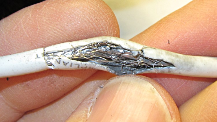
I cable-tied the mic/earphone cable on Mary’s bike helmet to a rib on the fancy air vents near the back end, hoping that would reduce the inevitable flexing. Alas, it didn’t work out that way and the cable lasted only two seasons. This cut-away view shows the pulverized shield braid inside the jacket:
Fatigue-failed helmet cable
The symptoms were totally baffling: the mic worked perfectly, but the earphones cut out for at most a few syllables. Of course, I can’t wear her helmet and it only failed occasionally while riding. I barked up several wrong trees, until it got so bad that I could make it fail in the garage while listening to the local NWS weather radio station.
I spliced in a new USB male-A connector and (re-)discovered that the braid seems to be aluminum, rather than tinned copper. In any event, the wire is completely unsolderable; I crimped the braid from the new connector to a clean section of the old braid. The braid serves only as an electrostatic shield, as it’s not connected to anything on the helmet end. That should suffice until I rebuild the headsets this winter.
The keyboard on my trusty HP 48GX calculator finally deteriorated to the point of unusability, so I tore the thing apart following the useful instructions there. The warning about applying force to the rivets that hold the case halves together gives you not the faintest concept of how much force is actually required to pry the mumble thing apart at the battery compartment; I finally invoked force majeure with a chisel scraper…
HP-48GX case rivets
I expected the calculator would not survive this operation and I wasn’t disappointed.
An HP 50g is now in hand. Here in late 2011 I’d expect HP’s top-of-the-line RPN calculator to sport a crisp high-resolution display, but noooo the low-contrast 131×80 LCD seems teleported directly from the latter part of the last millennium. The manuals are PDFs, which is OK, but their content is far inferior to the HP 48GX manuals. In particular, the editing / proofreading is terrible. I infer that the HP calculator division can barely fog a mirror and is on advanced life support; HP’s diverting all their money to, uh, executive buyouts or some other non-productive purpose.
The fact that HP sells new-manufacture HP 15C calculators doesn’t crank my tractor, even though I lived and died by one for many years. A one-line 7-segment display doesn’t cut it any more, even if the new machinery inside allegedly runs like a bat out of hell.
My HP 16C, now, that one you’ll pry out of my cold, dead hands. At one point in the dim past, I’d programmed the Mandelbrot iteration into it to provide bit-for-bit verification of the 8051 firmware for the Mandelbrot Engine array processor I did for Circuit Cellar: slow, but perfect. That calculator has a low duty cycle these days, but when I need it, I need it bad.
Having had my old ICOM IC-Z1A HT stop working, most likely due to the innards finally shaking loose, I replaced it with a Wouxun KG-UV3D dual-band radio. Unfortunately, the interface box I designed to connect the Byonics TinyTrak 3+ GPS modem, the helmet earbud/mic, and the external battery pack to the Z-1A doesn’t work with the Wouxun. It’s all different:
Mechanical interface to the radio
Battery voltage
Power control
Mic level
PTT interface
I modified the interface box from my bike thusly:
GPS-HT Interface Circuit Mods for Wouxun
Because the KG-UV3D uses the Kenwood HT interface with a single ground for mic, speaker, and PTT functions, there’s no need for galvanic isolation; all the optoisolators & the audio transformer will Go Away when I rebuild it.
The plug connections:
Wouxun KG-UV3D Mic & Speaker Jacks
Tip
Ring
Shell
3.5 mm
+5 V
Mic audio
PTT
2.5 mm
Speaker audio
Buttons
Ground
One distressing change: the IC-Z1A mic power was 3.5 V behind 400 Ω = 6 mA into an optoisolator LED, but the KG-UV3D puts 5 V behind 50 kΩ = 100 µA into a dead short. I think the voltage will suffice to drive a logic-gate MOSFET to switch the power through a PNP transistor, but, for the moment, I hotwired OK1 and “control” the interface power by unplugging the external battery. The radio runs from its own snap-on Li-Ion pack.
The PTT now has a separate logic wire and is no longer multiplexed as a DC current on the audio line. The hack on OK2 was the easiest way to make that happen on the existing board, but the TT3 PTT Out line can probably drive the PTT directly.
I’m not happy with the audio levels; the KG-UV3D requires more mic gain (which change doesn’t appear in the mods) and more TT3 output. Having tediously calibrated the TT3 for the IC-Z1A, I’m not looking forward to doing that again. I still like using an analog multiplexer to switch the audio signal, though, because it doesn’t mix the machine noise with the voice transmissions.
Bungied GPS Interface Box
There being no way to mount the box on the radio and no way to control the interface power if I did, I simply lashed it to the side of the pack holding the radio behind the seat. Obviously, that can’t last forever…
I think the KG-UV3D stuffs more RFI into the mic circuit, because that box is now in the only position that doesn’t result in weird voice audio dropouts. Given the precarious nature of the thing, though, I must look again after getting it in a box on the radio.
Earth to amateur radio manufacturers: seen from out here, it’d be perfectly OK to standardize some of this stuff!
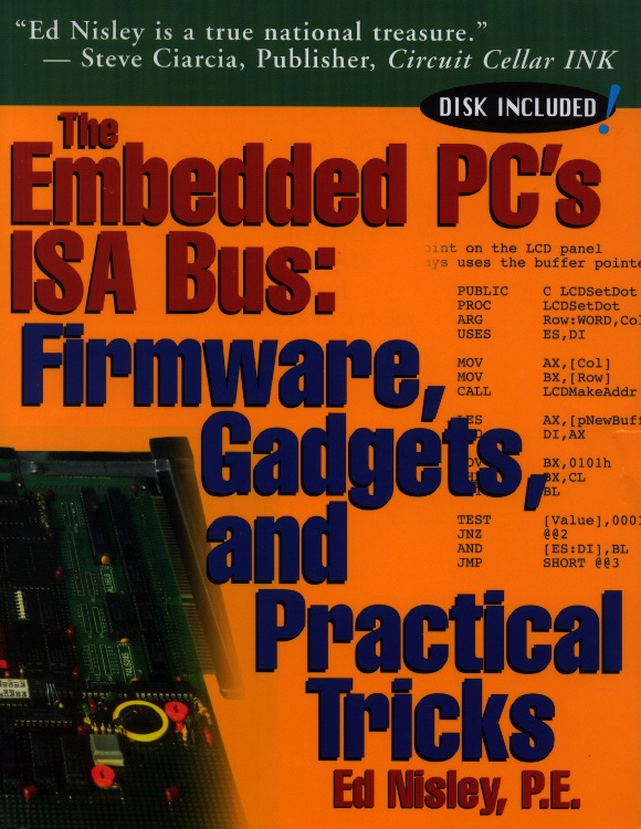
A long time ago, in a universe far away, I wrote a book that (barely) catapulted me into the ranks of the thousandaires. Time passes, companies get sold / fail / merge / get bought, and eventually the final owners decided to remainder the book; the last royalty check I recall was for $2.88.
Anyhow, now that it’s discontinued and just as dead as the ISA bus, I own the copyright again and can do this:
The ZIP files are disguised as ODT files so WordPress will handle them: rename to get rid of the ODT extension, unzip, and you’re good to go.
The big ZIP has the original pages laid out for printing, crop marks and all, so this is not as wonderful a deal as it might first appear. Update: A kind reader (you know who you are: thank you!) applied suitable magick to produce the “reformatted” PDF for easier reading & printing.
The little ZIP has the files from the diskette, which was garbled right from the start. I think all the cartons passed over a conveyor with a powerful magnetic latch.
Note, however, that I do retain the copyright, so if you (intend to) make money from them, be sure to tell me how that works for you.
Words cannot begin to describe how ugly that front cover really is, but Steve’s encomium still makes me smile.
The text and layout is firmly locked inside Adobe Framemaker files, where it may sleep soundly forever. The only way I can imagine to get it back into editable form would be to install Windows 98 in a VM, install Framemaker, load up the original files, and export them into some non-proprietary format. Yeah, like that would work, even if I had the motivation.
If you prefer a dead-tree version, they’re dirt cheap from the usual used-book sources. Search for ISBN 1-57398-017-X (yes, X) and you’ll get pretty close.
Or, seeing as how I just touched the carton of books I’ve been toting all these years, send me $25 (I’m easy to find; if all else fails, look up my amateur callsign in the FCC database) and get an autographed copy direct from the source. Who knows? It might be worth something some day…
Of late, something in the pile of input devices attached to my main PC has been feeding occasional bursts of upward scroll commands, to the extent that editing long documents (something I do quite a bit of, oddly enough) was becoming difficult. By process of elimination, the culprit turned out to be the Kensington trackball to the left of the keyboard: unplugging it eliminated the problem.
Having had problems with that thing before and having gotten considerable feedback from other folks, I had a general idea of how to proceed: putz with the IR emitter-detector pair, but not very much. A side view of the pair with the trackball cup and scroll ring removed:
Scroll ring IR emitter-detector quadrature pair
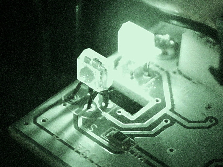
Now, what’s weird about that setup is that the detector lens seems to be pointing in the wrong direction: away from the emitter’s lens. You know it’s the detector because it’s tinted: there’s no point in filtering the emitter’s output (although I have seen gray-tinted IR LEDs, which I think is just to mark them as different from visible LEDs). Here’s proof: a pure IR picture from my Sony DSC-F717 in Nightshot (a.k.a. IR) mode through a Hoya R72 visible-block filter:
Quadrature pair in pure IR
Some possibilities for why the detector is backwards:
It’s an assembly screwup (unlikely, but possible)
That’s not a lens, it’s a locating tab (different on emitter & detector?)
The backside uses the metal conductors as slits to enhance the signal (my favorite)
Here’s a grossly image-enhanced blowup of the detector from that picture:
Quadrature IR detector in pure IR – detail
The case becomes transparent in pure IR, so you can see the metal lead frame inside. I think they’re using the gaps between the leads to enhance the contrast of the scroll ring edges passing through the beam: absolutely no IR except when a gap aligns with a scroll ring opening.
[Update: read the comments for a different interpretation; I’m probably wrong.]
That would also explain why the pair seems so sensitive to alignment: there’s very little IR hitting the detector, because the IR illumination passes through the transparent-to-IR case and vanishes out the far side, with only a tiny bit reflected to the sensor!
Anyhow, I pushed the pair minutely toward each other, just enough to feel the leads bend, and put everything back together. So far it seems to be working perfectly, but it’s done that before …
[Comment: Jack found a different solution that might produce better results:
Just got the Problem with my Scroll ring and thanks to your blog i digged a bit deeper.
here is the Solution for my Problem:
I checked this while connected and i found that bending worked only for a short time, so i gave a closer look to the contacts.
all are soldered from below BUT two contacts are on the upper side. normaly solder should flow into but here it was as simple as just resolder the receiver with enough solder an its now working again. (btw a realigned the magnet to get a better response)
Thanks Jack
ps. the size of the cuts in the metall from the scroll ring differ, a shame for that price..
It’s certainly worth trying, particularly when your Expert Mouse trackball isn’t working…