Aitch bestowed this gem on me while cleaning out his collection:
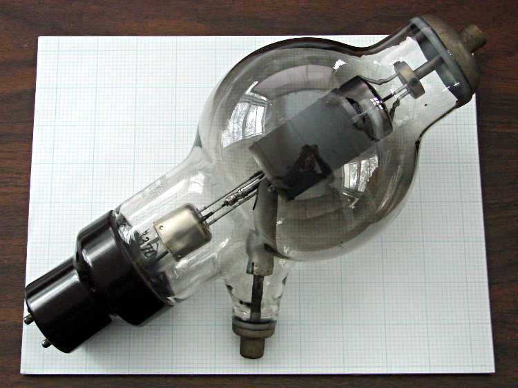
It’s a 6C21 triode, originally used as a radar modulator, atop a letter-size sheet of graph paper. The plate terminal is on top, the grid sticks out to the side, and the filament is common with the cathode through the base pins.
It has impressive specs (datasheet and pictures):
- 30 kV plate voltage
- 15 A pulsed plate current, 100 ms max
- 7.5 V filament at 15 A = 112 W (!)
- Pulse duty cycle 0.2%
The gray film inside the bulb shows that it’s been used, but the filament still has continuity. Ordinarily, you could turn something like this into a night light by running the filament at a voltage somewhat under its rating, but my bench supply maxed out at @ 3 A without even warming it up; a dim orange night light that burns maybe 75 W is Not A Good Idea.
The base has some intriguing holes, originally used for forced-air cooling, that lead directly to the glass envelope:
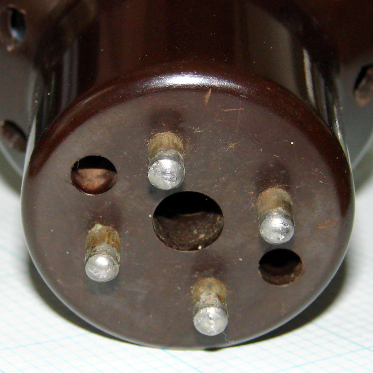
One could mount discrete LEDs in those holes, maybe a slightly turned-down 10 mm cool-white LED in the middle flanked by red and blue, and run a low-power Arduino-based mood light; by some cosmic coincidence, the hole spacing matches up almost perfectly with those LED strips. Or one could go full analog with three red LEDs driven by the WWVB signal.
I’m thinking a plain black acrylic case, with the tube base sunk into the middle, would be about right. No readouts, no dials, no buttons, just a gently glowing tube.
Maybe a 3D printed socket holding everything in place?