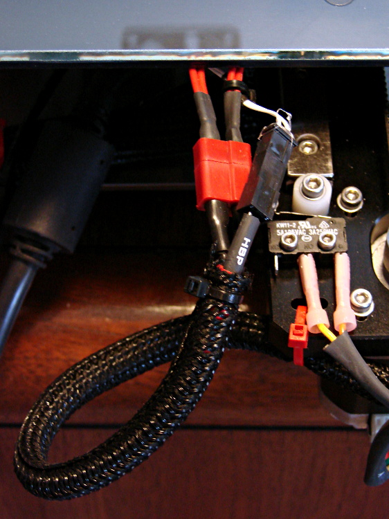
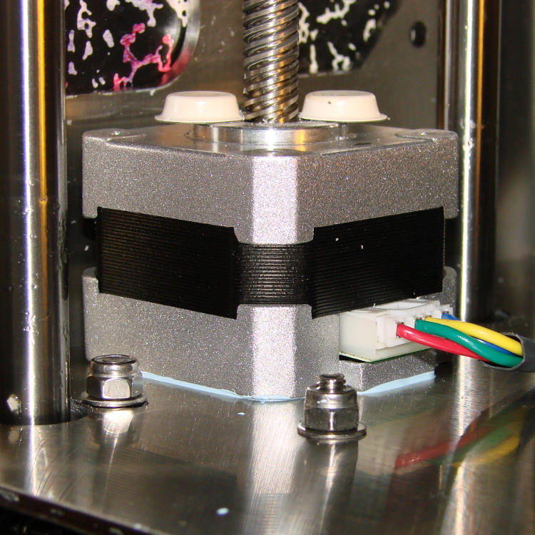
Several users have observed that the stepper motor driving the M2’s Z axis leadscrew gets very hot. I measured about 140 °F = 60 °C on the as-built motor, so I loosened the screws and raised the motor slightly:
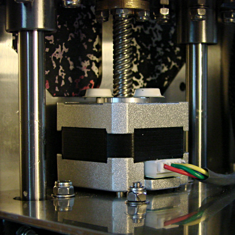
I eased some heatsink compound underneath by putting dabs on a slip of paper and painting it on the bottom of the motor case, lowered the Z stage to the bottom of its travel, and tightened the mounting screws:
That reduced the temperature to about 120 °F = 50 °C, which still seemed excessive for a short-stack motor mounted on a fairly large chunk of stainless steel. The motor also sounded quite rough during homing and long manual moves, sooo … something was wrong. I bet you know where this is going, right?
Let’s start with the firmware side and determine what current the motor should be seeing.
The M2 uses a slightly modified version of the Marlin firmware running on a RAMBo 1.1b board. The basic RAMBo doc gives these equations relating the peak winding current Imax to the constant W that defines it in the firmware:
Vref = 0.8 * Imax
W = 255 * (Vref / 1.66)
Mashing those together produces this:
W = 255 * (0.8 * Imax) / 1.66
The default Z axis stepper current constant W (called Z_CURRENT in the Marlin source) is 135. The board in my M2 has R30 = 3.3 kΩ, which sets the maximum possible current to 2 A. Working the equation backwards, a Z_CURRENT = 135 will produce a peak winding current of 1.1 A.
However, a nearby comment in the source code suggests this is should be about 0.75 A. The original RAMBo board had a maximum possible current of 1.5 A, but running those numbers doesn’t agree. Another comment suggests 185 corresponds to about 1 A, which isn’t right, either. There’s nothing new about stale comments not corresponding to the actual hardware; I’ve done that myself.
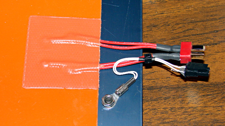
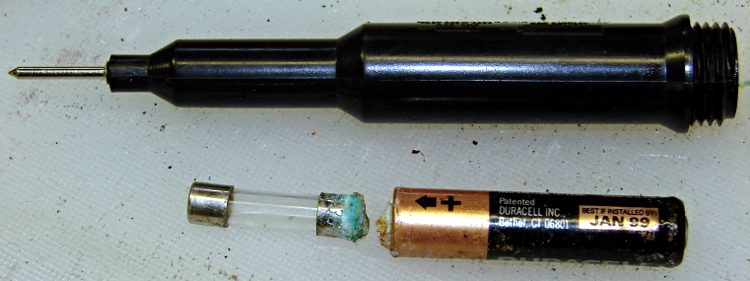
With 1.1 A in hand, let’s unplug the cable and measure the winding resistance.
Not much to my surprise, the motor has 28 Ω windings. The M2 uses a 19 V supply for the steppers, so the maximum motor current works out to 19 V/28 Ω = 680 mA, but it must be less than that to allow the microstepping controller to manage the current.
It seems that Makergear is connecting a high-resistance stepper intended for a simple H-bridge drive to a high-performance microstepping controller. For some background on why that combination doesn’t work, see my analysis of the original MBI Thing-O-Matic steppers.
I thought we all agreed we weren’t going to do that any more. Maybe nobody sells a low-resistance motor-with-integral-leadscrew?
Anyhow.
The only thing to do in the short term is to reduce the peak current to a rational value around 600 mA:
74 = 255 * (0.8 * 0.6) / 166
I set it to a nice, round 75 and reloaded the firmware, which immediately made the motor hum, rather than growl, on long moves. The case temperature didn’t drop by very much, because the poor motor still dissipates about 11 W, not much less than the original 13 W. There’s only so much heat you can pull out of the case and these little motors are actually rated for maybe 5 W, tops.
The motor’s overall performance didn’t change, which is good, because it didn’t have much performance to begin with. The X and Y motors can accelerate at 9000 mm/s2, but the Z motor limit is 30 mm/s2; it doesn’t really accelerate, it sort of gains momentum in a stately manner.
Next: let’s see if it really matters.