Ed Nisley's Blog: Shop notes, electronics, firmware, machinery, 3D printing, laser cuttery, and curiosities. Contents: 100% human thinking, 0% AI slop.
No snagging on a bulky quilt shoved through the machine
Not completely butt-ugly
Reasonably durable
I picked up reels of cool-white and warm-white waterproof LED strips (12 V, 3528-size chips, 5 m, 600 LED, 25 mm segments) from the usual eBay supplier, who promptly charged for both and shipped only the warm-white reel. Cool-white LEDs will be a better color match to daylight from the window and the little Ottlite she uses for detail work, but I ran some prototypes while we wait for the replacement.
The Chinese New Year really comes in handy as an excuse for screwing things up and not responding for a week or two. ‘Nuff said.
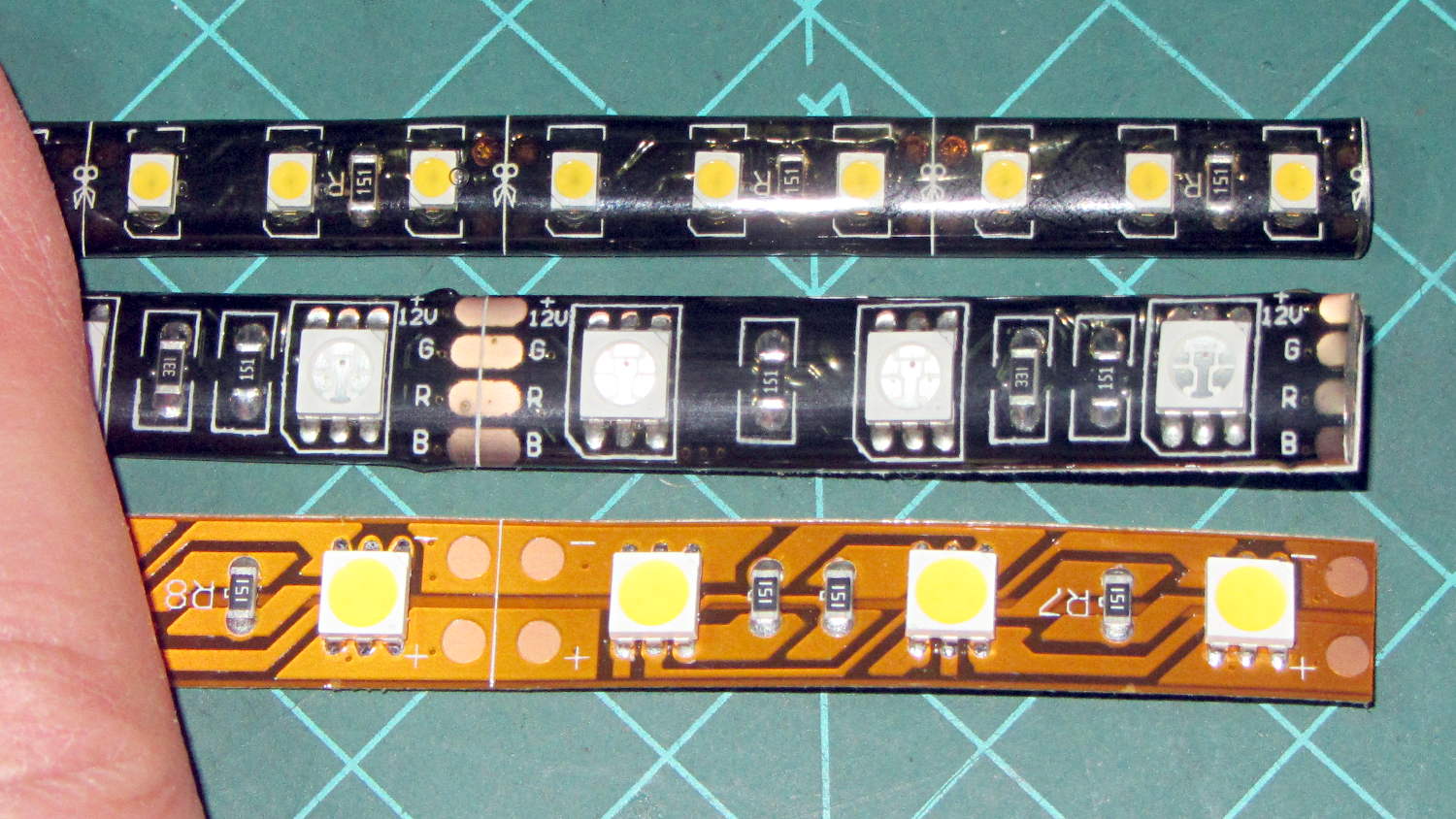
They’re similar to the RGB LEDs from a while ago, with even gummier “waterproof” encapsulation. I got double-density 600 LED strips to put more light emitters across the arm:
Various LED strip lights
The smaller 3528 SMD LEDs (vs. 5050 chips in the others) allow a narrower strip and the double-density layout means each three-LED segment is half as long long. The as-measured dimensions work out to:
25.0 mm segment length
8.2 mm strip width
2.5 mm thickness
The sealant thickness varies considerably, so I’d allow 3.0 mm for that in case it mattered. It slobbers over the edge of the strip here and there; allowing at least 9.0 mm would be wise.
The SMD resistor in each segment is 150 Ω. A 5 segment length drew 85 mA @ 12 V = 17 mA/segment. Boosting the voltage to 12.8 V got the current to the expected 100 mA = 20 mA/segment.
The LEDs are noticeably less bright than the 5050 LEDs, even at 20 mA/segment, but I think they’ll suffice for the task.
Removing the camera’s front cover (stick the screws to a length of masking tape!) reveals the backup battery hasn’t magically healed itself:
Casio EX-Z850 backup battery – corrosion
The main battery applies 3.2 V with the top terminal negative; it’s marked to help me remember that fact.
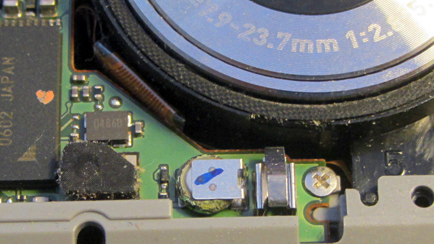
I snipped both legs of the top contact bracket, which promptly fell off, and then pushed the battery off its bottom contact. The condition of those two pads suggests a pair of cold solder joints (clicky for more dots):
Casio EX-Z850 backup battery – contact pads
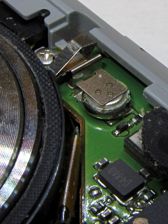
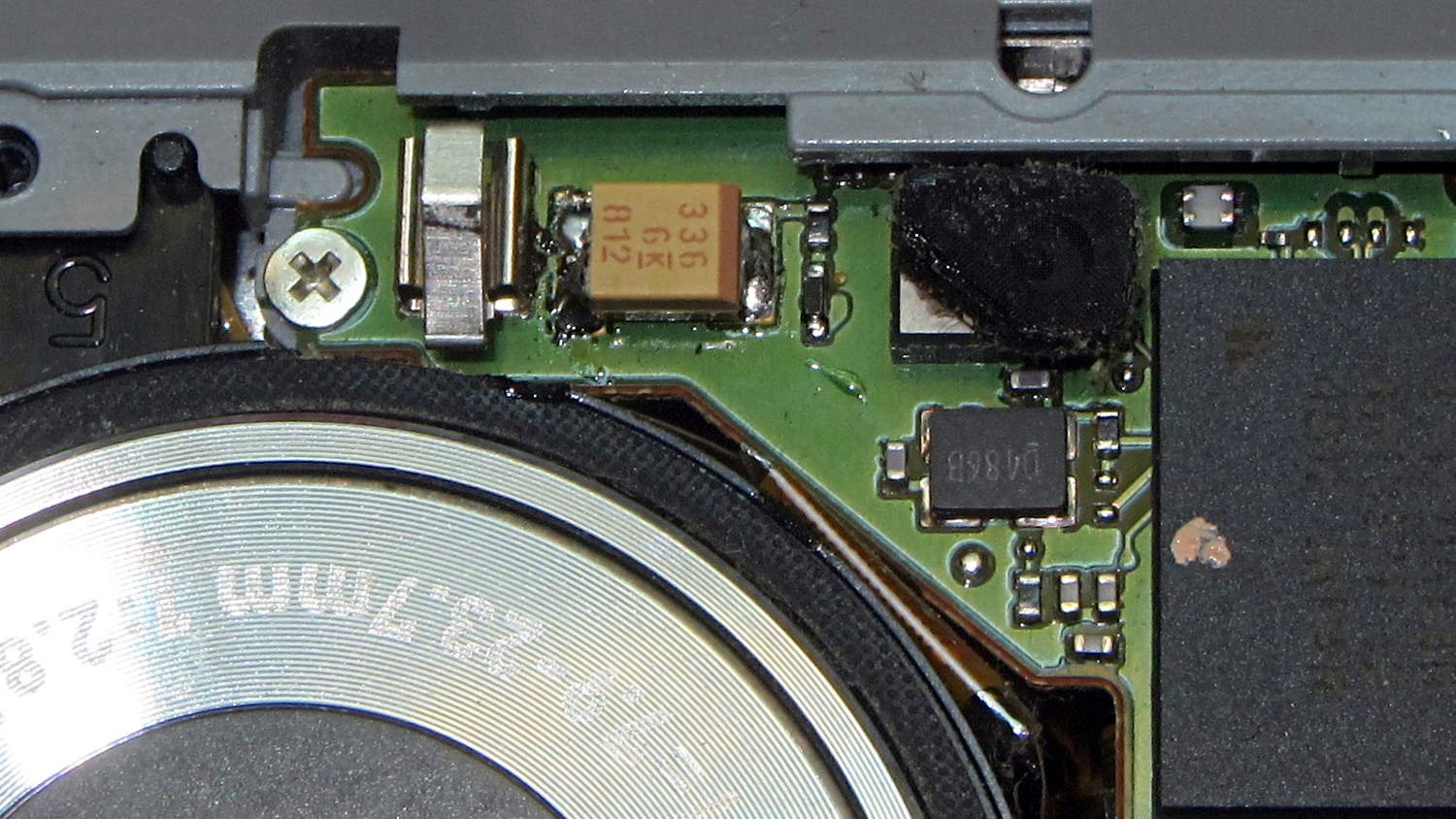
I wanted to replace it with a polyacene supercap, but there’s just not enough room in there. The biggest cap that fit was a 33 μF 16 V SMD electrolytic cap, so I soldered one in place:
I had to flip the camera around to get the soldering iron in between the cap and what looks to be an intrusion monitoring switch just to its left. No lie, that shiny metal thing seems to be a tab that presses against the front cover; it could be a static discharge / grounding point, but the base looks more complex than that.
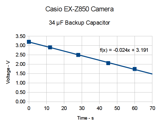
Now, a capacitor isn’t a battery, but memory backup doesn’t require much of a battery, either. I guesstimated the memory (or whatever) would draw a few microamps, at most, giving me a few seconds, at least, to swap batteries. A quick measurement shows that I’ll have plenty of time:
Casio EX-X850 backup capacitor – voltage vs time
The camera started up fine after that adventure, so the memory stays valid with the backup voltage down around 1 V.
The cap measured 34 μF, so a voltage decline of 24 mV/s works out to:
IC = C (dV/dT) = 34 μF x 24 mV/s = 820 nA
So, at least at room temperature, the memory draws less than a microamp.
I love it when a plan comes together!
With any luck, that capacitor should outlast the rest of the camera. It’ll definitely outlast a lithium battery, even if I could find one to fit in that spot.
I did those measurements by sampling the capacitor, rather than holding the meter probes in place, because the300 nA of current drawn by a 10 MΩ input resistance would cause a pretty large measurement error…
My trusty Radio Shack Sound Level Meter recently began misbehaving: switching to the most sensitive two ranges (-60 and -70 dB) caused it to turn off. Finessing the switch got it back in operation, so I completed the mission (a string quartet in Vassar’s Skinner Recital Hall topped out around 90 dB) and laid it out for repair:
Radio Shack Sound Level Meter – PCB solder side
After cleaning the already pristine gold-plated (!) contact pads and putting it back together, the switch failed the same way.
A bit more poking & prodding revealed that slightly loosening the upper case screw (in the boss just left of the switch pads) made it work perfectly.
Ah-ha!
Come to find out that the rear case presses on the PCB to hold it in place, which moves it slightly toward the front of the case. The switch rotor, being firmly attached to the stem in the middle of the pads, doesn’t move, which suggested that the bifurcated spring contacts on the rotor had take a bit of a set.
Un-bending them very, very gently to add a millimeter of springiness solved the problem.
A piano solo topped out in the high 80s…
Update: Another meter owner shows how to cure the problem, rather than treat the symptom:
I found your older note about the switch problem on the digital R.S. SLM to be helpful, in that mine had a similar problem, but only on the 60 dB scale, not both the 60 and 70 dB scales. Your diagnosis about the back putting pressure on the board seems to be right on. However, for me, re-bending the switch contacts didn’t help.
What did fix it was filing ~2mm off the back case boss around the upper screw hole. That was the source of the pressure on the board. 1 mm didn’t quite fix it, but 2mm off did.
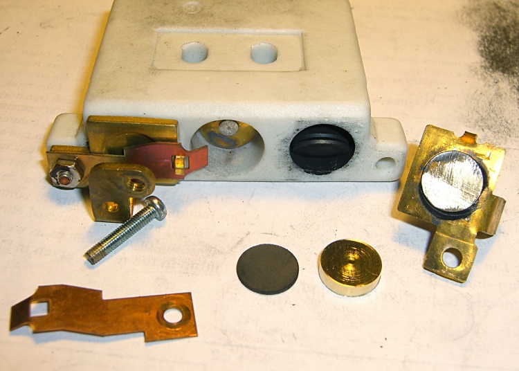
The speed control pedal on Mary’s sewing machine once again started racing away from a dead stop, which we now know means more disks inside the carbon pile rheostat have disintegrated. It looked pretty much the same as when I took it apart in 2009:
Rheostat graphite wafers and contacts
This time, it had one cracked wafer and several thin ones, reducing the length of the stacks so much that the pedal exerted very little force (thus, not starting the motor) before the shorting contacts caused a runaway.
Back then, I’d machined two brass disks to fill the empty space:
Rheostat with brass spacer button
A rough measurement showed I’d have to double their thickness to about 7 mm each, but it seemed like replacing high-resistance carbon with low-resistance brass wasn’t a Good Idea, at least when taken to an extreme. Not knowing what would count as an extreme in this situation, I decided to replace the brass disks with graphite cylinders sized to fill up the empty space.
The Little Box o’ Machinable Graphite produced a small bar, from which I sliced a square with jeweler’s pull saw:
Machineable Graphic – rough-sawn slab
Cutting that in half, then one of the bars in half, produced a pair of cubes:
Machineable Graphic – cubes
I tried sanding off the corners:
Machineable Graphic – sanded cube
After it became painfully obvious that process would take just slightly less than forever, I deployed the Dremel sanding drum:
Machineable Graphic – cylinders
Much to my surprise, the shop vacuum didn’t quite inhale the cloth, I didn’t drop either of the cylinders into its gaping maw or sand away my fingertips, and the cylinders emerged more-or-less good looking. I sanded the faces reasonably smooth and parallel, removed a few high spots left by the Dremel, and the cylinders slid neatly into the holes in the ceramic rheostat.
I felt a definite kinship with those guys in the rackets (not squash, as I once knew) court under the stadium seats…
I put the cylinders at the end of the stacks, against the graphite buttons (shown in the top picture), and left the disks to settle themselves against the brass contacts. In retrospect, I should have put the cylinders against the brass, so that the inevitable erosion will chew on the (relatively) easily replaced bulk cylinders.
Each graphite cylinder displaced six disks, so now I have some spares for next time. I’m certain that the graphite has lower resistance than the equivalent length of disks, but it’s probably higher than the same length of brass. I was not going to slice those cylinders into disks.
After vigorous and repeated handwashing with gritty cleaner after leaving the Basement Laboratory Workshop, the pedal assembly went back together smoothly and, once again, operates the way it should: controllable smooth low speeds, crazy-fast high speeds, and a steady transition between the two. Mary has resumed quilting up a storm.
That shop vacuum may never forgive me, but it totally eliminated all the carbon dust from the work area. The filter started out coated with a generous layer of dust and crud, so I’m pretty sure it collected most of the very fine dust, too.
I briefly considered using the lathe, but came to my senses.
The cheap way to do AC motor speed control involves a triac chopping the sine wave, so as to produce all manner of hash above and beyond the usual motor commutation noise. It occurs to me that the sewing machine has a universal motor that would run just as happily on 120 V DC as it does on AC, so a cheap 120 V DC supply (around 2 A should suffice) from the usual eBay supplier and a high voltage MOSFET on a generous heatsink would work even better. One might even get by with just a full-wave rectifier bridge and pulsating DC.
The rheostat doesn’t dissipate more than a few watts, I think, so thermal management should not pose a serious problem.
The motor rating says it’s good for 1 A, which means the power should be less than a few tens of watts. Some resistance and current measurements are in order.
You can actually buy replacement pedals, but what’s the fun in that?
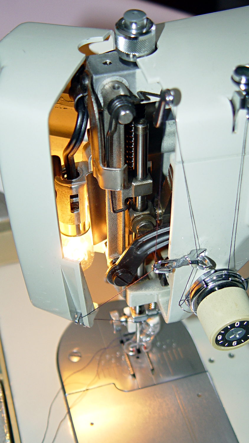
Mary wants more light directly around the needle of her Kenmore Model 158 sewing machine, as the existing light (a 120 V 15 W incandescent bulb tucked inside the end housing) casts more of a diffuse glow than a directed beam:
Kenmore Model 158 Sewing Machine – lamp
The end cap fits snugly around the bulb, but I thought a pair of 10 mm white LEDs, mounted side-by-side and aimed downward at the cover plate, would work. Of course, plugging a pair of white LEDs into a 120 VAC socket won’t work, but some judicious rewiring and a new 12 V DC wall wart will take care of that.
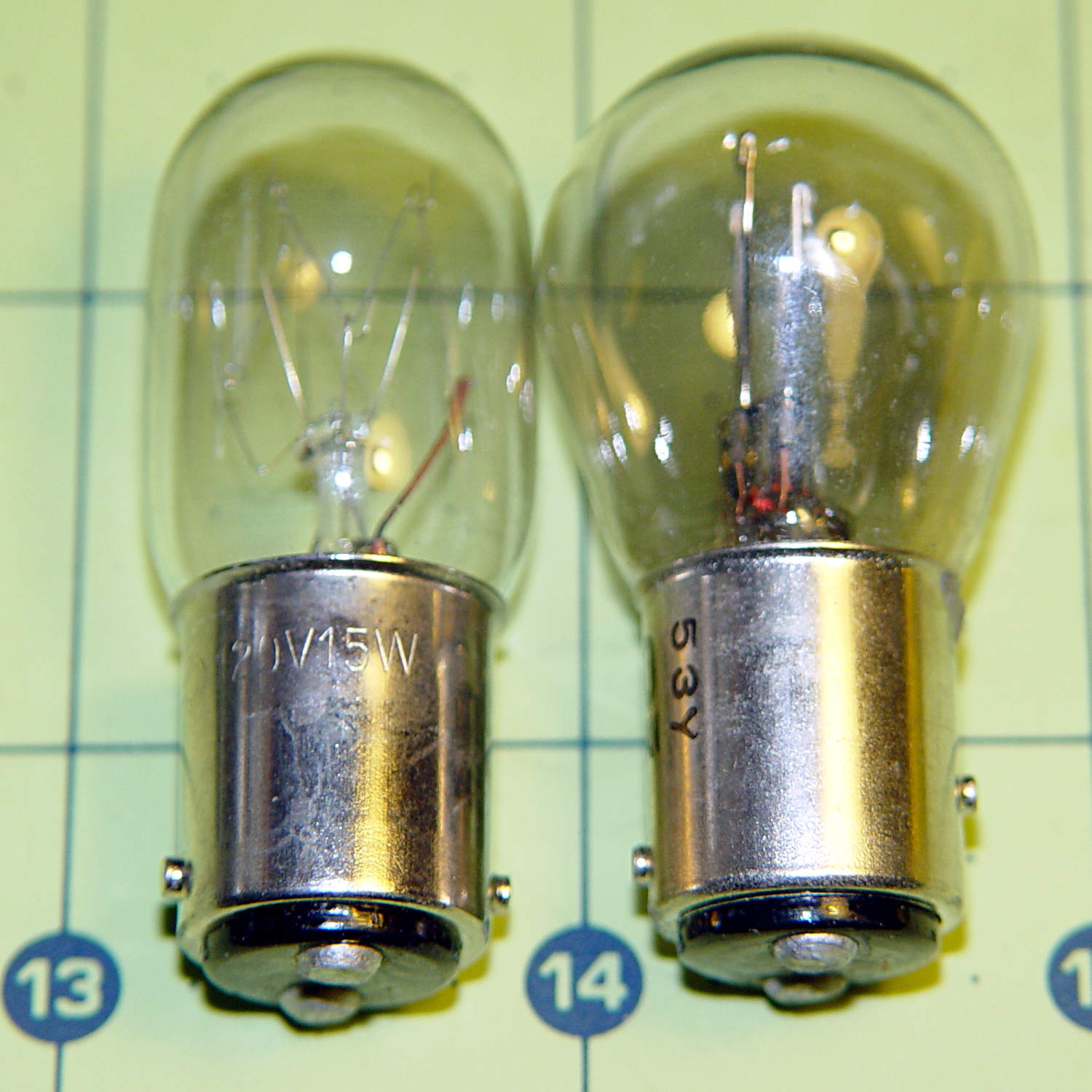
The bulb has a dual-contact bayonet base, with both pins isolated from the shell and connected to the non-polarized (!) line cord through the power switch. I didn’t know it was called a BA15d base, but now I do.
A 12 V automotive brake/taillight bulb (type 1157, I think) pulled from the Big Box o’ Bulbs has a slightly different pin arrangement that keys the filaments (which are not isolated from the shell) to the surrounding reflector:
BA15d Bayonet Bulb Bases – 120V vs. 12V pins
So I conjured a mockup to see if it would fit, using 2-56 screws to mimic whatever hardware might be practical:
BA15d Bulb – LED Adapter
The solid model shows how it all fits together:
Sears Lamp LED Adapter – Show view
The two tiny ruby-red pins represent filament snippets in alignment holes, barely visible in real life:
It actually fit pretty well, ignoring the fact that the LEDs point 90° from the intended direction (so I could see how the holes came out inside the pivot, honest), and lit up the area quite well, but it’s such a delicate affair that removing the entire socket and replacing it with a dedicated metal bracket / heatsink for two high-power SMD LEDs will be better.
The OpenSCAD source code:
// Adapter for LEDs in Sears sewing machine lamp socket
// Ed Nisley - KE4ZNU - January 2014

Layout = "Show";		// Build Show LEDTab LEDPlate ShellMount

//- Extrusion parameters must match reality!
//  Print with 2 shells and 3 solid layers

ThreadThick = 0.20;
ThreadWidth = 0.40;

HoleWindage = 0.2;			// extra clearance

Protrusion = 0.1;			// make holes end cleanly
Gap = 2.0;					// spacing between Show parts

AlignPinOD = 1.70;			// assembly alignment pins: filament dia

inch = 25.4;

//----------------------
// Dimensions

//-- LED mounting plate

LEDDia = 10.0;				// LED case OD
LEDFlangeOD = 10.7;

LEDPlateThick = 2.0;		// mounting plate thickness
LEDMargin = 2.0;

LEDSpaceOC = LEDDia + LEDMargin;		// LED center-to-center distance (single margin between!)

LEDTabLength = 15.0;		// base to screw hole center

LEDTabThick = 4.0;			// tab with hole for mounting screw
LEDTabScrewOD = 2.0;
LEDTabWidth = (3.0*2) + LEDTabScrewOD;

LEDMountHeight = 25.0;		// estimated mounting screw centerline to bottom of LEDs

//-- Lamp base adapter
//		hard inch dimensions!

ShellOD = 0.600 * inch;				// dia of metallic shell
ShellOAL = 0.66 * inch;				//  ... total length
ShellInsert = 7/16 * inch;			//  ... length engaging socket

ShellSides = 4*4;

BulbOD = 0.75 * inch;				// glass bulb
BulbLength = 1.14 * inch;

InsulOD = 0.485 * inch;				// insulating stub around contact pins
InsulThick = 0.070 * inch;			//  ... beyond end of shell

ContactOD = 2.0;					// contact holes through base (not heads)
ContactOC = 0.300 * inch;			//  ... center-to-center spacing

BayonetOD = 0.080 * inch;			// bayonet pin diameter
BayonetOffset = 0.125 * inch;		// from end of metal base

LampOAL = InsulThick + ShellOAL + BulbLength;
echo(str("Overall Length: ",LampOAL));

//-- Miscellany

//----------------------
// Useful routines

module PolyCyl(Dia,Height,ForceSides=0) {			// based on nophead's polyholes

  Sides = (ForceSides != 0) ? ForceSides : (ceil(Dia) + 2);

  FixDia = Dia / cos(180/Sides);

  cylinder(r=(FixDia + HoleWindage)/2,
           h=Height,
           $fn=Sides);
}

module ShowPegGrid(Space = 10.0,Size = 1.0) {

  Range = floor(50 / Space);

	for (x=[-Range:Range])
	  for (y=[-Range:Range])
		translate([x*Space,y*Space,Size/2])
		  %cube(Size,center=true);
}

//-- Tab for screw mounting LED holder
//		AddLength remains below Z=0 for good union

module LEDTab() {

	difference() {
		linear_extrude(height=LEDTabThick)
			hull() {
				circle(d=LEDTabWidth);
				translate([LEDTabLength/2,0,0])
					square([LEDTabLength,LEDTabWidth],center=true);
			}
		translate([0,0,-Protrusion])
			rotate(180/6)
				PolyCyl(LEDTabScrewOD,(LEDTabThick + 2*Protrusion),6);
		for (i=[-1,1])
			translate([LEDTabLength/2,i*LEDTabWidth/4,LEDTabThick/2])
				rotate([0,90,0]) rotate(180/4)
					PolyCyl(AlignPinOD,(LEDTabLength/2 + Protrusion),4);
	}
}

//-- Plate holding LEDs

module LEDPlate() {

	difference() {
		union() {
			linear_extrude(height=LEDPlateThick)
				hull() {
					for (i=[-1,1])
						translate([i*LEDSpaceOC/2,0,0])
							circle(d=(LEDDia + 2*LEDMargin));
					translate([0,(LEDFlangeOD/2 + LEDTabWidth/2),0])
						square([LEDTabThick,LEDTabWidth],center=true);
				}
		}
		for (i=[-1,1])
			translate([i*LEDSpaceOC/2,0,-Protrusion])
				rotate(180/12)
					PolyCyl(LEDDia,(LEDPlateThick + 2*Protrusion),12);
		for (i=[-1,1])
			translate([0,(i*LEDTabWidth/4 + LEDFlangeOD/2 + LEDTabWidth/2),3*ThreadThick]) rotate(180/4)
				PolyCyl(AlignPinOD,(LEDTabLength/2 + Protrusion),4);

	}
}

//-- Bulb shell mounting adapter

module ShellMount() {

	difference() {
		union() {
			cylinder(r1=InsulOD/2,r2=ShellOD/2,h=(InsulThick + Protrusion),$fn=ShellSides);
			translate([0,0,InsulThick])
				cylinder(r=ShellOD/2,h=(LampOAL - LEDMountHeight + LEDTabWidth/2),$fn=ShellSides);
		}

		translate([0,ShellOD,(InsulThick + BayonetOffset)])		// bayonet pin hole
			rotate([90,0,0]) rotate(180/4)
				PolyCyl(BayonetOD,2*ShellOD,4);

		translate([0,ShellOD,(InsulThick + LampOAL - LEDMountHeight)])		// LED mount screw hole
			rotate([90,0,0])
				PolyCyl(LEDTabScrewOD,2*BulbOD,6);

		translate([0,0,(InsulThick + ShellOAL + LampOAL/2)])		// slot for LEDTab mount
			cube([2*ShellOD,(LEDTabThick + 2*Protrusion),LampOAL],center=true);

		for (i=[-1,1])											// contact pin holes
			translate([i*ContactOC/2,0,-Protrusion])
				rotate(180/6)
					PolyCyl(ContactOD,2*LampOAL,6);
	}

}

//- Build it

ShowPegGrid();

if (Layout == "LEDTab")
	LEDTab();

if (Layout == "LEDPlate")
	LEDPlate();

if (Layout == "ShellMount")
	ShellMount();

if (Layout == "Show") {
	LEDPlate();
	translate([-LEDTabThick/2,(LEDFlangeOD/2 + LEDTabWidth/2),(LEDTabLength + LEDPlateThick + Gap)])
		rotate([0,90,0])
			LEDTab();
	for (i=[-1,1])
#	translate([0,(i*LEDTabWidth/4 + LEDFlangeOD/2 + LEDTabWidth/2),(LEDPlateThick + Gap/4)])
		rotate(180/4)
		cylinder(r=AlignPinOD/2,h=Gap/1,$fn=4);		// fake the pins

	translate([0,(LEDFlangeOD/2 + LEDTabWidth/2),(LampOAL - LEDTabWidth/2)])
		rotate([0,180,0]) rotate(90)
			ShellMount();
}

if (Layout == "Build") {
	translate([0,LEDDia,0])
		LEDPlate();

	translate([-10,-(LEDMargin + LEDTabWidth),0])
		rotate(-90)
			LEDTab();

	translate([10,-(LEDMargin + LEDTabWidth),0])
		ShellMount();
}
The original doodles for the bulb dimensions and adapter layout:
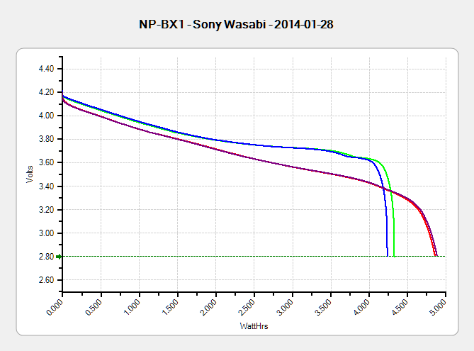
The discharge tests run at 250 mA, which is probably a bit low, as the HDR-AS30V camera can capture video for about two hours on a single battery. Given the Sony’s nominal 1.24 A·h (love that precision!) capacity and derating the Wasabi’s ambitious 1.6 A·h, two hours suggests a current around 500 mA would be more appropriate, but we’ll go with a lower current for now.
Oddly, the two Wasabi batteries (green & blue traces) outperform the Sony OEM battery (red and purple) in terms of voltage:
Sony NP-BX1 – OEM Wasabi – 2014-01-28
I can’t explain the small kink just before the big dropoff for both Wasabi batteries. Perhaps the protection circuitry behind the battery terminals has a slight peculiarity?
Looking at the total energy delivered, however:
Sony NP-BX1 – OEM Wasabi – Wh – 2014-01-28
The Sony battery says it’ll deliver 4.5 W·h and actually produces 4.8 W·h. The Wasabi batteries claim 5.7 W·h and don’t even come close at 4.25 W·h.
I cross-checked those results by importing the CSV data into a spreadsheet, computing the point-by-point power, finding the average, and then multiplying by the total test time in hours. Doing it a couple different ways says you can eyeball a reasonable value by multiplying the median voltage by the test current to get average wattage, then multiplying by the total test time to get W·h. That’s within a few percent, which is good enough for me.
The camera’s power supply undoubtedly has a low-voltage cutoff, but it’s a single-cell battery and they might just run it down around 2.8 V; in that case, the Sony batteries will last longer. If the voltage cutout is 3.5 V, similar to the Canon camera, then the Wasabi batteries win.
I don’t have enough experience with the camera or the batteries to predict anything based on actual use.