Ed Nisley's Blog: Shop notes, electronics, firmware, machinery, 3D printing, laser cuttery, and curiosities. Contents: 100% human thinking, 0% AI slop.
I’m pretty sure that chip at 1 o’clock happened while it was clamped in the vise between two cardboard sheets, but I haven’t a clue as how it got that much force. In any event, that shouldn’t affect the results very much, right up until it snaps in two.
Although the current will come from a (rectified) 120 VAC source, the winding will support only as much voltage as comes from the IR drop and inductive reactance, which shouldn’t be more than a fraction of a volt. Nevertheless, I wound the core with transformer tape:
FT82-43 toroid – wrapped
That’s 3M 4161-11 electrical tape (apparently out of production, but perhaps equivalent to 3M’s Super 10 tape) cut into half-foot lengths, slit to 100 mils, and wrapped ever so gently.
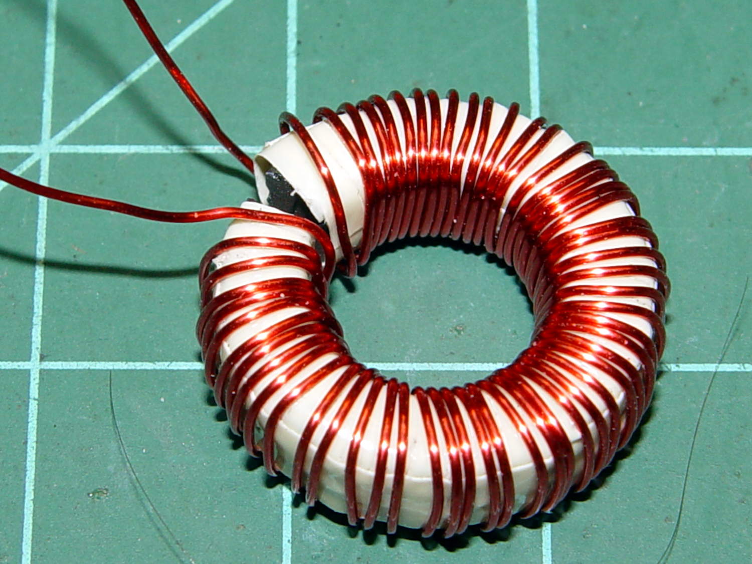
The thickest offering from the Big Box o’ Specialty Wire was 24 AWG, so that’s what I wound on it:
FT82-43 toroid – wound
That’s 56 turns, which should convert 2.2 A into 1000 G (enough to max out the Hall effect sensor) and is more in keeping with 24 AWG wire’s 3.5 A current rating.
The insulated core requires just under 1 inch/turn, so figure the length at 56 inch. The wire tables show 26.2 Ω/1000 ft, so the DC winding resistance should be 120 mΩ. My desk meter has 0.1 Ω resolution, which is exactly the difference between shorted probes and probes across the coil: close enough.
The inductance is 170 µH, so the inductive reactance at 120 Hz = 128 mΩ.
The audio quality was terrible, so I tried another bud with a foam windscreen over the hole and a hole punched in the middle of the double-sided white foam tape:
Earbud – foam over vent
The audio remained unintelligible, so I tried an upscale (but still cheap, because surplus) Koss earbud, first without blocking the vents and then with snippets of Kapton tape:
Koss earbud – tape over vent
The earphone has three slits on each side, but only the middle slit has a hole penetrating the case; it must be a stylin’ thing.
That sounded better, so I’ll roll with it. There’s supposed to be a foam cover over the housing, but those things always get grody and fall off; there’s not much point.
As nearly as I can tell, contemporary earbud designs optimize for volume (dBm/mV) and thumpin’ bass, all to the detriment of actual audio quality. Based on numerous samples over the years, there is zero correlation between price (admittedly, on the low end) and audio quality (admittedly, with my crappy hearing).
I own a pair of very nice (and thoroughly obsolete) Shure E2c sound-isolating ear beetles that sound great (even with my crappy hearing), but I’m unwilling to chop them up for the bike headset …
The motor winding resistance limits the peak current to about 200 V / 40 Ω = 5 A, in the absence of the transistor current limiter, and, if it gets above that, things have gone very, very wrong. Mostly, I expect currents under 1 A and it may be useful to reduce the full scale appropriately.
The cheap eBay “SS49” Hall effect sensors I’m using produce anywhere between 0.9 and 1.8 mV/G; I’ll use 1.4 mV/G, which is at least close to the original Honeywell spec. That allows a bit over ±1000 G around the sensor’s VCC/2 bias within its output voltage range (the original datasheet says minimum ±650 G), so I’ll use B = 1000 G as the maximum magnetic flux density. The overall calibration will be output voltage / input current and I’m not above doing a one-off calibration run and baking the constant into the firmware.
The effective mean path length turns out to be a useful value for a slit toroid:
effective MPL = (toroid MPL - air gap length) + (µ · air gap length)
The SS49 style sensor spec says they’re 1.6 mm thick, and the saw-cut gaps run a bit more, but 1.5 mm will be close enough for now.
The relation between all those values:
B = 0.4 π µ NI / (effective MPL)
Solving for NI:
NI = B · (eff MPL) / (0.4 π µ)
Solving for N:
N = B · (eff MPL) / (0.4 π µ I)
You always round up the result for N, because fractional turns aren’t a thing you can do with a toroid.
The saturation flux density seems to be measured at H = 10 Oe, but that applies to the intact toroids. The air gap dramatically reduces the effective µ, so you must apply a higher H to get the same B in the ferrite at saturation. At least, I think that’s the way it should work.
H = 0.4 π NI / (geometric MPL)
Then:
FT50-61: H = 58 Oe
FT82-43: H = 30 Oe
I’m surely missing some second-order effect that invalidates all those numbers.
Figuring the wire size for the windings:
FT50:
ID = 0.281 inch
Circumference = 0.882 inch
28 turns → wire OD = 0.882/28 = 31 mil
20 AWG without insulation
FT82:
ID = 0.520 inch
Circumference = 1.63 inch
25 turns → wire OD = 1.63/25 = 65 mil
14 AWG without insulation
Of course, the wire needs insulation, but, even so, the FT82 allows a more rational wire size.
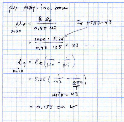
Page 4.12 of the writeup from Magnetics Inc has equations and a helpful chart. They suggest water cooling a diamond-bonded wheel during the slitting operation; my slapdash technique worked only because I took candy-ass cuts.
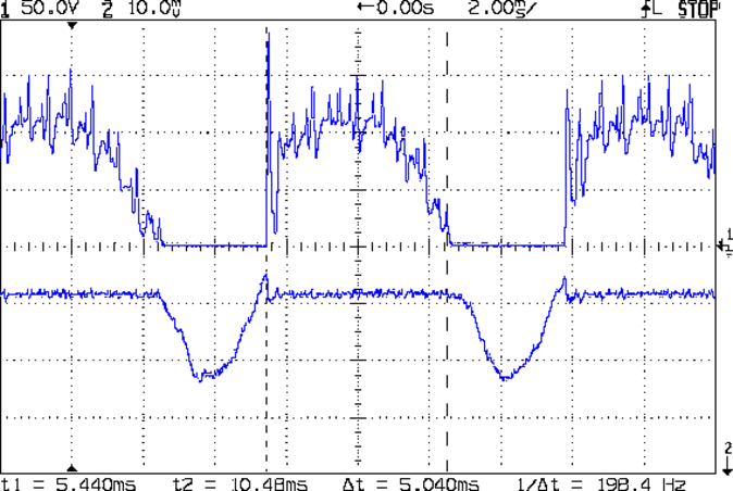
The motor current (200 mA/div) never goes to zero, but the ET227 collector voltage hits zero as the transistor saturates: the motor winding soaks up all the available line voltage and the transistor dissipation drops close to zero. The datasheet suggests VCE(sat) < 0.1 V for IC < 5 A, albeit with IB = 30 A (!).
The ET227 base drive was 77 mA, measured on a better meter than the low-resolution one in the power supply, and the transistor gain works out to 8 = 620 mA / 77 mA along those flat tops.
Eyeballometrically speaking, the dissipation averages 50 W = 90 V x 620 mA during those spiky sections where the transistor must absorb the difference between the line voltage and the motor voltage. The cursors say that takes 5 ms of the 8.3 ms period of the 120 Hz full wave rectified power, so the duty cycle is 42% and the average average dissipation works out to 20 W. That’s still enough to warm up that big heatsink; the motor driver will need a thermal sensor and a quiet fan.
That commutation noise looks pretty scary, doesn’t it?
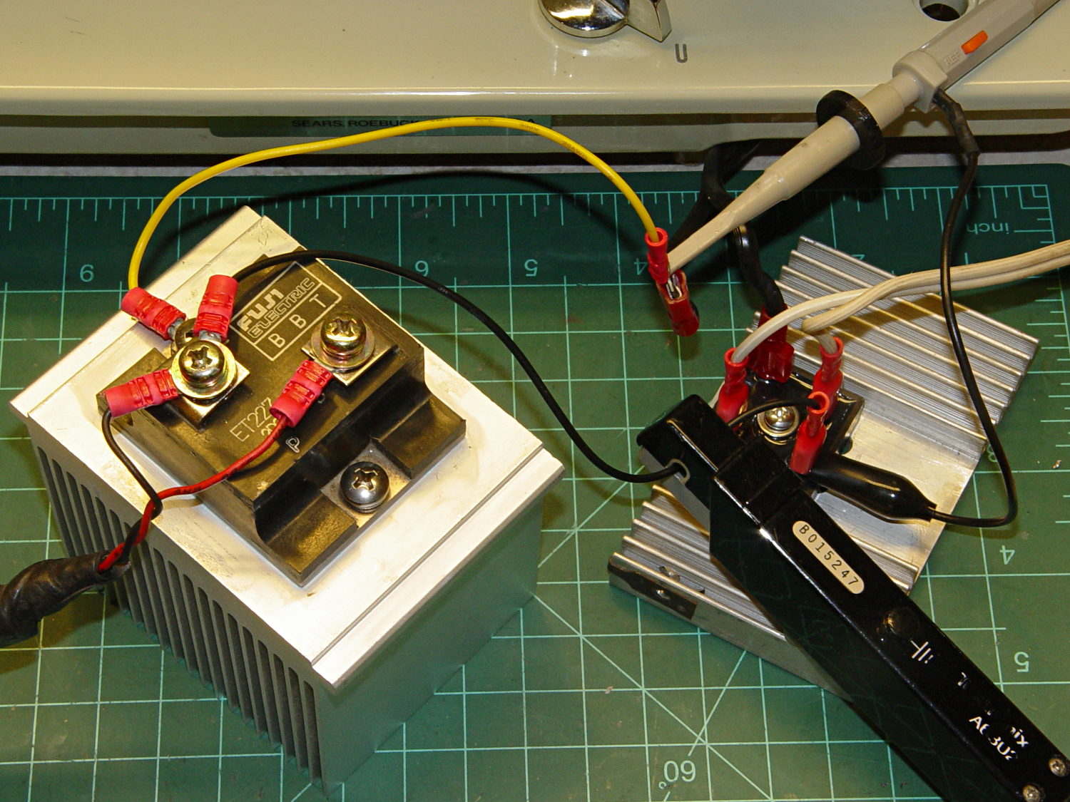
The test setup:
Kenmore 158 – AC motor FW ET227 drive – test setup
The bridge rectifier doesn’t really need a heatsink, but it looked better for a Circuit Cellar picture…
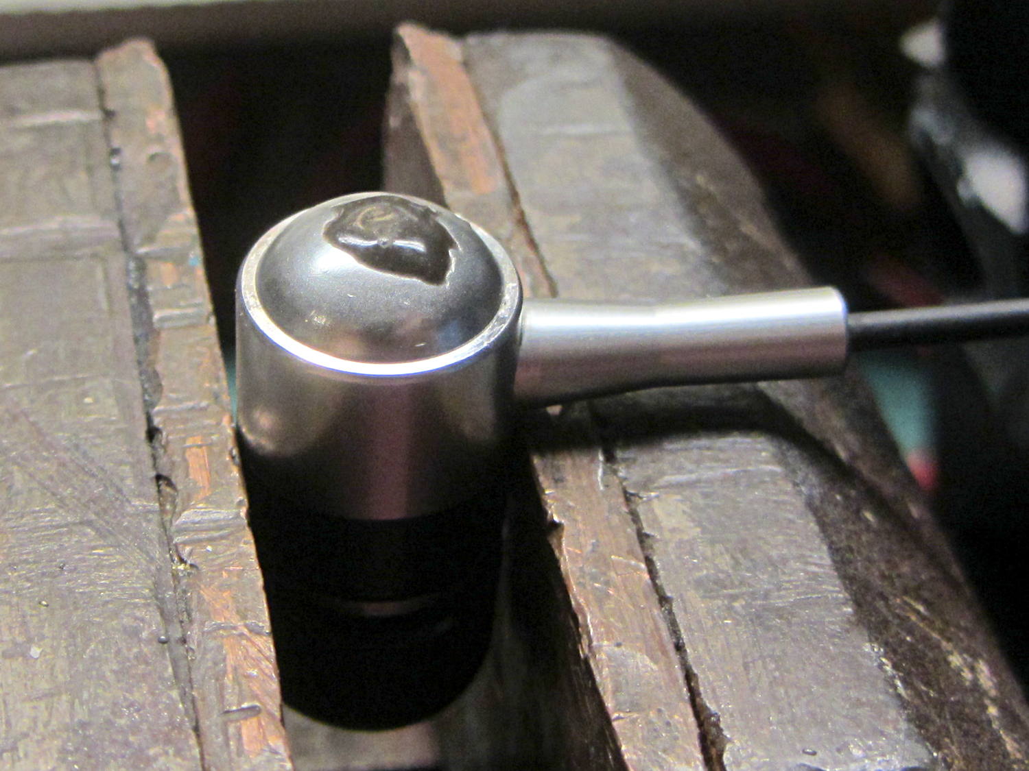
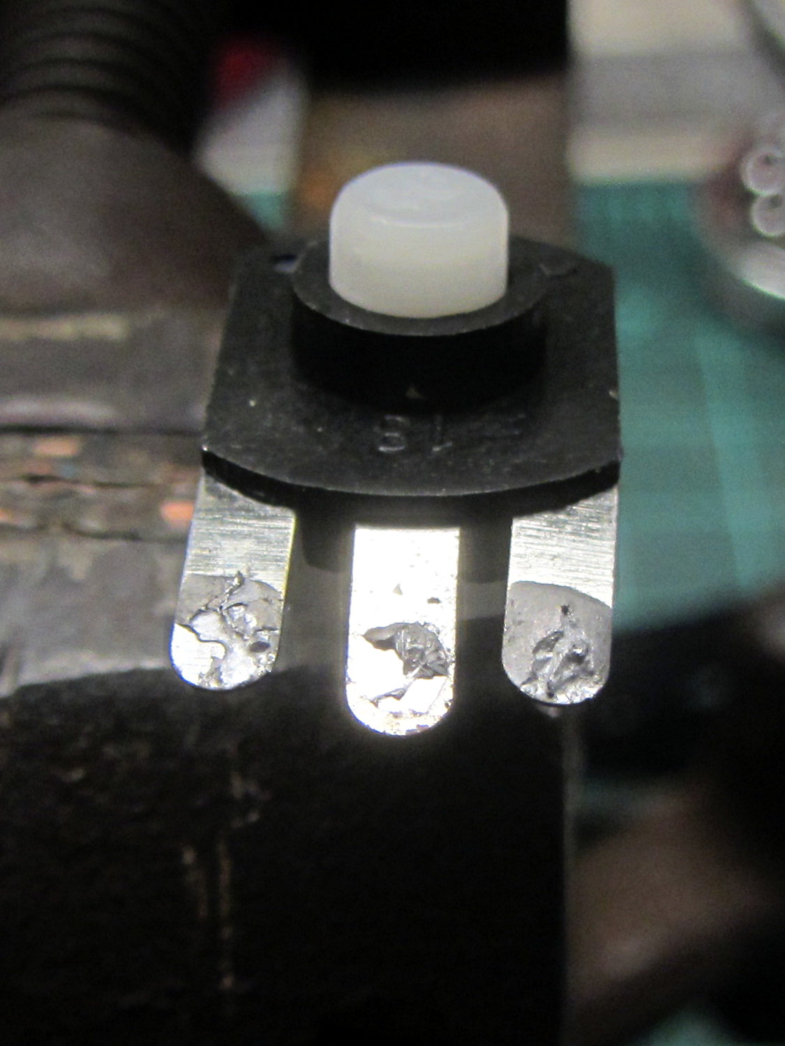
A four-click rotary pushbutton switch actuates the three functions (plus “off”) in sequence:
Flashlight switch – internal wiring
All three lights became intermittent, which suggested a poor return connection at the far end of the battery. The case is, of course, aluminum, with coarse-cut threads that grate as you tighten the parts. I cleaned the crud out of the threads, anointed them with Ox-Gard compound, and discovered that the laser and UV LEDs were still flaky.
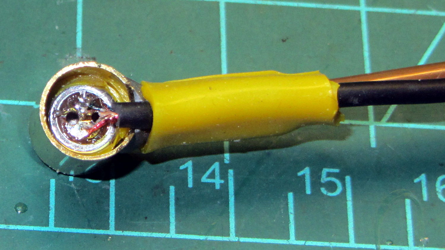
Taking the thing apart and unsoldering the switch connections revealed the problem:
Flashlight switch – bad solder joints
Yup, two lousy solder joints. They’re not exactly cold solder joints, because there’s not really a joint there to begin with; the switch tabs never got hot enough to bond with the molten solder before it cooled.
A dab of flux and touch from a hot soldering iron solved that problem.
Assemble in reverse order and it works better than it ever did before!
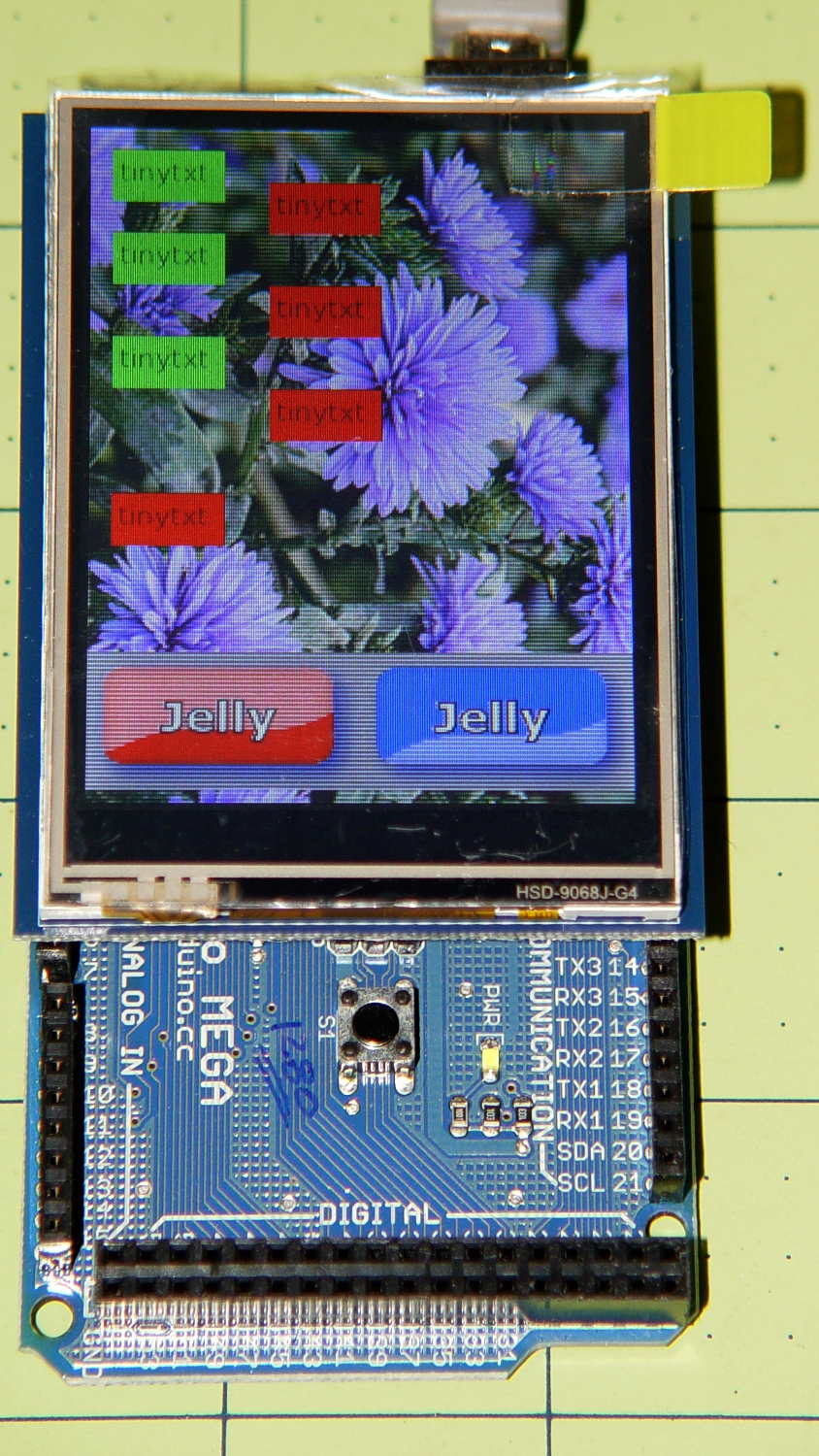
The Adafruit 2.8 inch TFT Touch Shield for Arduino v2 seems just about ideal for a small control panel, such as one might use with a modified sewing machine. All you need is a few on-screen buttons, a few status display, and a bit of Arduino love: what more could one ask?
So I gimmicked up some small buttons with GIMP, made two large buttons with ImageMagick, and lashed together some Arduino code based on the Adafruit demo:
Adafruit TFT display – timing demo
The picture doesn’t do justice to the display: it’s a nice piece of hardware that produces a crisp image. The moire patterns come from the interaction of TFT display pixels / camera pixels / image resizing.
It’s not obvious from the Adafruit description, but the display is inherently portrait-mode as shown. The (0,0) origin lies in the upper left corner, just over the DC power jack, and screen buffer updates proceed left-to-right, top-to-bottom from there.
The gotcha: even with the Arduino Mega’s hardware SPI, writing the full display requires nearly 4 seconds. Yeah, slow-scan TV in action. Writing the screen with a solid color requires several seconds.
After commenting out the serial tracing instructions from the Adafruit demo and tweaking a few other things, these timings apply:
-------------
Writing background
Elapsed: 3687
Writing six buttons
Elapsed: 529
Overwriting six buttons
Elapsed: 531
Rewriting buttons 10 times
Elapsed: 1767
Overwriting 2 large buttons
Elapsed: 1718
The button images come from BMP files on a MicroSD card and 8 KB of RAM won’t suffice for even a small button. Instead, the transfer loop buffers 20 pixels = 60 bytes from the card, writes them to the display, and iterates until it’s done.
Trust me on this: watching the buttons gradually change is depressing.
Yes, it could work as a control panel for the sewing machine, but it doesn’t have nearly the pep we’ve come to expect from touch-screen gadgetry. On the other paw, Arduinos are 8-bit microcontrollers teleported from the mid-90s, when crappy 20×4 LCD panels were pretty much as good as it got.
The SPI hardware clock runs at half the oscillator frequency = 16 MHz/2 = 8 MHz = 125 ns/bit. Clocking a single byte thus requires 1 µs; even allowing that each pixel = 3 bytes = 6 SPI operations, there’s a lot of software overhead ripe for the chopping block. I’d be sorely tempted to write a pair of unrolled loops that read 20 pixels and write 20 pixels with little more than a pointer increment & status spin between successive SPI transfers.
It’ll make hotshot C++ programmers flinch, but splicing all that into a single routine, throwing out all the clipping and error checking, and just getting it done might push the times down around 20 µs/pixel. Admittedly, that’s barely twice as fast, but should be less depressing.
However, even with all that effort, the time required to update the screen will clobber the motor control. You can’t devote a big fraction of a second to rewriting a button at the same time you’re monitoring the pedal position, measuring the motor speed, and updating the control voltage. That’s the same problem that makes Arduino microcontrollers inadequate for contemporary 3D printers: beyond a certain point, the hardware is fighting your efforts, not helping you get things done.
A reasonable workaround: no screen updates while the motor turns, because you shouldn’t have any hands free while you’re sewing.
The Arduino source code, hacked from the Adafruit demo:
// 2.8 inch TFT display exercise
// Crudely hacked from Adafruit demo code: spitftbitmap.ino
// 2014-07-03 Ed Nisley KE4ZNU

/***************************************************
  This is our Bitmap drawing example for the Adafruit ILI9341 Breakout and Shield
  ----> http://www.adafruit.com/products/1651

  Check out the links above for our tutorials and wiring diagrams
  These displays use SPI to communicate, 4 or 5 pins are required to
  interface (RST is optional)
  Adafruit invests time and resources providing this open source code,
  please support Adafruit and open-source hardware by purchasing
  products from Adafruit!

  Written by Limor Fried/Ladyada for Adafruit Industries.
  MIT license, all text above must be included in any redistribution
 ****************************************************/

#include <Adafruit_GFX.h>    // Core graphics library
#include "Adafruit_ILI9341.h" // Hardware-specific library
#include <SPI.h>
#include <SD.h>

#define TFT_DC 9
#define TFT_CS 10
Adafruit_ILI9341 tft = Adafruit_ILI9341(TFT_CS, TFT_DC);

#define SD_CS 4

unsigned long MillisNow, MillisThen;

void setup(void) {
  Serial.begin(115200);

  tft.begin();
  tft.fillScreen(ILI9341_BLACK);

  Serial.print(F("Initializing SD card..."));
  if (!SD.begin(SD_CS)) {
    Serial.println(F("failed!"));
  }
  Serial.println(F("OK!"));

}

void loop() {
  Serial.println(F("--------------"));
  Serial.println(F("Writing background"));
  MillisThen = millis();

  bmpDraw("Test1.bmp", 0, 0);

  MillisNow = millis();
  Serial.print(F("" Elapsed: ""));
  Serial.println(MillisNow - MillisThen);

  Serial.println(F("Writing 6 small buttons"));
  MillisThen = millis();

  bmpDraw("Red50x25.bmp",10,10);
  bmpDraw("Red50x25.bmp",10,50);
  bmpDraw("Red50x25.bmp",10,100);

  bmpDraw("Grn50x25.bmp",80,25);
  bmpDraw("Grn50x25.bmp",80,75);
  bmpDraw("Grn50x25.bmp",80,125);

  MillisNow = millis();
  Serial.print(F("" Elapsed: ""));
  Serial.println(MillisNow - MillisThen);

  Serial.println(F("Overwriting 6 small buttons"));
  MillisThen = millis();

  bmpDraw("Grn50x25.bmp",10,10);
  bmpDraw("Grn50x25.bmp",10,50);
  bmpDraw("Grn50x25.bmp",10,100);

  bmpDraw("Red50x25.bmp",80,25);
  bmpDraw("Red50x25.bmp",80,75);
  bmpDraw("Red50x25.bmp",80,125);

  MillisNow = millis();
  Serial.print(F("" Elapsed: ""));
  Serial.println(MillisNow - MillisThen);

  Serial.println(F("Writing small button 10x2 times"));
  MillisThen = millis();

  for (byte i=0; i<10; i++) {
    bmpDraw("Grn50x25.bmp",10,175);
    bmpDraw("Red50x25.bmp",10,175);
  }

  MillisNow = millis();
  Serial.print(F("" Elapsed: ""));
  Serial.println(MillisNow - MillisThen);

  Serial.println(F("Overwriting 2 large buttons"));
  MillisThen = millis();

  bmpDraw("GelDn.bmp",0,250);
  bmpDraw("GelUp.bmp",0,250);

  bmpDraw("GelUp.bmp",120,250);
  bmpDraw("GelDn.bmp",120,250);

  MillisNow = millis();
  Serial.print(F("" Elapsed: ""));
  Serial.println(MillisNow - MillisThen);

}

// This function opens a Windows Bitmap (BMP) file and
// displays it at the given coordinates.  It's sped up
// by reading many pixels worth of data at a time
// (rather than pixel by pixel).  Increasing the buffer
// size takes more of the Arduino's precious RAM but
// makes loading a little faster.  20 pixels seems a
// good balance.

#define BUFFPIXEL 20

void bmpDraw(char *filename, uint8_t x, uint16_t y) {

  File     bmpFile;
  int      bmpWidth, bmpHeight;   // W+H in pixels
  uint8_t  bmpDepth;              // Bit depth (currently must be 24)
  uint32_t bmpImageoffset;        // Start of image data in file
  uint32_t rowSize;               // Not always = bmpWidth; may have padding
  uint8_t  sdbuffer[3*BUFFPIXEL]; // pixel buffer (R+G+B per pixel)
  uint8_t  buffidx = sizeof(sdbuffer); // Current position in sdbuffer
  boolean  goodBmp = false;       // Set to true on valid header parse
  boolean  flip    = true;        // BMP is stored bottom-to-top
  int      w, h, row, col;
  uint8_t  r, g, b;
  uint32_t pos = 0, startTime = millis();

  if((x >= tft.width()) || (y >= tft.height())) return;

//  Serial.println();
//  Serial.print(F("Loading image '"));
//  Serial.print(filename);
//  Serial.println('\'');

  // Open requested file on SD card
  if ((bmpFile = SD.open(filename)) == NULL) {
//    Serial.print(F("File not found"));
    return;
  }

  // Parse BMP header
  if(read16(bmpFile) == 0x4D42) { // BMP signature
//    Serial.print(F("File size: "));
//	Serial.println(read32(bmpFile));
	read32(bmpFile);
    (void)read32(bmpFile); // Read & ignore creator bytes
    bmpImageoffset = read32(bmpFile); // Start of image data
//    Serial.print(F("Image Offset: ")); Serial.println(bmpImageoffset, DEC);
    // Read DIB header
//    Serial.print(F("Header size: "));
//	Serial.println(read32(bmpFile));
	read32(bmpFile);
    bmpWidth  = read32(bmpFile);
    bmpHeight = read32(bmpFile);
    if(read16(bmpFile) == 1) { // # planes -- must be '1'
      bmpDepth = read16(bmpFile); // bits per pixel
//      Serial.print(F("Bit Depth: ")); Serial.println(bmpDepth);
      if((bmpDepth == 24) && (read32(bmpFile) == 0)) { // 0 = uncompressed

        goodBmp = true; // Supported BMP format -- proceed!
//        Serial.print(F("Image size: "));
//        Serial.print(bmpWidth);
//        Serial.print('x');
//        Serial.println(bmpHeight);

        // BMP rows are padded (if needed) to 4-byte boundary
        rowSize = (bmpWidth * 3 + 3) & ~3;

        // If bmpHeight is negative, image is in top-down order.
        // This is not canon but has been observed in the wild.
        if(bmpHeight < 0) {
          bmpHeight = -bmpHeight;
          flip      = false;
        }

        // Crop area to be loaded
        w = bmpWidth;
        h = bmpHeight;
        if((x+w-1) >= tft.width())  w = tft.width()  - x;
        if((y+h-1) >= tft.height()) h = tft.height() - y;

        // Set TFT address window to clipped image bounds
        tft.setAddrWindow(x, y, x+w-1, y+h-1);

        for (row=0; row<h; row++) { // For each scanline...

          // Seek to start of scan line.  It might seem labor-
          // intensive to be doing this on every line, but this
          // method covers a lot of gritty details like cropping
          // and scanline padding.  Also, the seek only takes
          // place if the file position actually needs to change
          // (avoids a lot of cluster math in SD library).
          if(flip) // Bitmap is stored bottom-to-top order (normal BMP)
            pos = bmpImageoffset + (bmpHeight - 1 - row) * rowSize;
          else     // Bitmap is stored top-to-bottom
            pos = bmpImageoffset + row * rowSize;
          if(bmpFile.position() != pos) { // Need seek?
            bmpFile.seek(pos);
            buffidx = sizeof(sdbuffer); // Force buffer reload
          }

          for (col=0; col<w; col++) { // For each pixel...
            // Time to read more pixel data?
            if (buffidx >= sizeof(sdbuffer)) { // Indeed
              bmpFile.read(sdbuffer, sizeof(sdbuffer));
              buffidx = 0; // Set index to beginning
            }

            // Convert pixel from BMP to TFT format, push to display
            b = sdbuffer[buffidx++];
            g = sdbuffer[buffidx++];
            r = sdbuffer[buffidx++];
            tft.pushColor(tft.color565(r,g,b));
          } // end pixel
        } // end scanline
//        Serial.print(F("Loaded in "));
//        Serial.print(millis() - startTime);
//        Serial.println("" ms"");
      } // end goodBmp
    }
  }

  bmpFile.close();
  if(!goodBmp) Serial.println(F("BMP format not recognized."));
}

// These read 16- and 32-bit types from the SD card file.
// BMP data is stored little-endian, Arduino is little-endian too.
// May need to reverse subscript order if porting elsewhere.

uint16_t read16(File &f) {
  uint16_t result;
  ((uint8_t *)&result)[0] = f.read(); // LSB
  ((uint8_t *)&result)[1] = f.read(); // MSB
  return result;
}

uint32_t read32(File &f) {
  uint32_t result;
  ((uint8_t *)&result)[0] = f.read(); // LSB
  ((uint8_t *)&result)[1] = f.read();
  ((uint8_t *)&result)[2] = f.read();
  ((uint8_t *)&result)[3] = f.read(); // MSB
  return result;
}