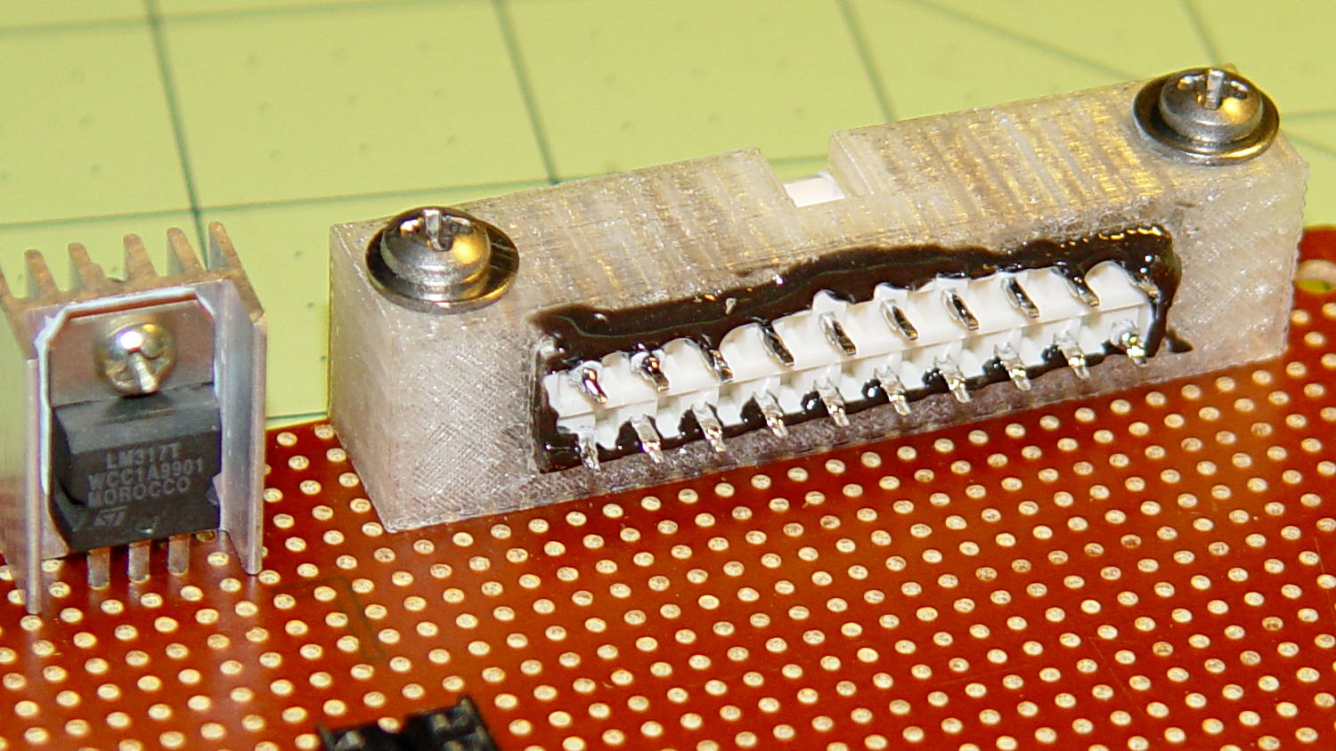
Given that the motor current amounts to maybe 3 A, absolute maximum, with a locked rotor, those skinny wires on the slit ferrite toroid won’t pose a problem:

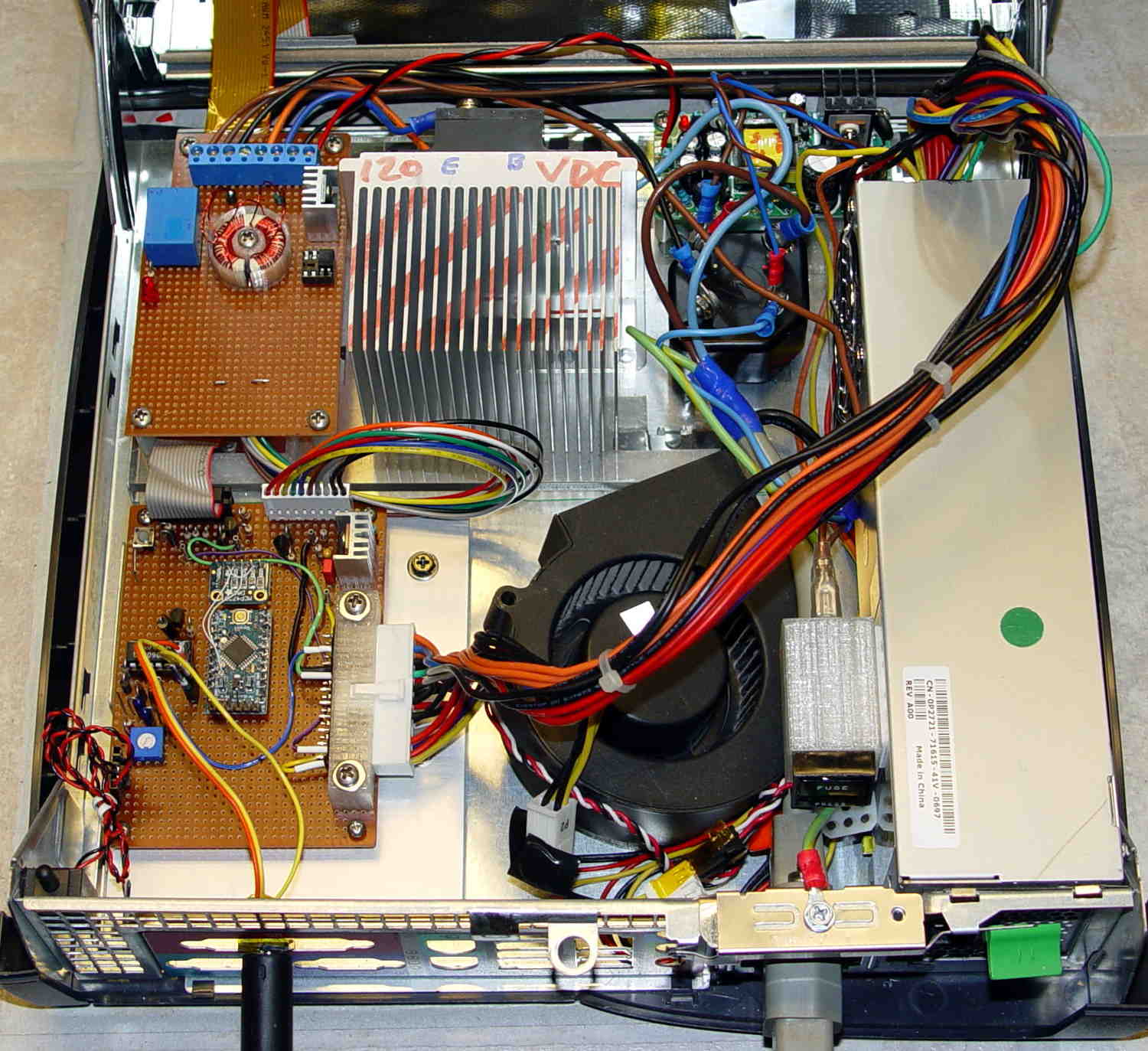
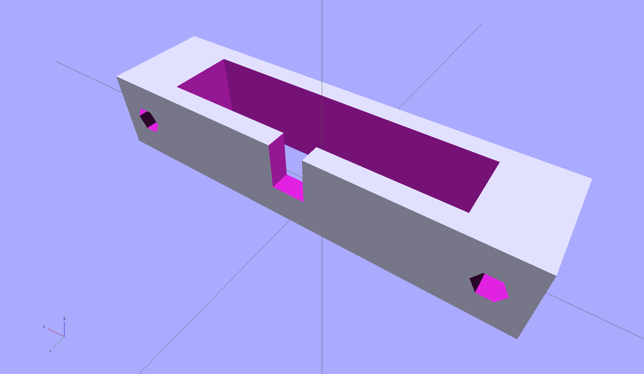
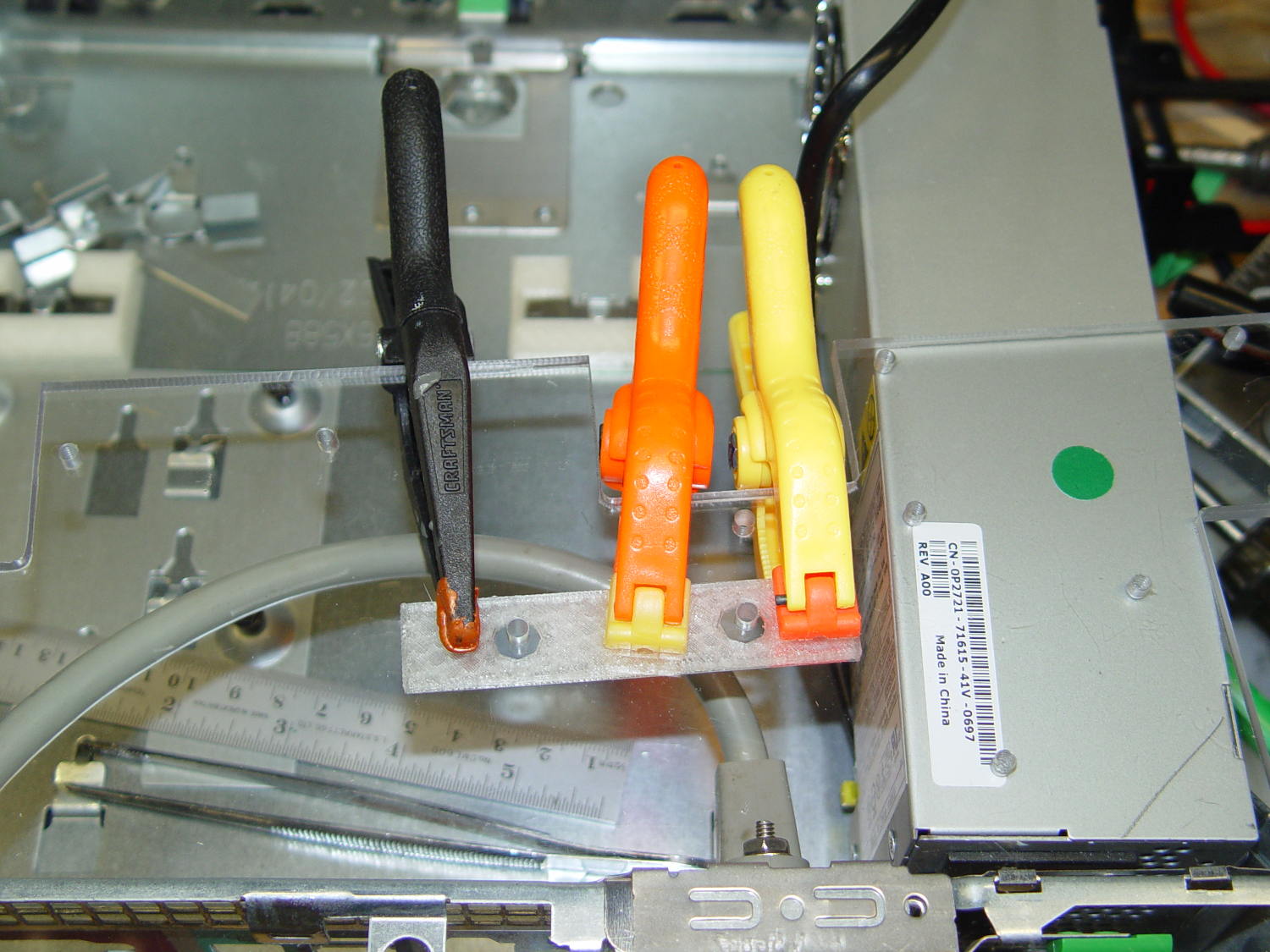
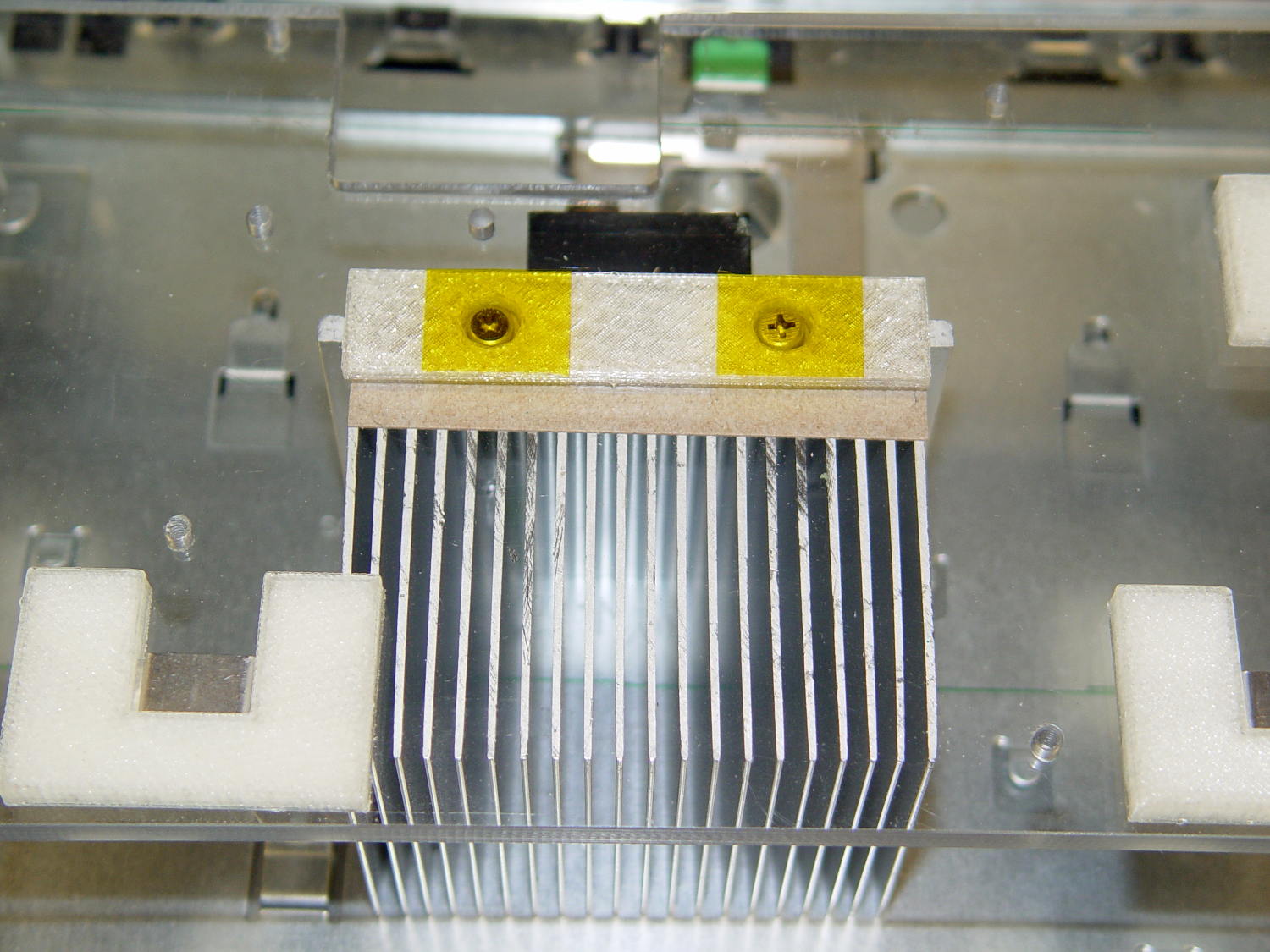
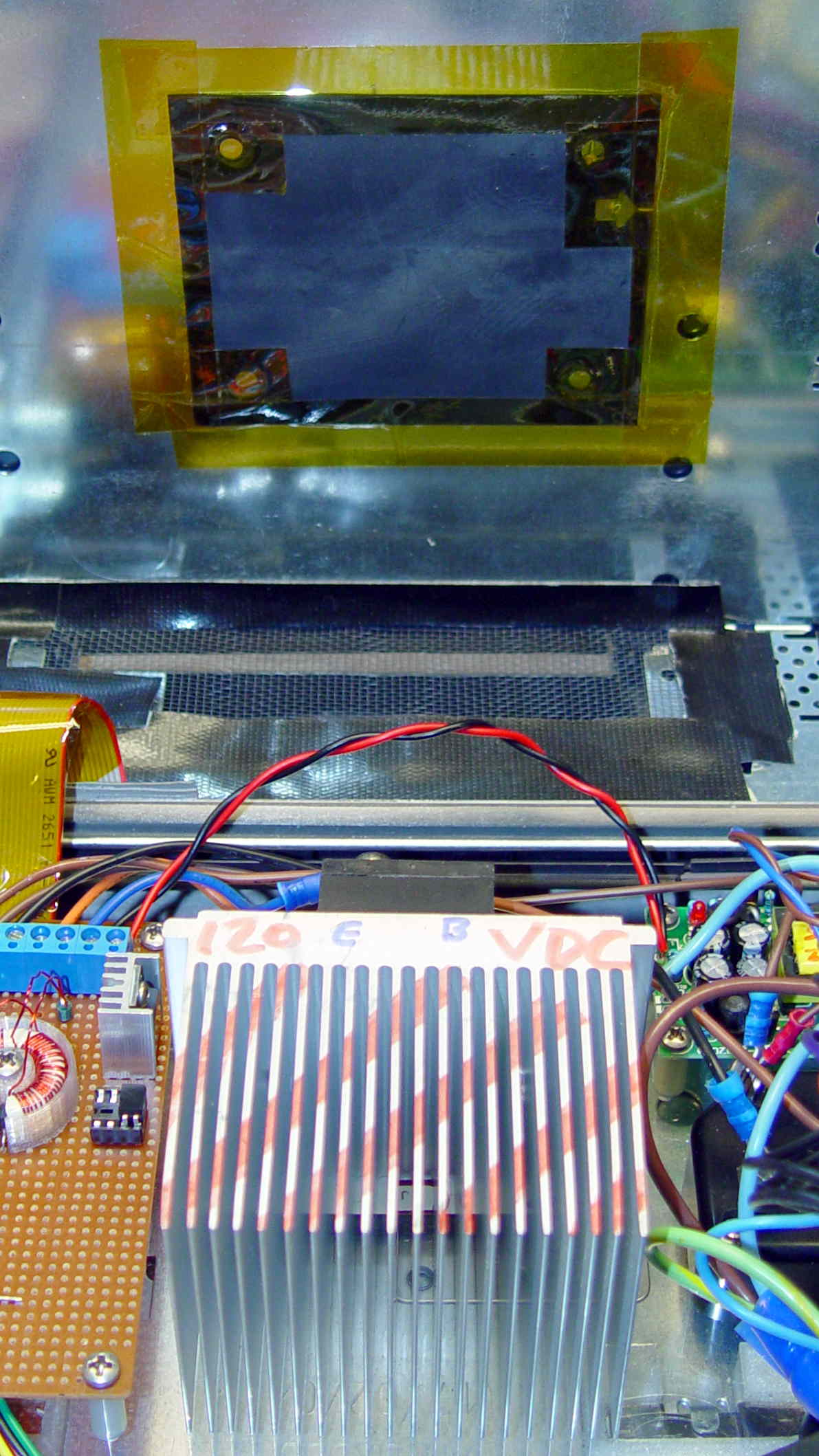
I really like how that 3D printed armor worked out, even if I still haven’t poured any goop around the windings to lock them down; they’re held in by raw faith and friction.
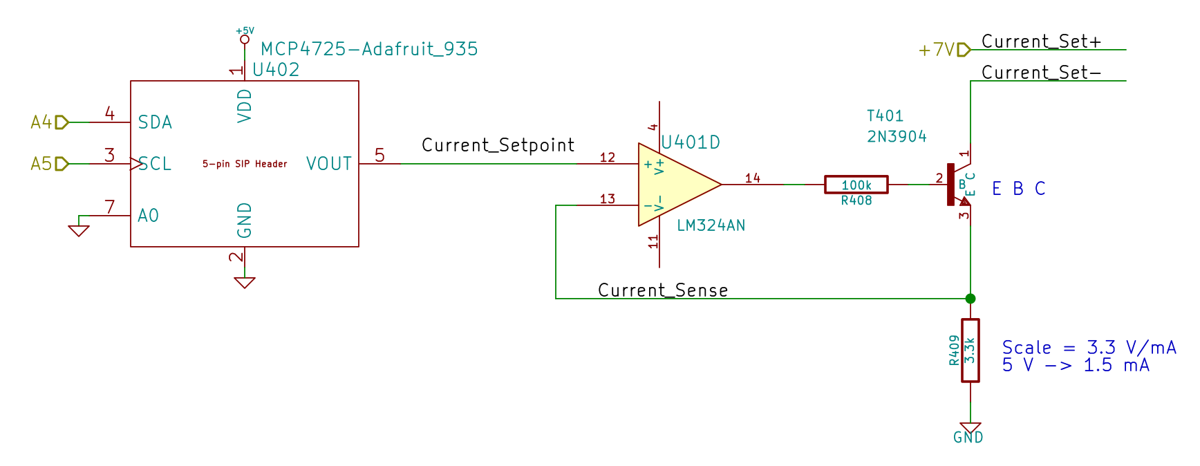
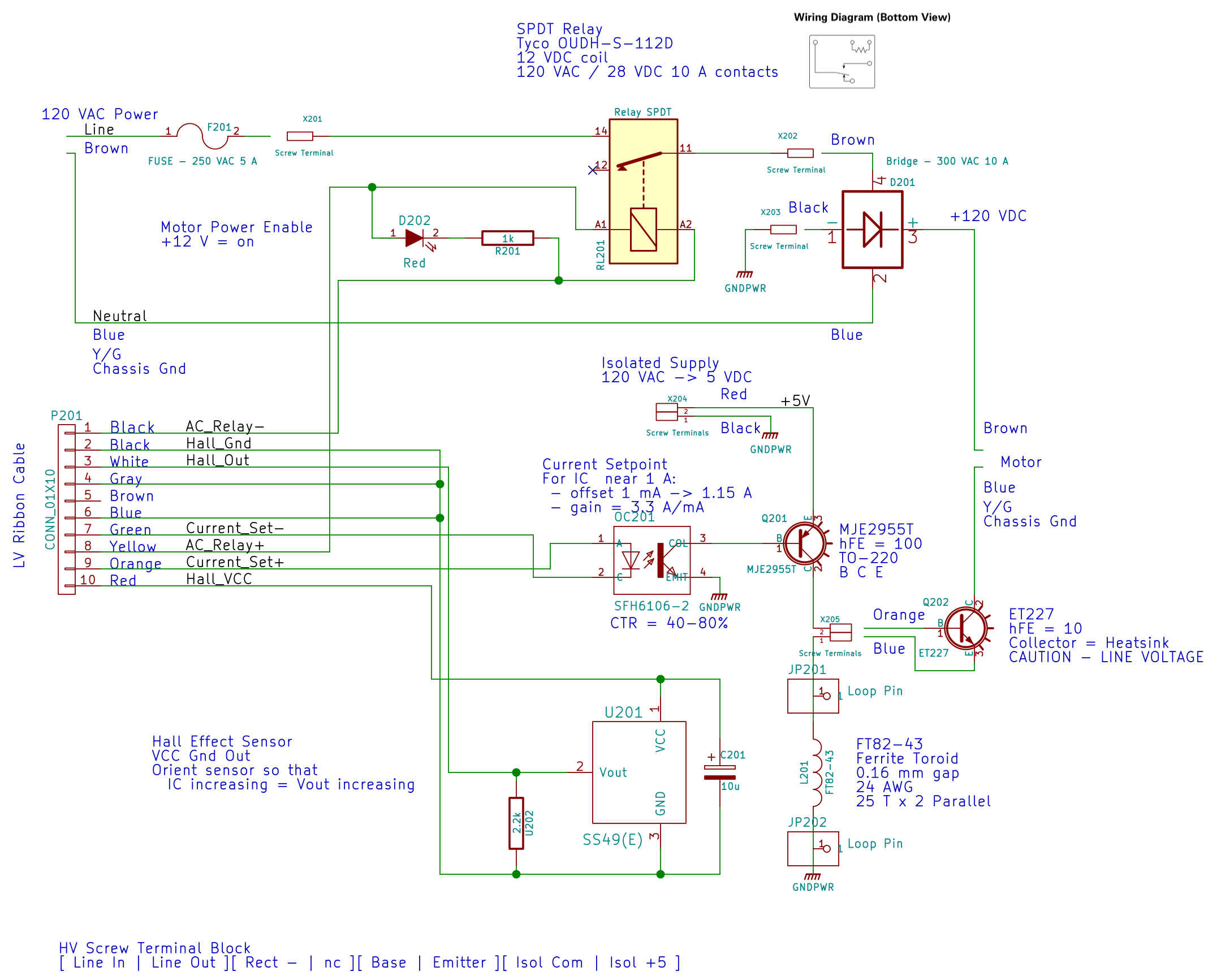
The current sense circuitry appears along the bottom of the AC Power Interface schematic:
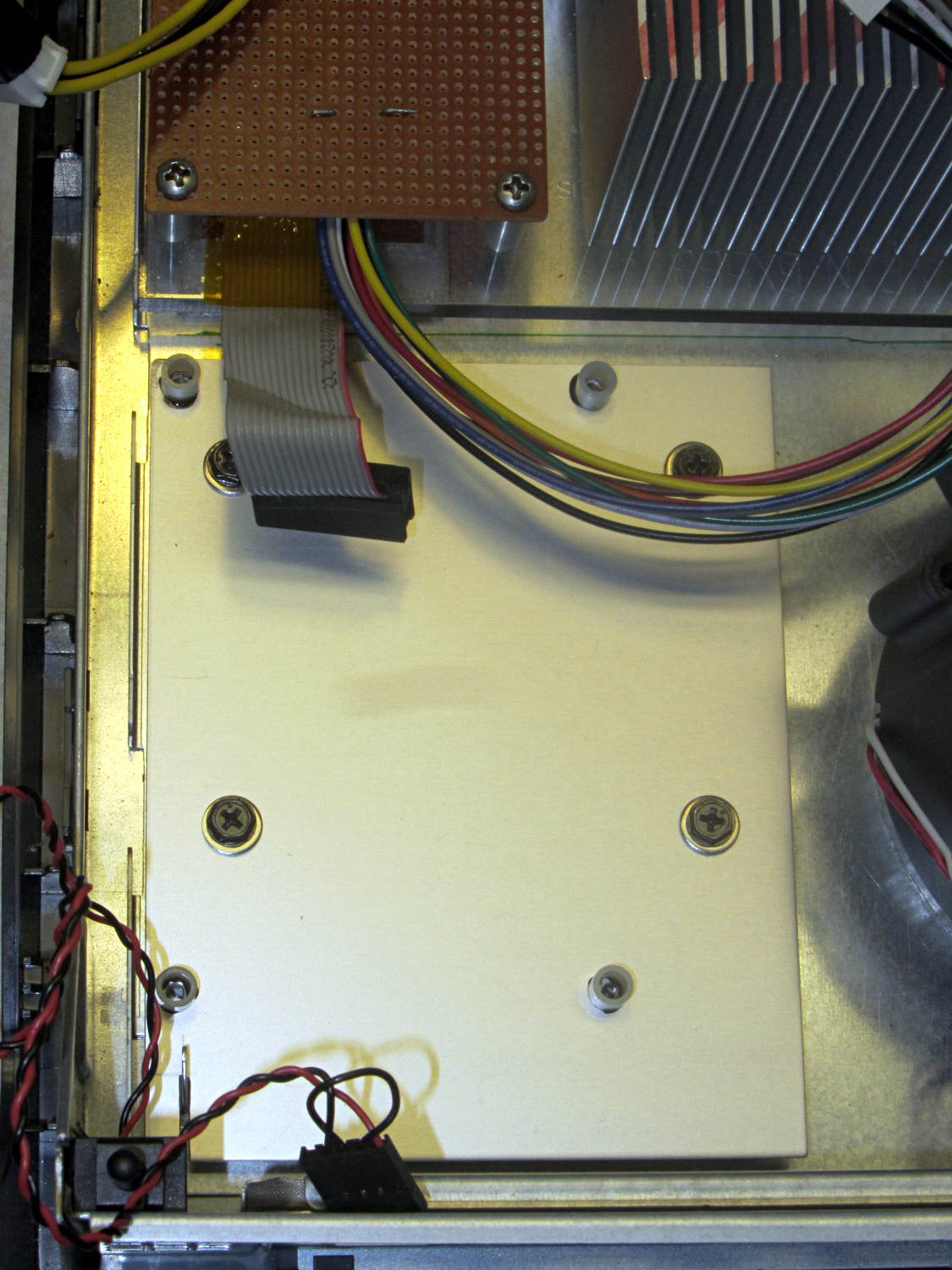
The differential amplifier lives on the Low Voltage Interface board, forming the clump of parts just in front of the LM324 op amp on the left:

Which has the usual handful of components required to get anything done in the analog realm:

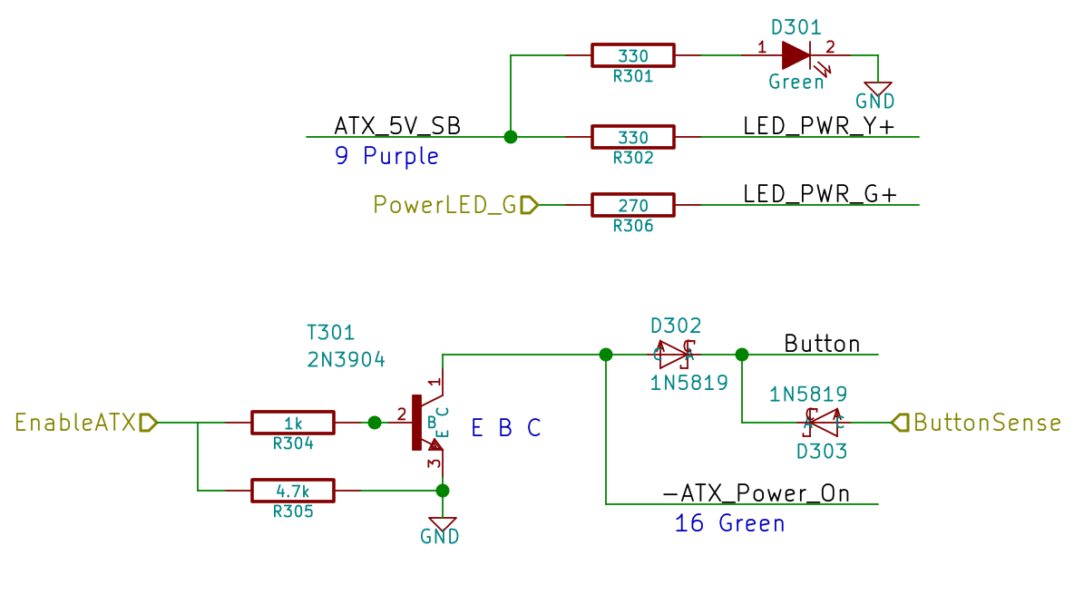
The power supplies come directly from the ATX connector. I’m ignoring the whole decoupling issue, because the supplies have essentially no load (and it’s all DC, anyway).
The trim pot sets the offset voltage to bring the Hall effect sensors’s VCC/2 offset down close to zero; the 100 mV figure is nominal, not actual, but should be a bit over 0 V to allow for a wee bit o’ drift. This time around, I’ll measure and subtract the actual offset, rather than (try to) auto-zero it.
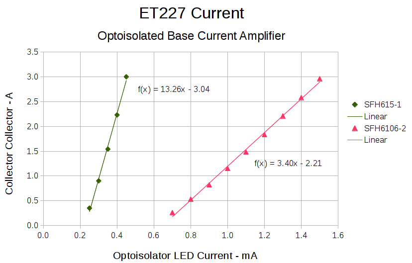
The voltage gain runs just under 3, set by 1% resistors from the heap. The overall gain works out to about 1.9 V/A or 525 mA/V, setting the high end at 5 V to a scant 2.6 A. Subject to actual calibration with more attention to detail, that’s close enough; we’re more interested in the around-an-amp range where the motor operates under nominal load.
The nose-to-tail Schottky diodes clamp the op amp output to avoid annoying the Arduino’s ADC input. It has protection circuitry, too, but there’s no point in stressing it.