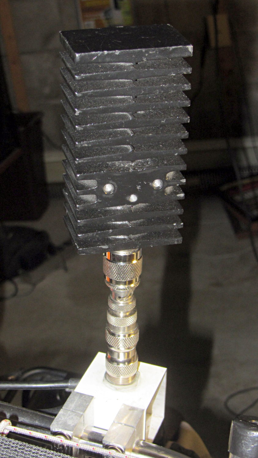
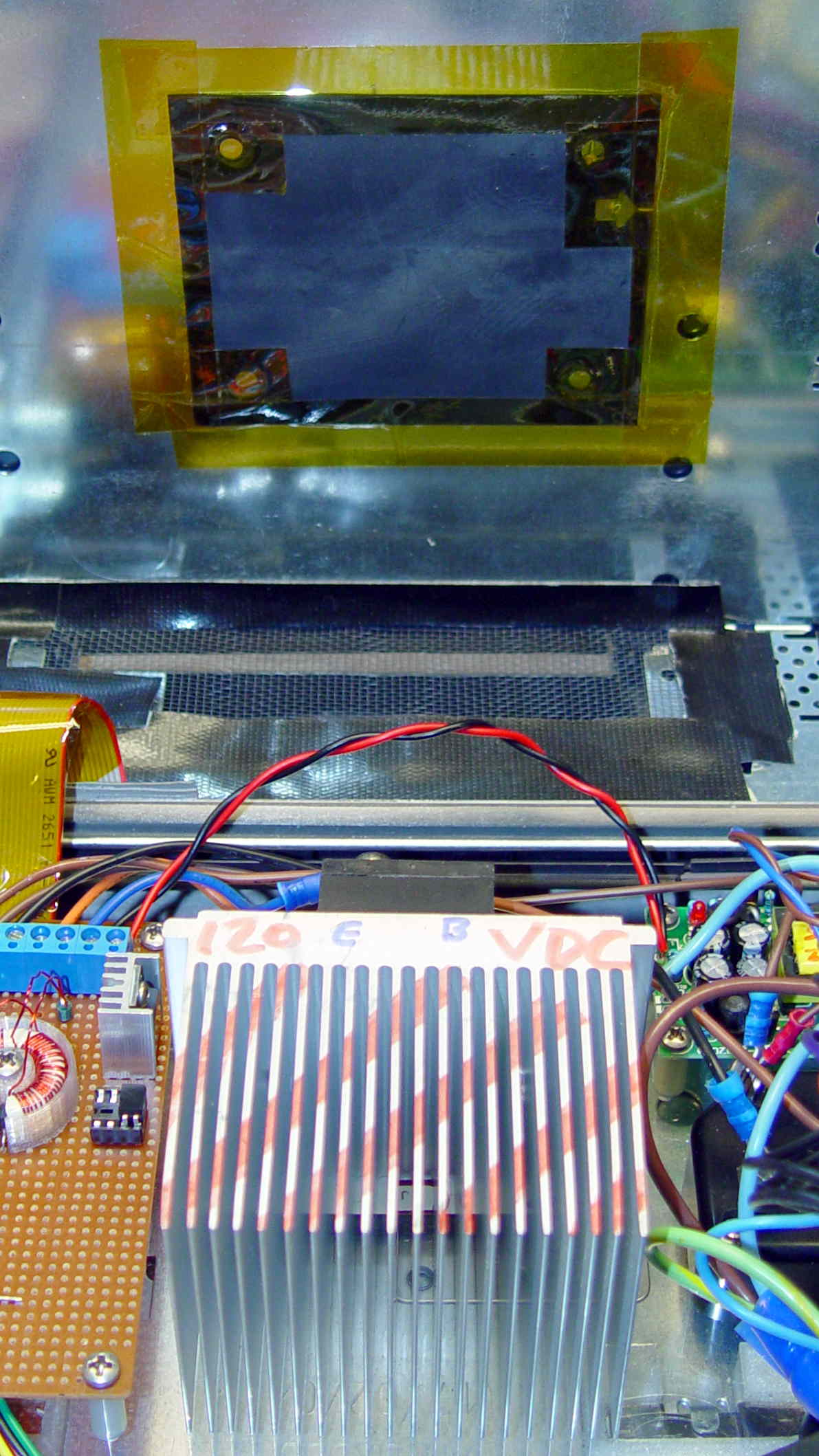
Back in the day, heatsinks like this sat atop Moah Powah Pentium CPUs:

I picked it because the hulking ET227 transistor fit neatly on its backside, it seemed capable of handling 30 to 50 W of power, and I have several of them in the Big Box o’ Heatsinks. No careful thermal analysis was involved…
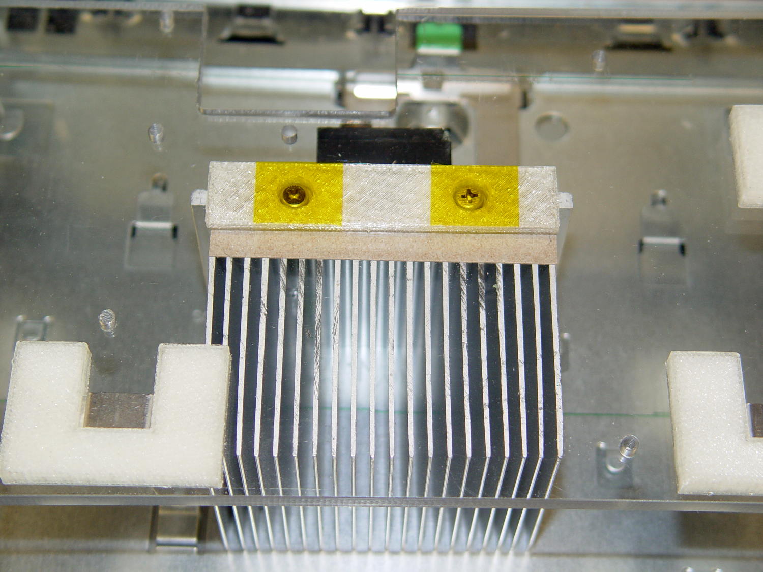
Mounting it on the polycarbonate sheet inside the repurposed GX270 case involved drilling & tapping a pair of 6-32 holes in one side:
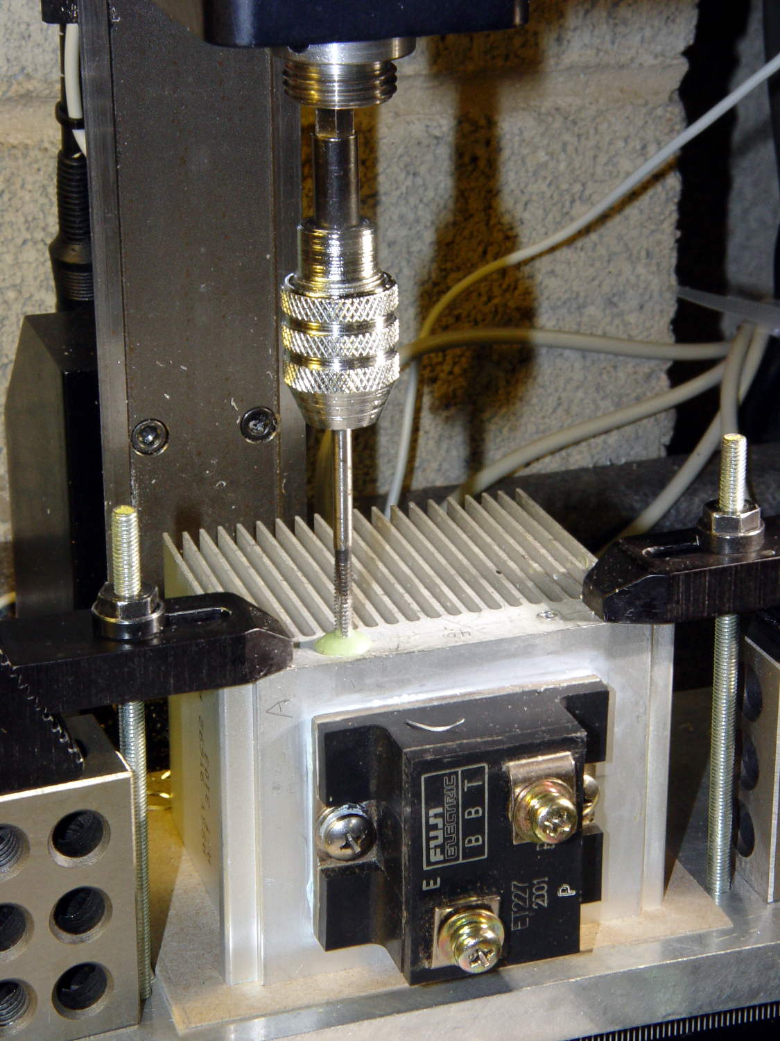
That’s not rigid tapping on a Sherline, it’s aligning a hand-turned tap in the spindle bore. Sorry.
And, yeah, you’re not supposed to leave the semiconductors mounted when you’re drilling the heatsink. I figure there’s nothing I can possibly do without using a hammer that will bother that transistor in the slightest. What, me worry?
The transistor collector runs at line voltage, which means the entire heatsink will pose a lethal shock hazard. I thought about isolating the collector and failed to come up with anything I’d trust to be both thermally conductive and electrically insulating over the long term; the screw heads must be isolated from the collector plate, too.
The screws stick out below the polycarbonate sheet, just above the grounded EMI shell lining the case, so I flattened them a bit:
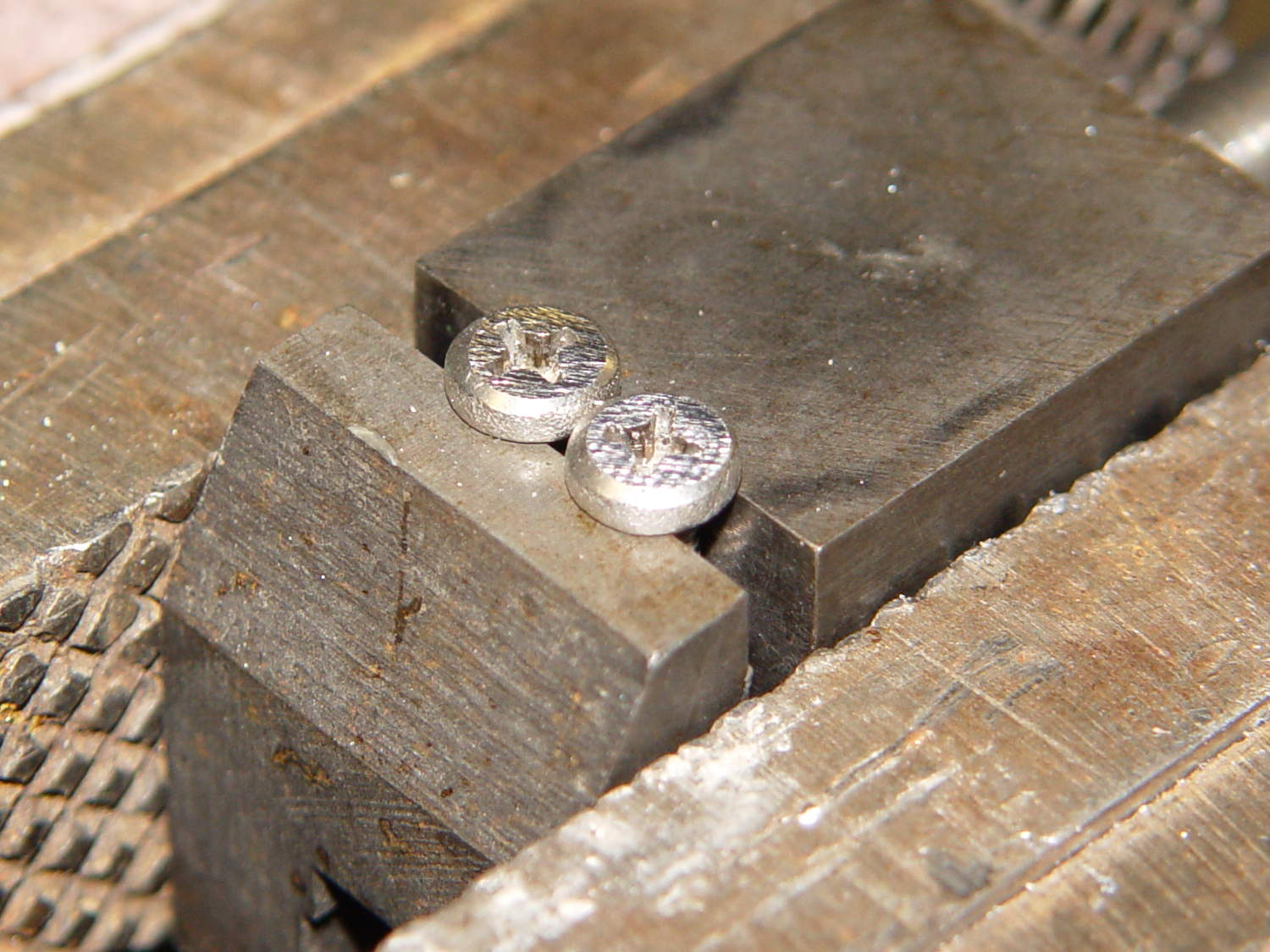
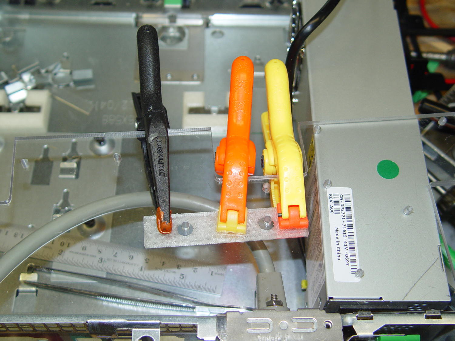
The simple rectangular strip to the rear of the chassis mounting clips is just slightly thicker than the screw heads, so they can’t possibly contact the case:

It gets glued to the underside of the nearly invisible sheet:
With Kapton tape over the heads, Just In Case:
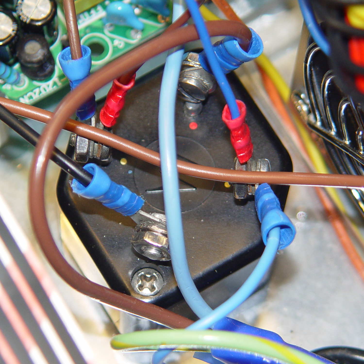
It makes a nice linear counterpoint to the jumble of AC interface wiring:

The insulating sheet on the case lid came from the bottom of the original GX270 system board, where I think it served much the same purpose. It’s surely not rated for AC line voltages, but the thought must count for something:
More of the parts are flying in formation…