Ed Nisley's Blog: Shop notes, electronics, firmware, machinery, 3D printing, laser cuttery, and curiosities. Contents: 100% human thinking, 0% AI slop.
Reducing the differential amp gain fits a higher current into the Arduino’s fixed 5 V ADC range:
Hall Sensor Differential Amp
Those are 1% resistors, chosen from the heap for being pretty close to what I needed. Given that it’s an LM324 op amp, we’re not talking instrumentation grade results here.
The same calibration run that produced the DAC plot gave these values:
Current Calibrate – ADC – 270k Hall 2.7k opto
The linear fit gives the actual current, as seen by the Tek probe, for a given ADC reading.
The trimpot controls the offset voltage at zero current; working backwards, ADC = 0 corresponds to 140 mV, a bit higher than the actual 90 mV. Close enough, at least for a linear fit to eyeballed data, sez I.
Working forward, the maximum ADC value of 1023 corresponds to 4 A, which should suffice.
Although small power diodes make fine flyback diodes for relays, the motor can draw several amps during the startup pulse, which will be a bit out of spec for the usual 1N4007-class diodes. Pressing an old 5 A / 200 V stud diode into service produces the ungainly black-and-blue lump eating the end of the green wire:
Motor flyback diode – installed
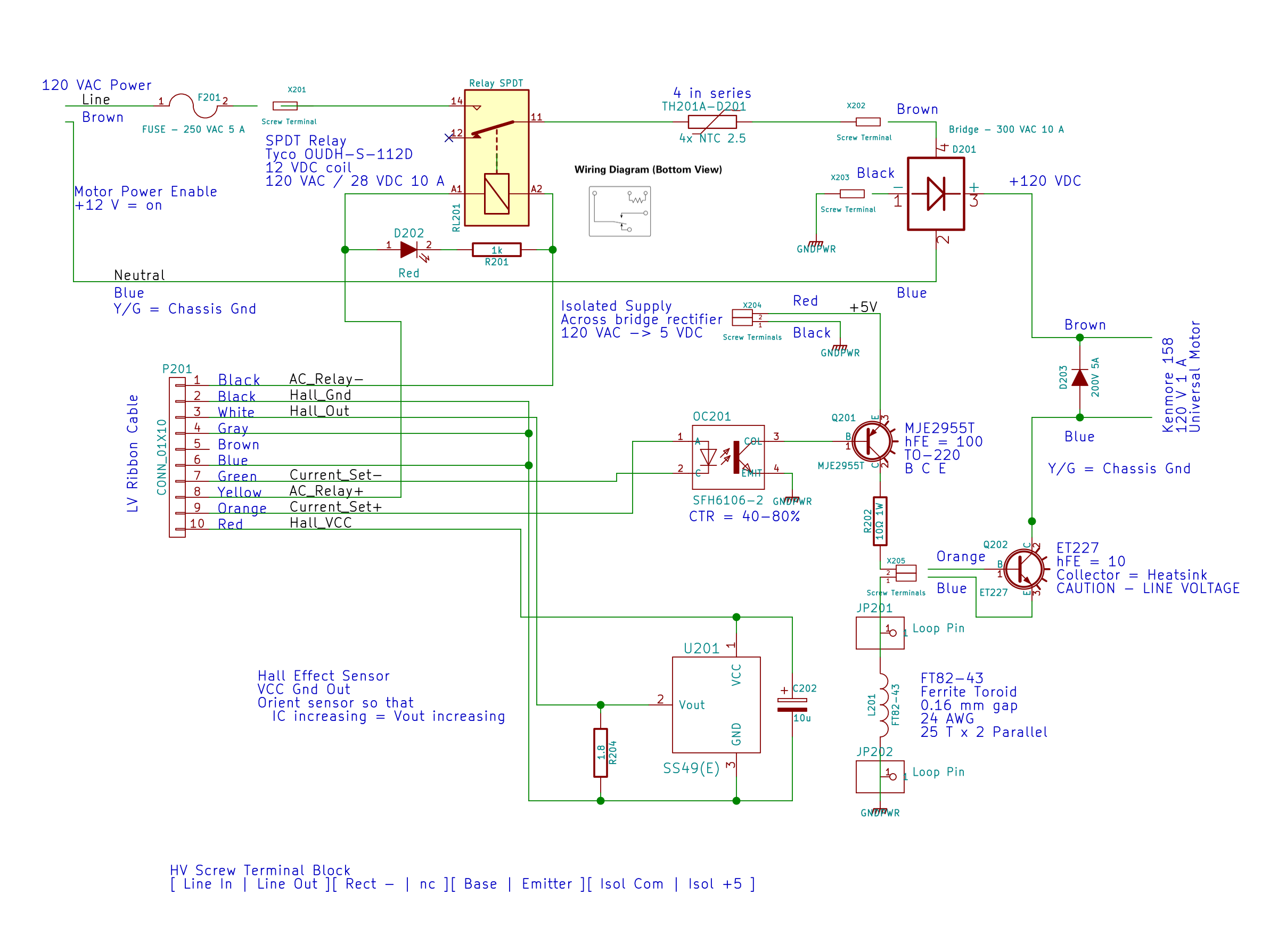
For completeness, here’s the entire AC line interface part of the schematic:
AC Power Interface
The diode’s 200 V limit should suffice, even for cold starts at high line peaks, but, when you build this with new parts, get something rated a bit higher, OK?
A Circuit Cellar reader sent me a lengthy note describing his approach to slow-motion AC motor drives, designed for an already ancient truck mounted radar antenna back in 1972-ish, that prompted me to try it his way.
The general idea is to pulse the motor at full current for half a power line cycle with an SCR (rather than a triac) at a variable pulse repetition rate: the high current pulse ensures that the motor will start turning and the variable repetition frequency determines the average speed. As he puts it, the motor will give off a distinct tick at very low speeds and the maximum speed will depend on how the motor reacts to half-wave drive.
Note that this is not the chopped-current approach to speed control: the SCR always begins conducting at the first positive-going 0 V crossing after the command and continues until the motor current drops to zero. There are no sharp edges generating high-pitched acoustic noise and EMI: silence is golden.
The existing speed control circuitry limits the peak current and assumes that the motor trundles along more-or-less steadily. That won’t be the case when it’s coasting between discontinuous current pulses.
When I first looked at running the motor on DC, these measurements showed the expected relationship:
Kenmore Model 158 AC Motor on DC – Loaded and Unloaded RPM vs Voltage
Eyeballometrically, the slowest useful speed will be 2 stitch/s = 120 shaft RPM = 1300 motor RPM. At that speed, under minimal load, the motor runs on about 20 V and draws 550 mA. At that current, the 40 Ω winding drops 22 V, which we’ll define as “about 20 V” for this discussion, so the back EMF amounts to pretty nearly zilch.
That’s what you’d expect for the fraction of a second while the motor comes up to full speed, but in this case it never reaches full speed, so the motor current during the pulses will be limited only by the winding resistance. At the 200 V peak I’ve been using for the high-line condition, that’s about 5 A peak, although I’d expect 4 A to be more typical.
So, in order to make this work:
the optocoupler driving the base needs more current
the differential amp from the Hall effect sensor needs less gain
Given the ease with which I’ve pushed the hulking ET227 transistor out of its SOA, the motor definitely needs a flyback diode to direct the winding current away from the collector as the transistor shut off at the end of the pulse. Because it’s running from full-wave rectified AC, the winding current never drops to zero: there will definitely be enough current to wreck the transistor.
The firmware needs reworking to produce discrete pulses at a regular pace, rather than slowly adjusting the current over time, but that’s a simple matter of software…
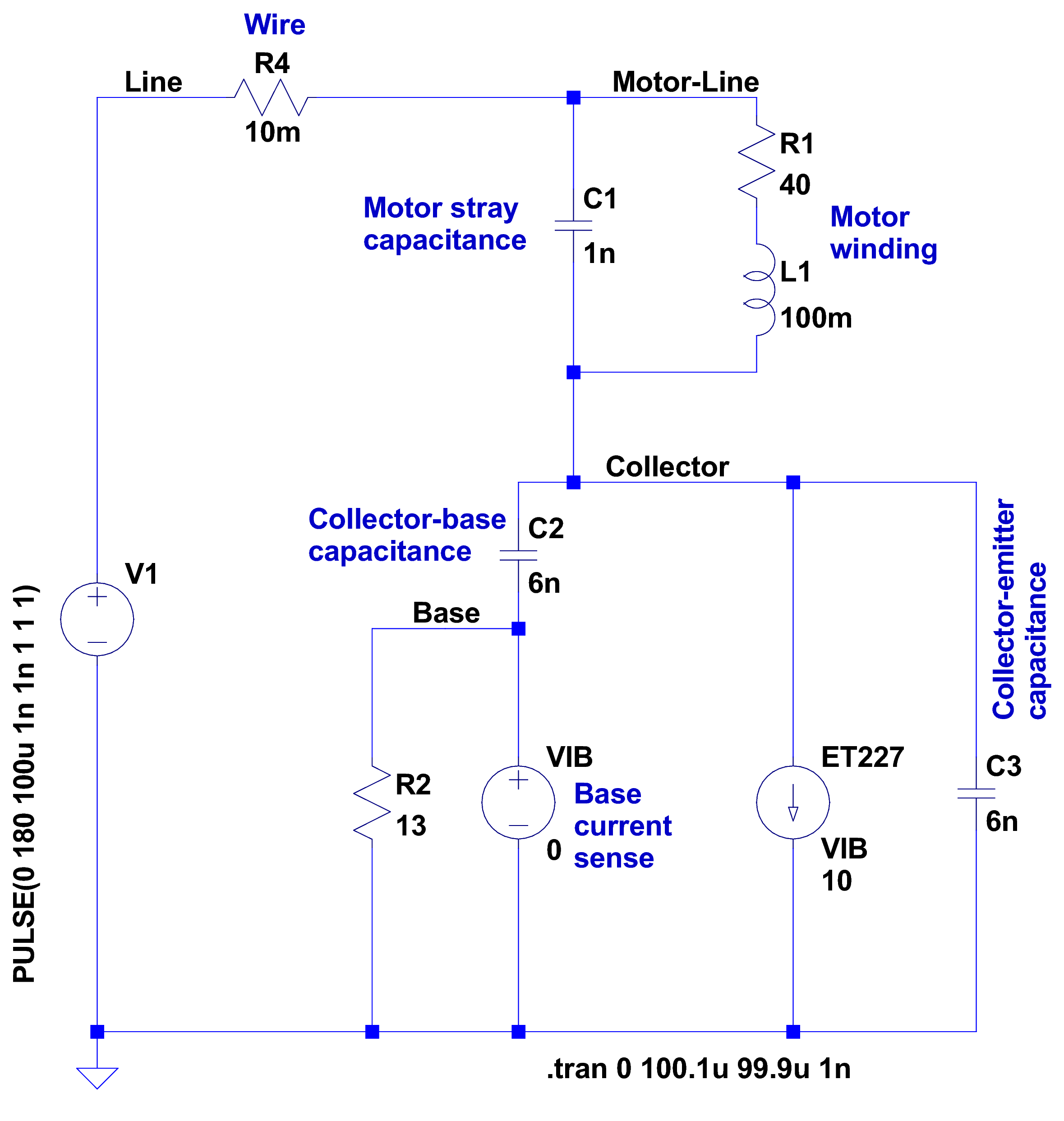
After having blown two ET227 transistors, I fiddled with some SPICE models to explore the ahem problem space. This seems to be the simplest model with all the relevant details:
Motor Transient – no NTC – schematic
A step change in the voltage source simulates the relay clicking closed with the AC line at a peak. R4 might resemble the total wiring resistance, but is more of a placeholder.
I measured 1 nF from each motor wire to the motor shell, so I assume a similar value from wire to wire across the winding. I can’t measure that, because, as far as my capacitance meters are concerned, the 40 Ω motor winding looks exactly like a resistor. R1 and L1 model the winding / commutator, but on the time scale we’re interested in, that branch remains an open circuit.
There’s no transistor model even faintly resembling a hulking ET227, so a current controlled current source must suffice. The 0 V VIB “source” in the base lead measures the base current for the CCCS labeled ET227, which applies a gain of 10 to that value and pulls that current from the collector node. R2 is the internal base-emitter resistor built into the ET227.
C2 is the 6 nF (!) collector-base capacitance I measured at zero DC bias on a good ET227. That’s much more than you’ll find on any normal transistor and I’m basically assuming it’s vaguely related to the Miller capacitance of small-signal fame. C3 is a similar collector-emitter capacitor; I can’t tell what’s going on under the hood without a whole lot of measurement equipment I don’t have.
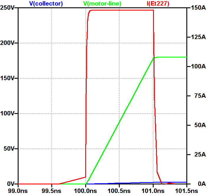
So, without further ado:
Simple Transient Model – current pulse
Whenever you see a simulation result like that, grab your hat in both hands and hunker down; the breeze from the handwaving will blow you right off your seat.
The key unknown: the rise time of the voltage step as the relay contacts snap closed. Old-school mercury-wetted relay contacts have rise times in the low tens of picoseconds. Figuring dry high-power contacts might be 100 times slower gives a 1 ns rise time that I can’t defend very strongly; it seems to be in the right ballpark. The green trace shows the input voltage ramping to 180 V in 1 ns, which is pretty much an irresistible force.
The motor shunt capacitance forms a voltage divider with the parallel base and collector capacitors, so the collector voltage shouldn’t exceed 180 * (1/(1+3)) = 45 V. In fact, the blue trace shows the collector voltage remains very low, on the order of 10 V, during the whole pulse.
The red trace shows the collector current hitting 150 A during the entire input ramp, which is exactly what you’d expect from the basic capacitor equation: I = C dv/dt. The current depends entirely on the absurdly fast 180 V / 1 ns rate: if the relay rise time is actually smaller, the current gets absurdly higher.
The ET227 datasheet remains mute on things like junction capacitance, damage done by nanosecond-scale high-current pulses, and the like.
Absolutely none of those numbers have even one significant figure of accuracy, but I think the overall conclusion that I’m blowing junctions based on transient startup currents through the collector holds water.
Adding four of those NTC power thermistors seems in order. This picture also shows the snubber hanging from the back of the ET227, but I eventually took that off because the simulations show it’s not doing anything useful and it does resonate with the 120 Hz halfwave supply:
HV Interface – snubber and thermistors
The thermistors get comfortably warm after a few minutes and settle out around 1 Ω apiece. Adding 4 Ω to the simulation reduces the current to 30 A during a 1 ns ramp, which number obviously depends on all the assumptions mentioned above.
I’ve been running it like that for a few hours of start-stop operation and the ET227 lives on, so maybe I can declare victory.
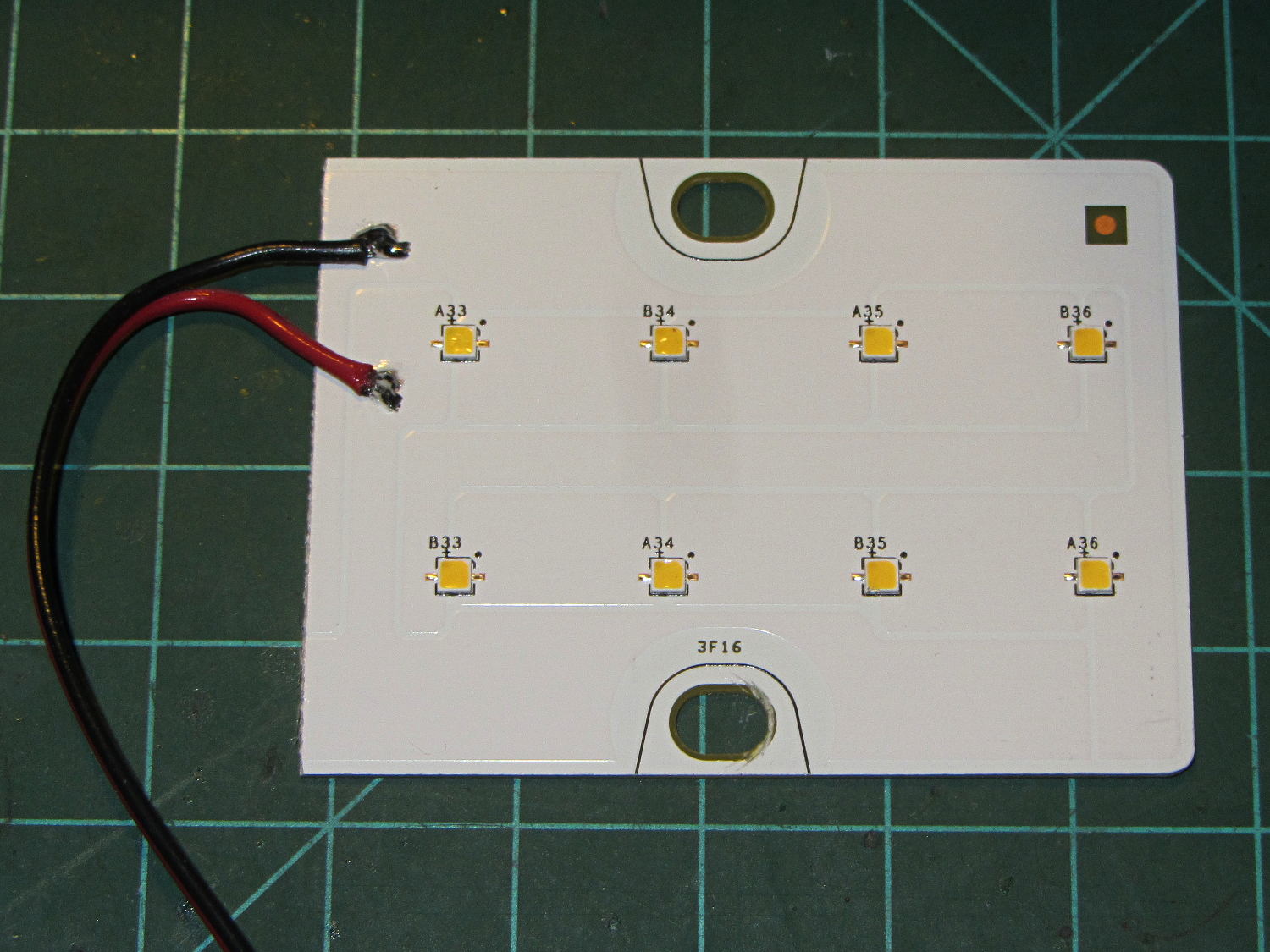
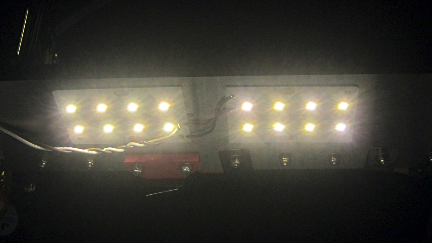
A surplus haul of 24 V / 150 mA white LED panels arrived:
LED Panel – 24 V 150 mA
I wired a pair to a 24 V wall wart and stuck them under the M2’s bridge supporting the X stage:
LED Panel – on M2 Gantry
I thought about epoxying them in place to get better heatsinking to the metal bridge. The ever-trustworthy description said the big copper baseplate meant the panels didn’t need any heatsinking, so I used tapeless sticky and will hope for the best. Should the sticky give out, then I’ll use epoxy.
They’re much better than the previous white LED strip, although it’s tough to tell in the pictures. The chain mail armor appears under the new lights; some older pictures will creep in from time to time.
We’ve been doing a lot of roasting and bought a not-dirt-cheap Taylor 1478 digital kitchen thermometer with a long probe wire to monitor the meat temperature. As soon as I unpacked it, I knew this would eventually happen:
Kitchen thermometer – nicked probe wire
The cable lasted just long enough to ensure the thermometer warranty expired; it’s a deliberate design flaw if I’ve ever seen one.
The thermistor inside the probe seems to be 100 kΩ at ordinary temperatures, although I’d be completely unsurprised to find that Taylor uses a slightly nonstandard resistance. Because nonstandard, of course.
Anyhow, replacement probes (*) are readily available from the usual Amazon suppliers, feature stainless steel braid sheathing and cost about as much as a whole new thermometer (albeit those still have cheap plastic insulation). With a replacement on order, I hauled the failed probe to the shop for an autopsy and possible resurrection…
Although I hoped that hammering out the crimp would release the thermistor, it was not to be. In retrospect, pulling on the probe wire probably killed it, but I didn’t know that at the time.
A spring intended to stabilize tubing while bending worked just fine to un-bend the probe:
Kitchen thermometer – unbending
But, alas, the thermistor still didn’t emerge from the more-or-less straightened probe.
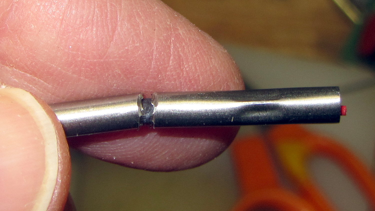
Some deft work with a Dremel cutoff wheel sliced enough off the stainless steel tube that I could splice the wires:
Kitchen thermometer – probe cutting
More cutoff wheel work smoothed the edges of that raw cut end, although the result wasn’t anything to show off.
The spliced and insulated probe definitely don’t win any awards, either:
Kitchen thermometer – probe rebuild
I doubt that the heatshrink tubing or silicone wrap underneath it would be suitable for roasts in the kitchen, but that’s moot: the probe remained intermittent.
If the new probe is also intermittent, then I’ll suspect the crappy 2.5 mm jack in the side of the thermometer…
(*) It’s not clear that a replacement probe for a 1470N thermometer will work with a 1478 thermometer. I’m gambling that Taylor wouldn’t be so stupidannoying deliberately obtuse as to use different probe thermistors, but that’s surely a bad bet. There’s no reason to believe Taylor actually makes any of this stuff, which means different models may come from entirely different designers / factories with entirely different supply chains.
It seems the batch of Energizer CR2032 lithium cells I bought a while ago reached the end of their shelf life:
Energizer CR2032 – short life
In point of fact, I replaced three CR2032 cells this month, all with anomalously short lives: one month counts as a complete failure. The Energizer date code YA isn’t helpful in determining when they were manufactured or what the shelf life might be.
Admittedly, I bought that batch in late 2009, so they might have used up most of their shelf life on somebody else’s shelf. There’s no way to know.
It’s not clear one can buy known-good cells from any supplier these days, as the counterfeiters evidently get genuine holograms from the same factory as the Brand Names.