With the Crash Test Dummy in place, Mary reports that the pedal required too much motion to reach the full speed position. The graph from the last time around shows the output as a function of pedal position:
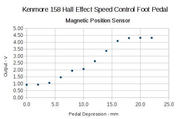
I’d done some fiddling around after recording that data, but it remained pretty close to the truth.
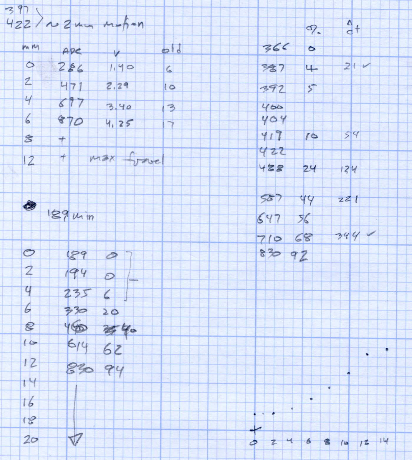
A new scale, not quite in the same spot as the previous one:
The two long lines mark the active region after I finished the mechanical tweaking described below; the pedal now produces nearly full output just beyond the 12 mm mark and has about that much overtravel. Measuring those values requires squeezing the pedal by hand, holding its position, and recording the ADC output dumped by the motor control program in the Arduino, a process that could be improved, but to not much benefit.
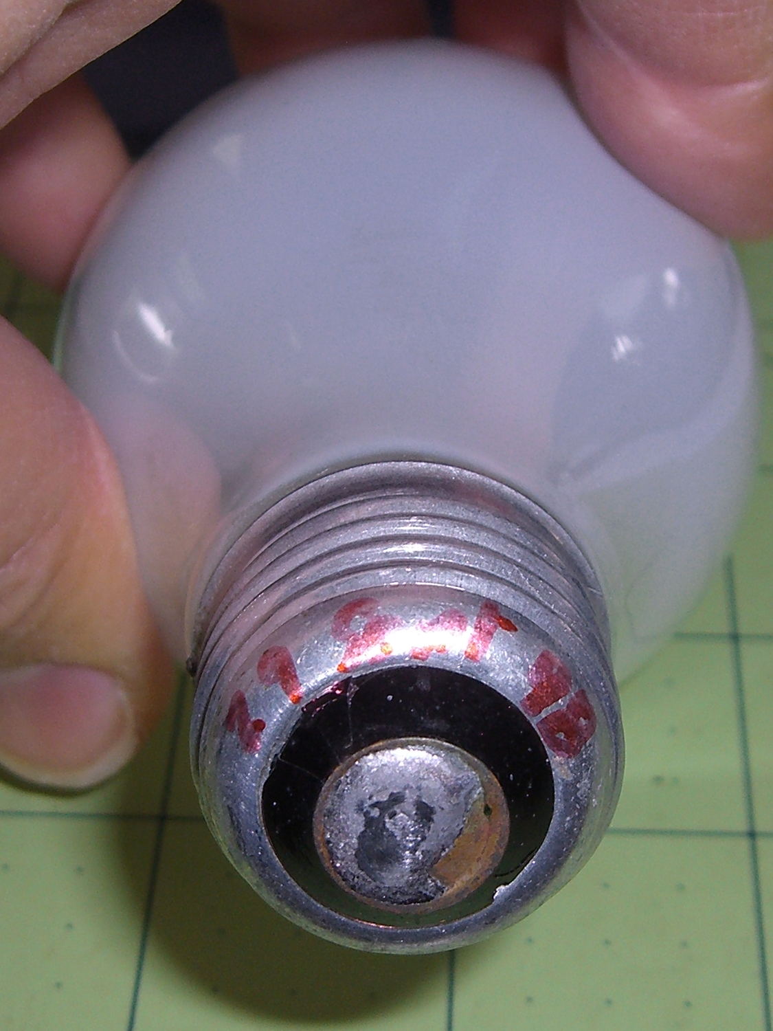
The original pedal writeup goes into the gory details, but the bottom line is that the mechanical motion producing that output range depends on the length of the rod from the actuator bar to the magnet.
The original version had a thin nut securing a screw inside the brass shaft to the actuator:

I later swapped the nut for three washers, after observing that the nut wasn’t actually necessary, but that produced too much dead travel at the beginning of motion.
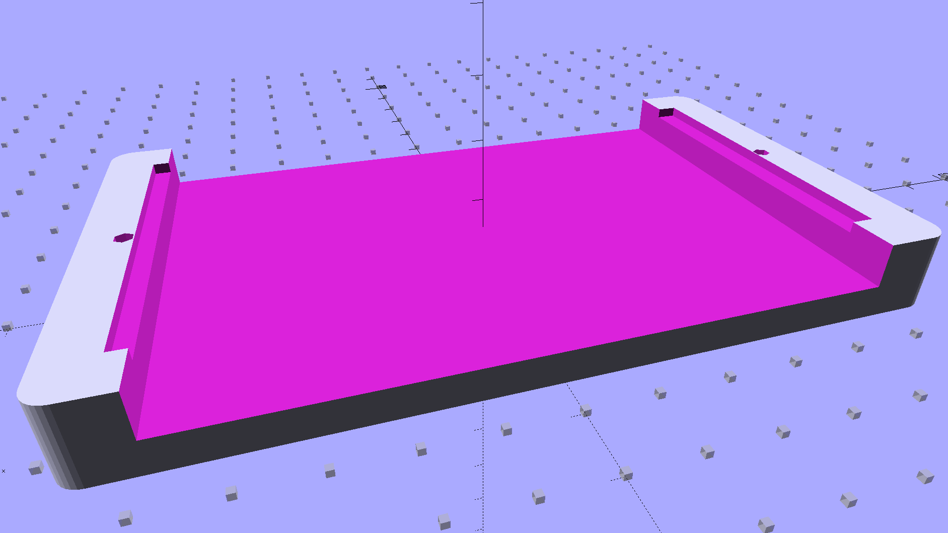
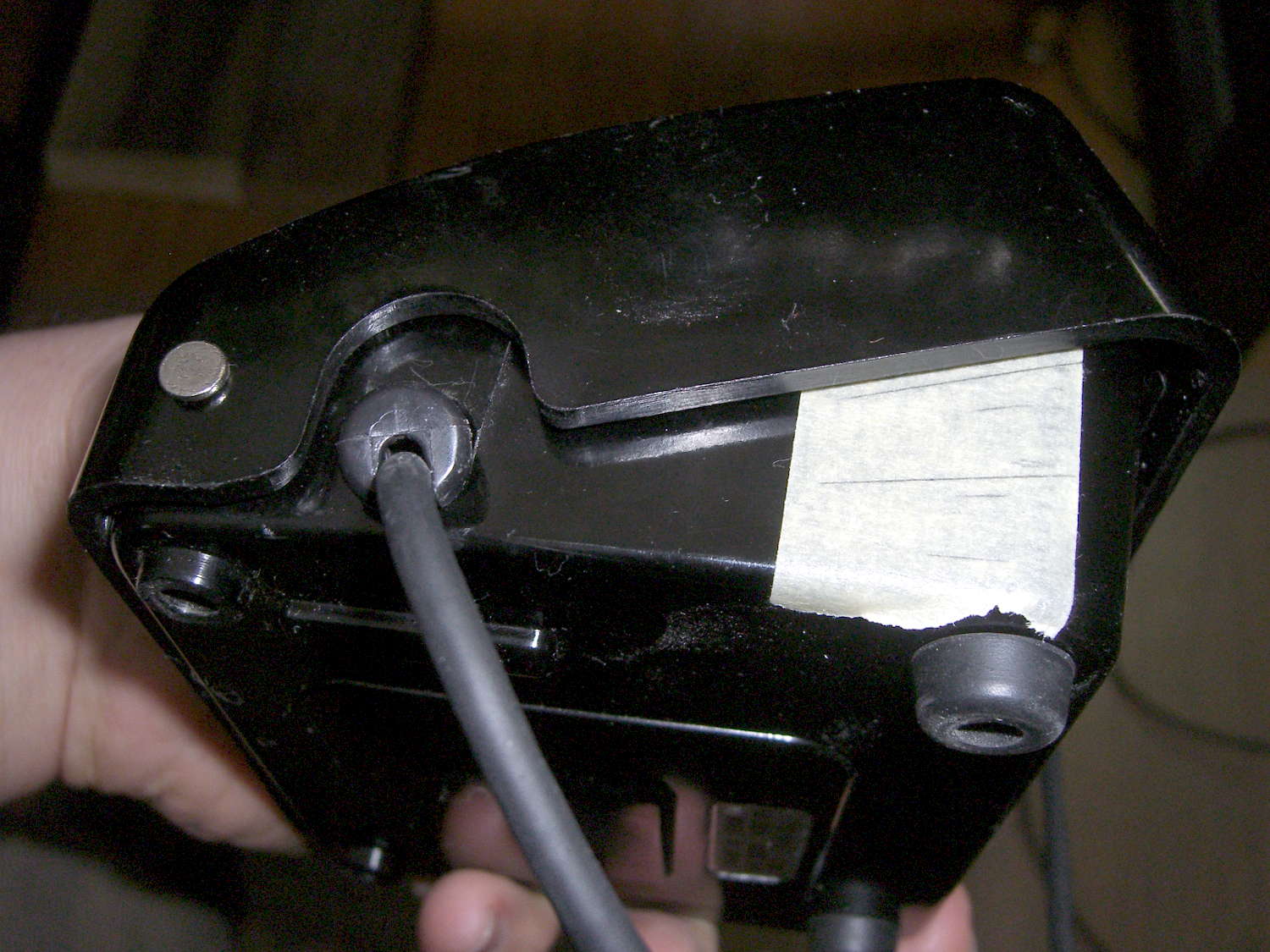
We discovered that the actuator bar could slip off the end of the ramp cast into the pedal cover, jamming the end of the ramp, making the case extremely difficult to disassemble, and causing heartache & confusion. Affixing a pair of rubber feet to the rear wall of the pedal case with tapeless sticky keeps the bar about half a millimeter further forward and eliminates that problem:
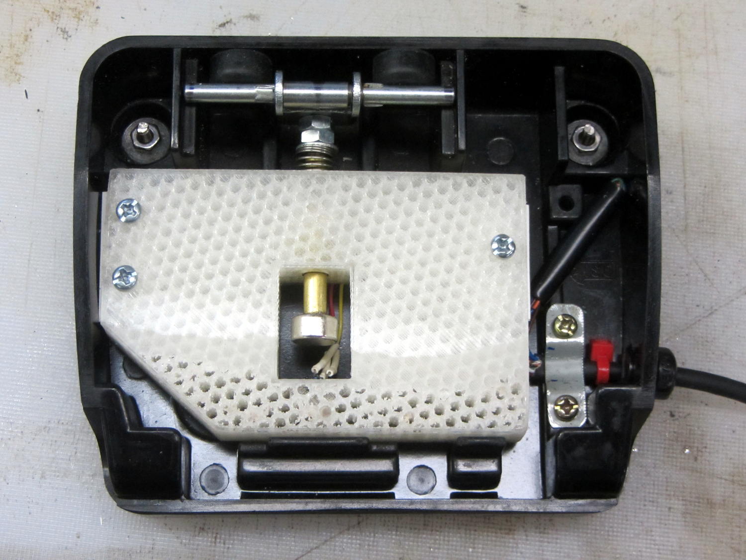
A second nut moved the brass rod forward, but that turned out to be a bit too much, so it now has a single, slightly thicker, nut. The 3D printed frame allows for far more travel in each direction than is strictly necessary, specifically to allow this fine tuning; it’s possible to make the rod’s resting position too close to the Hall effect sensor and have them collide at full travel, but I managed to avoid that.
It’s impossible to measure anything with the case disassembled: each change requires reassembling everything, measuring, and iterating.
After some of this & that, this graph shows the final output curve, with the Y axis in raw ADC counts at 100/div:
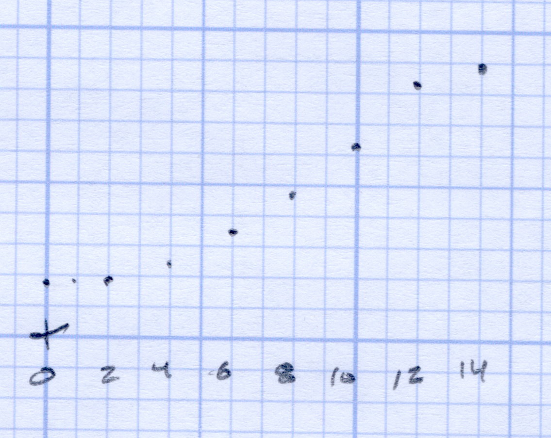
The first 3 mm doesn’t produce much change in the output, it smoothly changes to the more-or-less linear ramp up to 12 mm, then tapers off to full output beyond 14 mm. That’s pretty close to the original graph, with full throttle occurring a bit more than 2 mm earlier; the difference between the two scales may have some effect. In any event, Mary reports it feels much better.
Trust me: that matters.
The original data from the first and second mods, plus a teeny version of that graph: