Ed Nisley's Blog: Shop notes, electronics, firmware, machinery, 3D printing, laser cuttery, and curiosities. Contents: 100% human thinking, 0% AI slop.
Yeah, I’m sure that’s not what it means, but, still…
I don’t understand how the total cost of a nontrivial something shipped halfway around the planet can be less than the price I’d pay to return it. I’m certain it involves massive subsidies and mysterious cash flows that never break the surface of the eBay “Buy It Now!” pond.
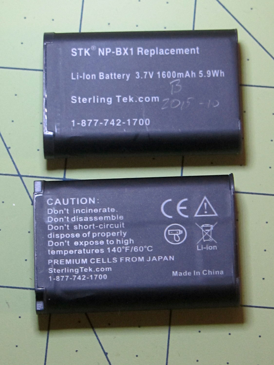
Because the first pair of Wasabi NP-BX1 batteries for the Sony HDR-AS30V camera faded to the point where they weren’t useful for a typical bike ride, I bought a pair of SterlingTEK (a.k.a. STK) NP-BX1 batteries that, like the Wasabi batteries, claimed to have a 1600 mA·h capacity. These are “second tier” batteries, not the cheap eBay crap I’ve already dismissed, and run a bit under $10 apiece.
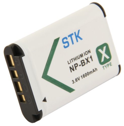
Here’s the picture from their product description:
SterlingTEK – STK NP-BX1 battery – as advertised
Here’s what arrived:
STK NP-BX1 batteries
Huh.
That’s a red flag, right there. It’s remarkably tempting to ship a good product for a while, then swap in much cheaper junk that can ride on the good reviews. Not saying that’s what happened, but it’s a possibility.
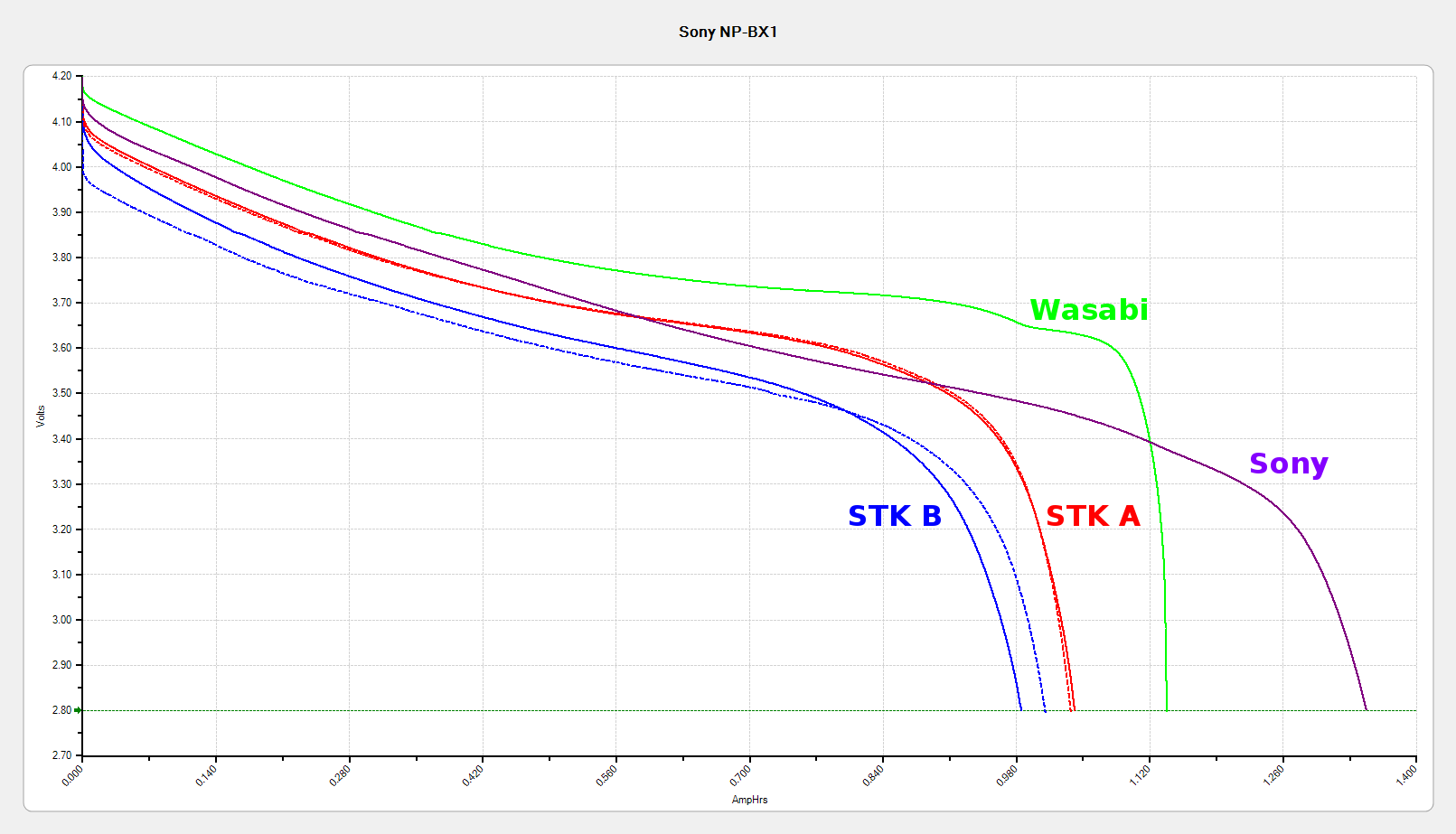
Here’s how they performed:
Sony NP-BX1 – Sony Wasabi STK – as received
The red and blue curves show that the STK batteries produced less than 1000 mA·h in their first two charges, with the blue battery (I labeled it B) showing considerable variation that suggests it’ll suffer early failure. The green curve shows one of those Wasabi batteries and the purple curve is the OEM Sony battery, both in as-received condition.
SterlingTEK will send two more batteries, in the belief that I received two sub-standard samples. We shall see…
All the tests are at 500 mA, approximately half the camera’s load. Oddly, the numeric values along the mA·h axis work out pretty close to the actual runtime in hours:
Sony – 1:30
Wasabi D – 1:15
Wasabi B – 0:40
Given that a typical bike ride takes an hour, the two year old Wasabi B battery’s 40 minute runtime isn’t useful. The Wasabi D battery is a bit over a year old and looks very much like the B battery did last year.
The Wasabi batteries march through the camera and charger in order, so each one gets used about once a week. The Sony battery gets used once every half-dozen complete cycles, just so I have a standard “good” battery.
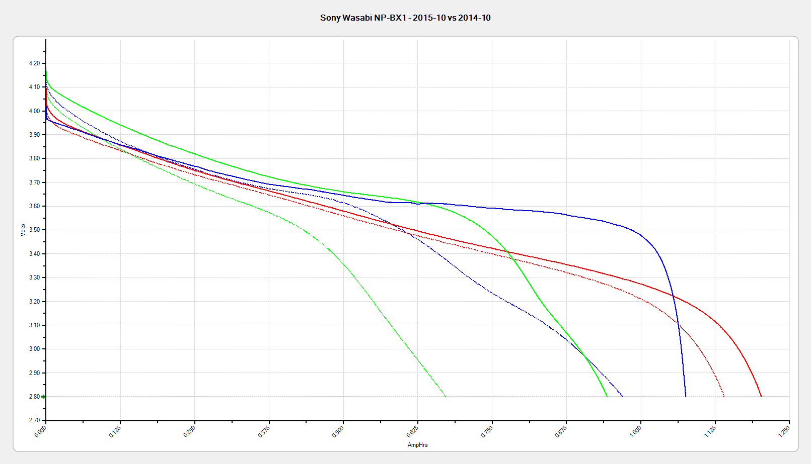
The Sony and Wasabi B cells over the course of two years:
Sony NP-BX1 – OEM Wasabi – 2015-10 2014-10 2014-01
Much to my surprise, the Wasabi batteries started out slightly better than the Sony OEM battery, at least as measured by the available voltage and energy. The camera runs from an internal switching power supply, so the area under the curve (basically equal to energy in W·h) above the cutoff voltage is all that matters.
In round numbers, I can expect 100 cycles out of each battery before the run time drops below the ride time; at $10/battery, that’s a dime a ride. Any claims that the batteries can be recharged “1000 times!” may be true, but they’ll have a useless fraction of their original capacity by then.
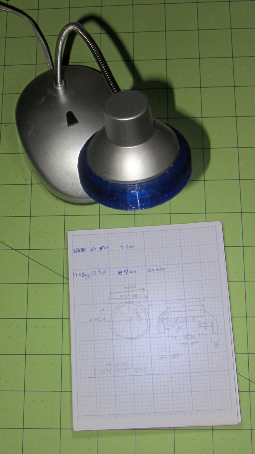
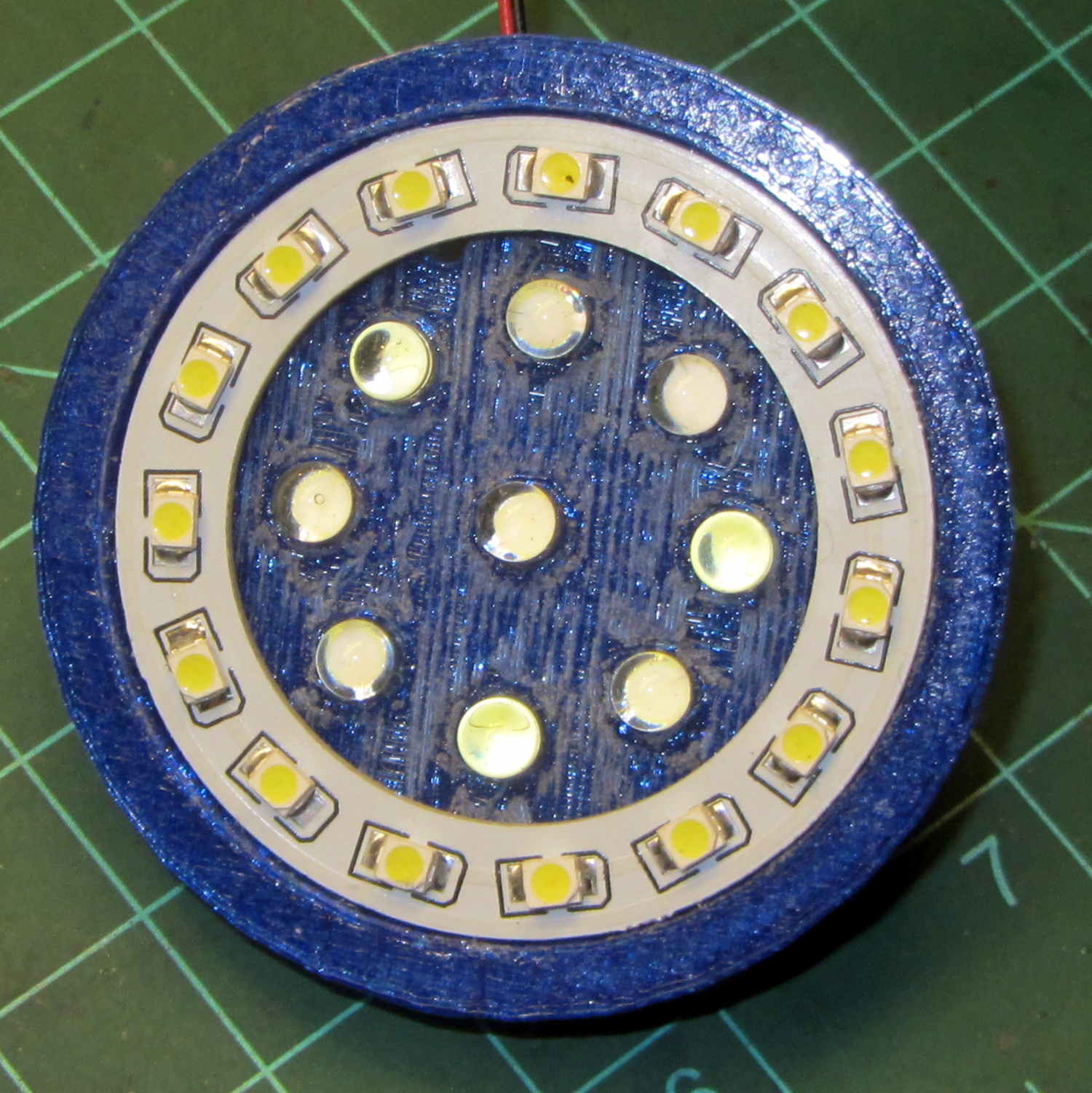
A defunct desk lamp emerged from the clutter and cried out for bright, new LEDs. This adapter puts a small LED ring and nine white LEDs on the original lamp head:
Ring Light Mount – in operation
Peering into the business end, before mounting it on the lamp, shows some abrasive adjustment on the inside layer:
Ring Light Mount – LEDs installed
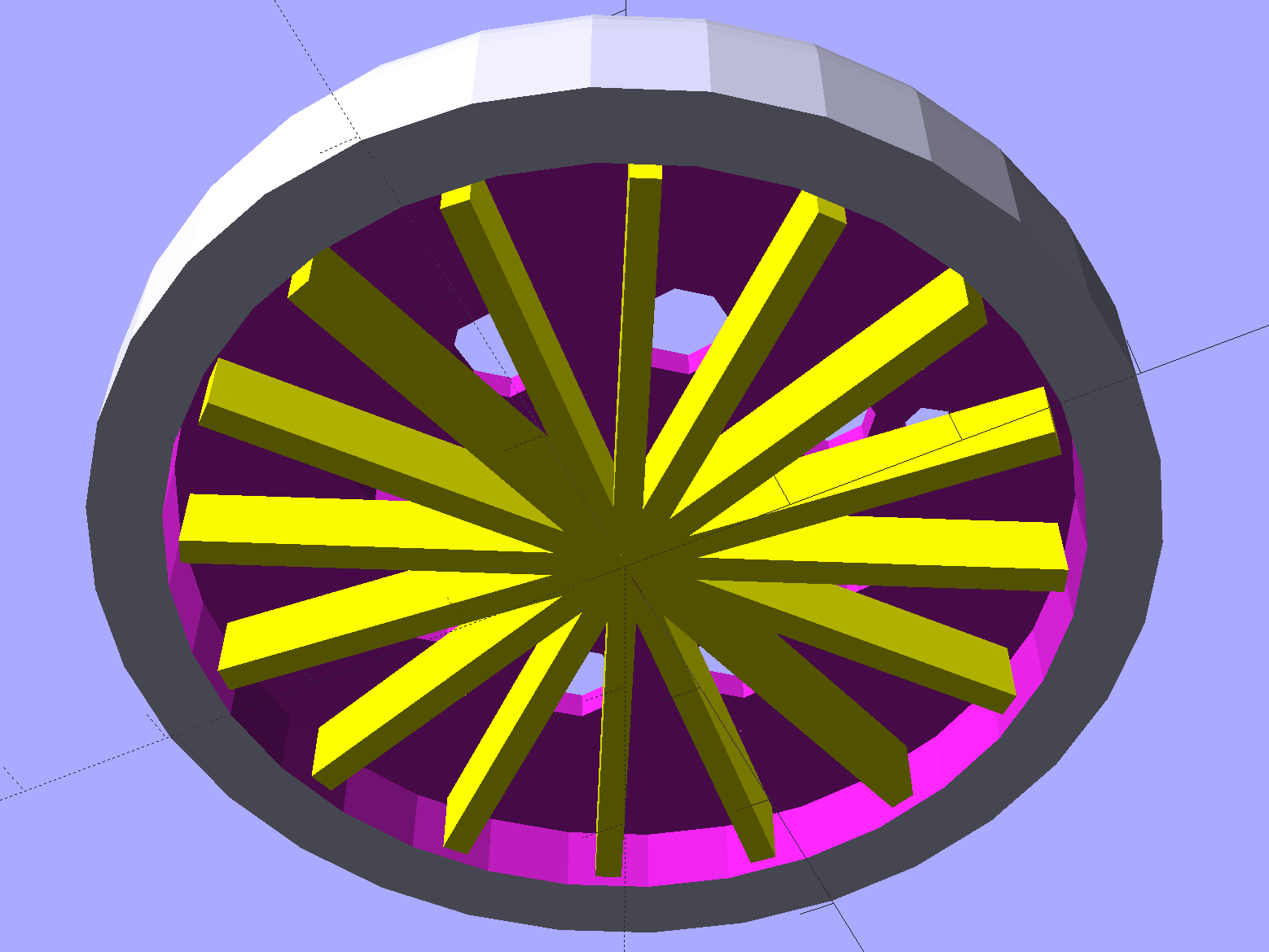
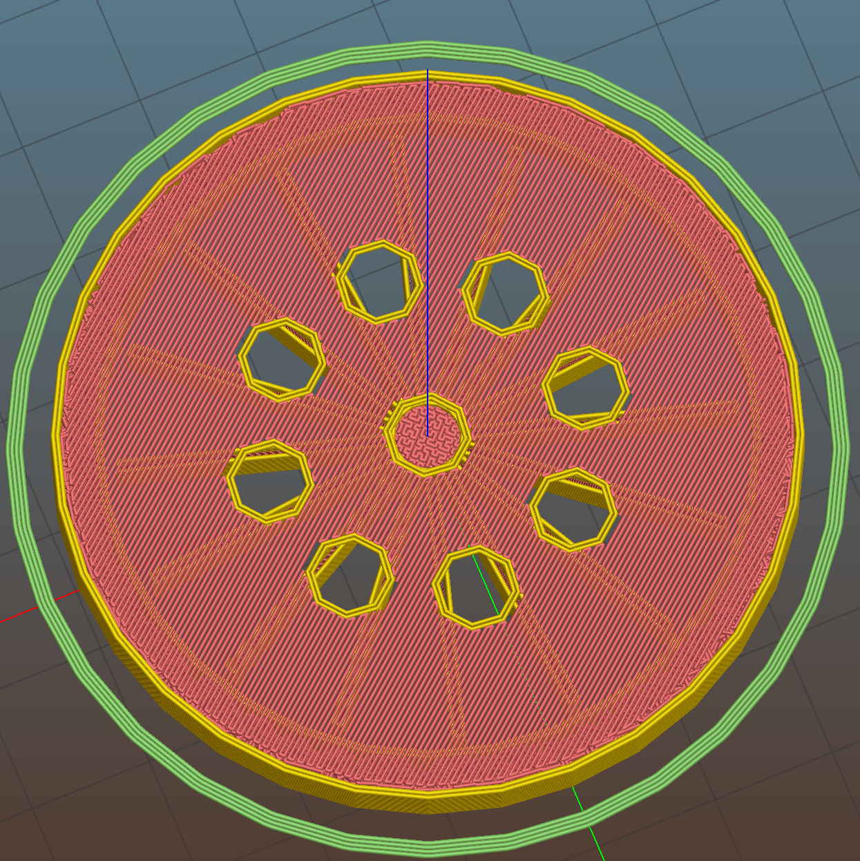
That layer printed over a quick-and-easy support spider:
Ring Light Mount – solid model – bottom
The Slic3r preview looking down through the layer just over the support shows that the perimeter of those LED holes doesn’t have much support:
Ring Light Mount – Slic3r preview – bridge layer
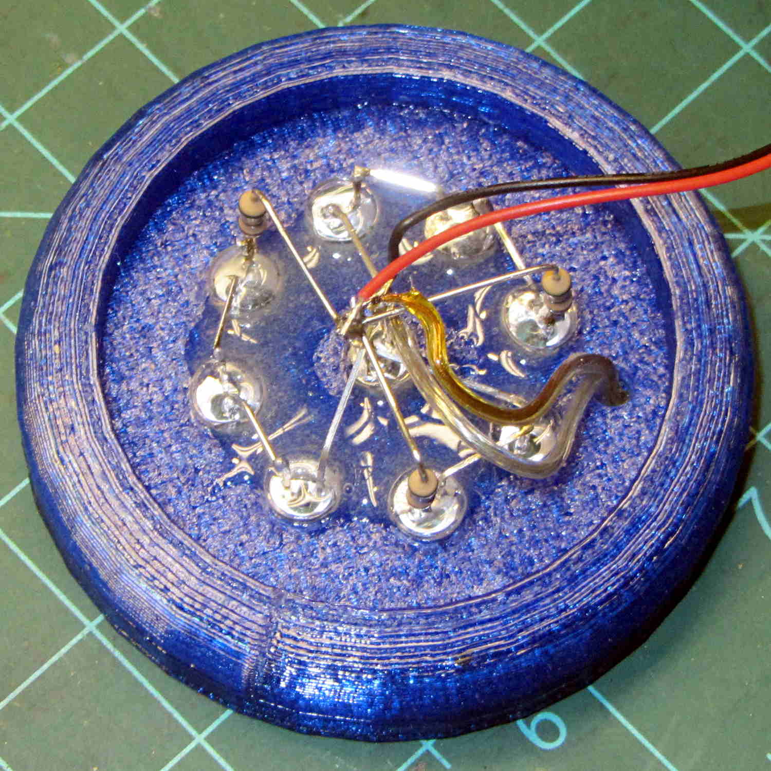
The obvious threads drooped in the predictable way, so I just clipped them off, sanded the high spots into submission, and epoxied everything in place:
Ring Light Mount – LED wiring
That nice Hilbert Curve infill is completely wasted inside the OEM shade, but the smooth curve around the rim had to be on the top surface.
Rather than beefing up the support, you should print the bottom ring (or the top rim) separately, then glue it back on, but I wanted to see how well simple support worked with PETG.
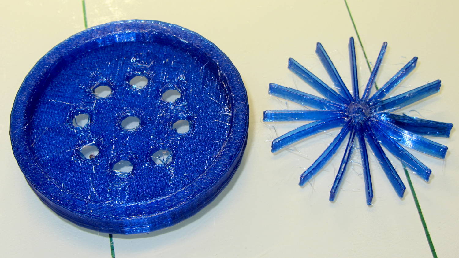
It came out reasonably well:
Ring Light Mount – support spider
That’s far more hair than usual, even for PETG, because I made the spider’s legs exactly three thread widths wide. Slic3r reduced the single infill thread to, literally, a hair that didn’t stick to the platform; the model now has four-thread-wide legs.
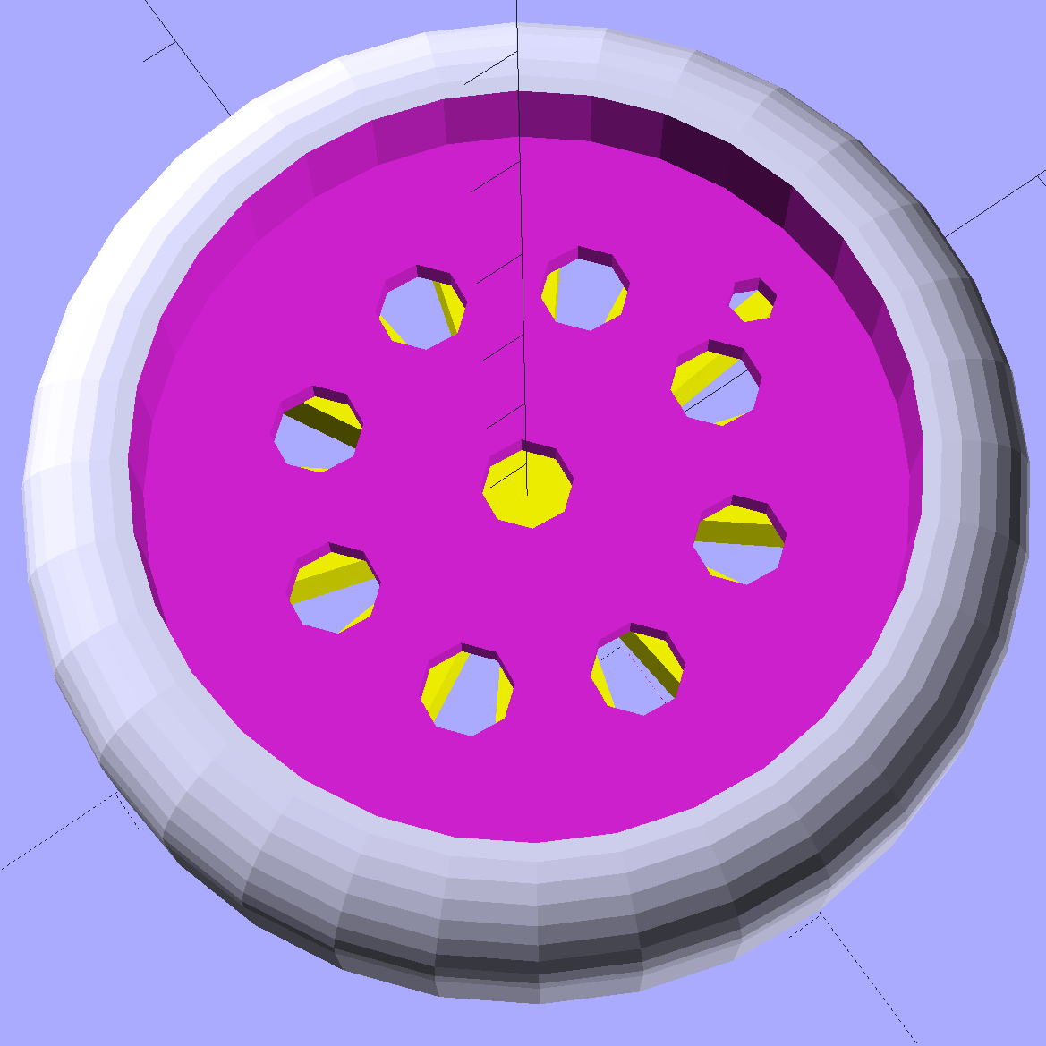
Slic3r’s automatic support would do a better job of holding up the underside, albeit with more plastic and printing time:
Ring Light Mount – Slic3r preview – auto support
The top view looks about like you’d expect:
Ring Light Mount – solid model – top
Those two solid models show the small hole for the LED ring wiring, which I drilled into the as-printed plastic. The original layout included just the LED ring, with the wire through a big central hole, but then I realized the wall wart had enough moxie for a few more LEDs. So it goes.
Anyhow, the lamp provides just enough illumination below my big monitors to suffice. The gooseneck might not be quite long enough, but that’ll be another project…
The OpenSCAD source code:
// LED Ring Light Mount
// Ed Nisley KE4ZNU October 2015

DoSupport = true;

//- Extrusion parameters must match reality!

ThreadThick = 0.25;
ThreadWidth = 0.40;

HoleWindage = 0.2;

Protrusion = 0.1;			// make holes end cleanly

inch = 25.4;

function IntegerMultiple(Size,Unit) = Unit * ceil(Size / Unit);

//----------------------
// Dimensions

NumSides = 8*4;						// number of sides on each "cylinder"

LENGTH = 0;
ID = 1;
OD = 2;

Shade = [6.0,45.2,47.5];			// threaded end of OEM lamp shade
RingLED = [4.5,36.0,51.0];

SpotLED = [2.0,0,5.0];				// discrete LEDs in center
NumSpots = 8;						// discrete LEDs around the one in the middle

Support = [(RingLED[LENGTH] - 1*ThreadThick),0,(RingLED[OD] - 4*ThreadWidth)];
NumSupports = NumSides/2;

ThreadBase = RingLED[LENGTH] + SpotLED[LENGTH];
OAHeight = ThreadBase + Shade[LENGTH];

//----------------------
// Useful routines

module PolyCyl(Dia,Height,ForceSides=0) {			// based on nophead's polyholes

  Sides = (ForceSides != 0) ? ForceSides : (ceil(Dia) + 2);

  FixDia = Dia / cos(180/Sides);

  cylinder(r=(FixDia + HoleWindage)/2,
           h=Height,
	   $fn=Sides);
}

//----------------------
// Build it

	difference() {
		union() {																				// overall shape
			translate([0,0,ThreadBase])
				rotate_extrude(convexity = 2, $fn=NumSides)
					translate([Shade[OD]/2,0])
						circle(r=Shade[LENGTH],$fn=NumSides);
			cylinder(d=(Shade[OD] + 2*Shade[LENGTH]),h=ThreadBase,$fn=NumSides);
			translate([0,0,ThreadBase])
				cylinder(d=Shade[OD],h=Shade[LENGTH],$fn=NumSides);
		}

		translate([0,0,ThreadBase - Protrusion])
			cylinder(d=(Shade[ID] + HoleWindage),h=(Shade[LENGTH] + 2*Protrusion),$fn=NumSides);	// opening for shade thread

		translate([0,0,-Protrusion])
			cylinder(d=(RingLED[OD] + HoleWindage),h=(RingLED[LENGTH] + Protrusion),$fn=NumSides);	// opening for LED ring

		rotate(180/NumSides)																		// LED ring power wire
			translate([RingLED[ID]/2,0,0])
				rotate(180/6)
					PolyCyl(2.5,OAHeight,6);

		rotate(180/8  - 180/NumSides)
			PolyCyl(SpotLED[OD],OAHeight,8);														// central LED SpotLED

		for (i=[0:NumSpots-1])																		// surrounding spots
			rotate(i*360/NumSpots - 180/NumSides)
				translate([(RingLED[ID] - 2*SpotLED[OD])/2,0,0])
						rotate(180/8)
							PolyCyl(SpotLED[OD],OAHeight,8);
	}

//-- Support structure

	if (DoSupport)
		color("Yellow")
		rotate(180/NumSides)													// align bars to flat internal faces
			for (i=[0:NumSupports/2 - 1]) {
				rotate(i * 360 / NumSupports)
					translate([0,0,Support[LENGTH]/2])
						cube([Support[OD],4*ThreadWidth,Support[LENGTH]],center=true);
			}
Restocking the AA and AAA alkaline cell supply delivered this example of underprotection from Amazon:
Amazon Packaging – alkaline batteries
I think that scrap of plastic was once an air pillow, but it sure didn’t last long and definitely didn’t fill the entire space around the boxes.
Allowing that much mass to thrash around inside the box can’t possibly be a Good Thing, even if the cells weren’t damaged. One would hope they’d do a better job with lithium cells.
The shelf that collects old hard drives filled up, so I’ve been wiping the data before recycling them. This takes a while, but we know what happens when your hardware falls into unexpected hands. The routine goes a little something like this…
Set the drive’s jumper to Master, plug the drive into the USB adapter, plug the adapter directly into a USB port on the PC (because outboard hubs tend to be flaky), make sure there’s no valuable data, unmount.
time sudo dd if=/dev/urandom of=/dev/sdc bs=4096
[sudo] password for ed:
dd: error writing ‘/dev/sdc’: No space left on device
73259047+0 records in
73259046+0 records out
300069052416 bytes (300 GB) copied, 22276.7 s, 13.5 MB/s

real	371m19.003s
user	0m22.884s
sys		370m34.906s
Good old dd works for me; the only trick is not obliterating the system’s main hard drive with a simple finger fumble. Numbers from /dev/urandom suffice for this purpose; that’s where most of the packaged programs get their data, too. I do hardcore style, just because.
Ordinary desktop drives, at least those from long ago, can write at a bit over 12 MB/s → 40 GB/h on the average, with the higher peak rates that generally appear in the drive descriptions remaining an occasional sight. They won’t go much faster, even when plugged directly into the system board, but it’s not as if I sit there waiting until it’s done. USB 2.0 “high speed” transfers can hit 60 MB/s, including all the overhead, so that’s not the limiting factor; I’d expect the adapter’s firmware to throttle the data long before the bus strangles.
Use gparted to write a fresh partition table with a single NTFS (because the next user will probably run Windows) partition labeled Scrubbed spanning the entire drive.
Then stack the drive neatly on the outbound heap:
Scrubbed hard drives
That cardboard box isn’t quite as full of unscrubbed drives as it was a few weeks ago.
The stack in the back contains all those worthless 30 to 80 GB 5400 RPM drives from old Dells, plus a few 1.5 and 2.0 (!) GB drives from who knows where. I have a plan for those platters…
If the 1-48 on the side of the tube base (facing away in the picture) means anything, then General Electric built it in January 1948.
The pinout view in the datasheet assumes you’re looking at the bottom of the socket, which makes perfect sense given the hand-wired chassis construction techniques of the day:
0D3 Voltage Regulator Tube – pinout
So the view is backwards when seen from the top, not that you’d ever need it:
Ceramic octal tube socket – 0D3 pinout
The internal jumper across pins 3-7 allows you to disconnect the downstream circuit when the regulator isn’t in the socket, which is a Very Good Idea with a shunt regulator.
Not having a 200 V power supply ready to hand, but having recently restocked the 9 V alkaline battery box, this actually worked:
0D3 voltage regulator test setup
That’s 16 x 9-ish V = 150 V across the battery terminals, plus a 50 V adjustable bench power supply coming in on clip leads from the upper right, with current shown on a digital panel meter across a 1 Ω sense resistor. The classic 1.5 kΩ carbon resistor emerged from from a coffee can of parts that Came With The House™ and seemed appropriate for the occasion.
The tube conducts a few milliamps through a small plasma filament discharge at 150 V. The current ramps up to about 10 mA as the supply voltage increases to 180 V, whereupon the tube fires and the current jumps to 30 mA (which is less than the spec, but I ran the power supply in constant-current mode to avoid whoopsies).
Reducing the current to 10 mA slightly reduces the area involved in the plasma discharge, but the tube still produces a nice display through the mica spacer / insulator atop the plate:
0D3 voltage regulator – 10 mA current
That isn’t quite in focus, but should give you the general idea.
I didn’t measure the operating voltages across the tube, mostly because I didn’t want more cheap clip leads cluttering the bench.
It’d make a very low intensity nightlight that dissipates a watt or two. Boosting the current to the absolute maximum 40 mA would brighten it up a bit, but dissipating 6 W in the tube probably won’t do it any good.
This obviously calls for an Arduino monitoring the tube current with a Hall-effect sensor and regulating it with a hulking MOSFET…