Ed Nisley's Blog: Shop notes, electronics, firmware, machinery, 3D printing, laser cuttery, and curiosities. Contents: 100% human thinking, 0% AI slop.
The dual switch controlling the bathroom lights began requiring some fiddling, which was not to be tolerated. After replacing the switch, I cracked the old one open to see what’s inside…
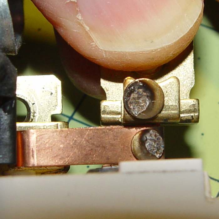
The failed side of the switch controlled the lights over the sink:
Light switch contacts – lights
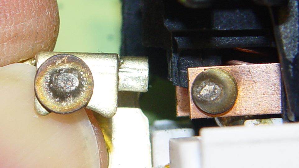
The side for the ceiling vent fan + light got much less use, still worked, and look a bit less blasted.
Light switch contacts – ceiling fan
Not much to choose between the two. It’s been running for nigh onto two decades, so …
An RTL-SDR receiver & Ham It Up RF upconverter arrived, with the intent of poking at LF signals. The upconverter circuit board also contains a mostly populated RF noise source:
Ham-It-Up v1.3 noise source – schematic
Being a sucker for noisesources, I spent some time pondering the circuitry.
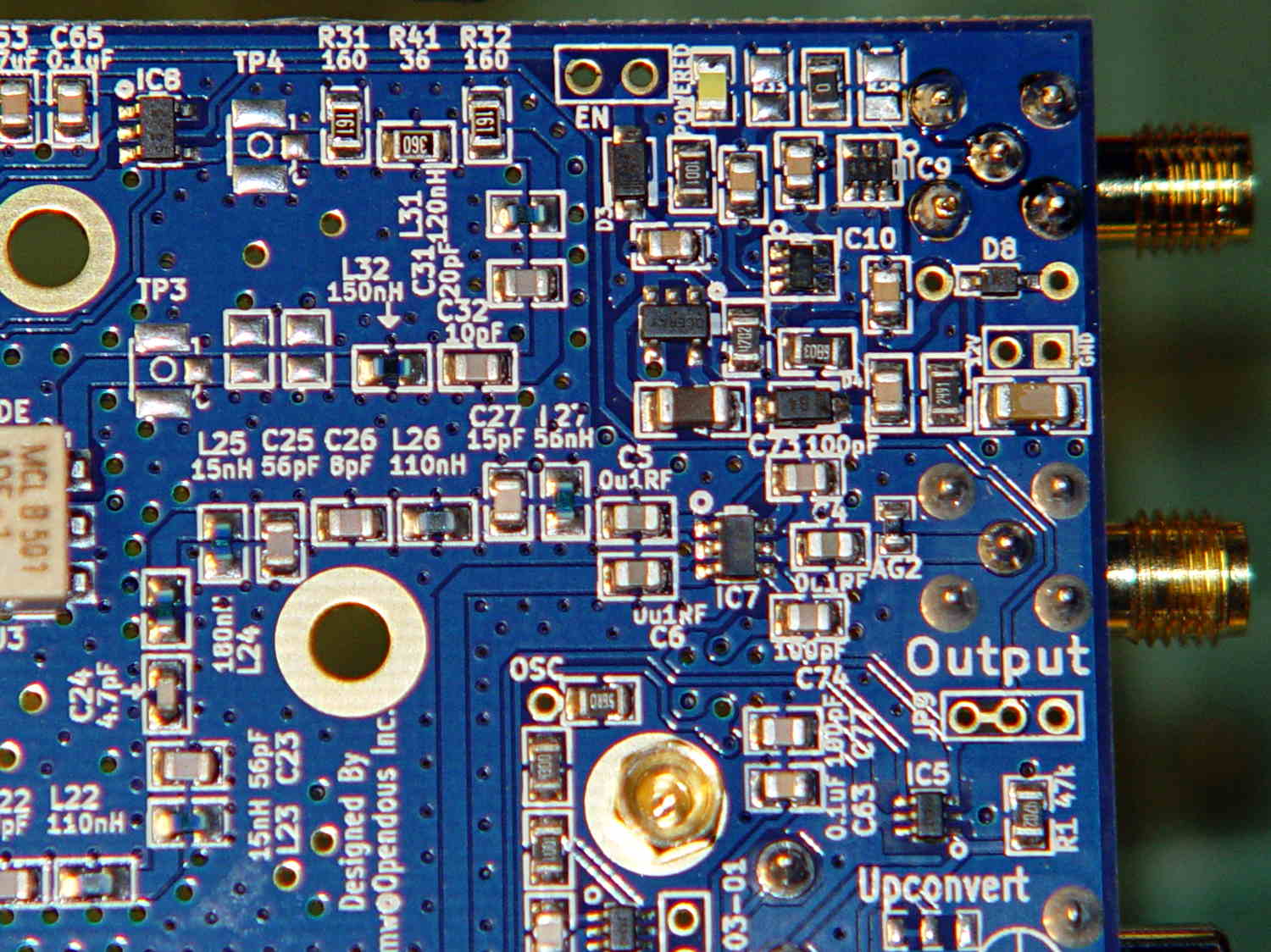
The as-built board has a 0 Ω jumper instead of the 6 dB pad along the upper right edge:
Ham-It-Up v1.3 – noise components
The previous version had a pi bandpass filter in place of the pad and you could certainly repopulate it with two caps and a teeny inductor if you so desired.
I added the SMA connector, which isn’t quite identical to the IF output connector above it:
Ham-It-Up v1.3 – noise SMA
That will require a new hole in the end plate that I’ll get around to shortly. It also needs an external switch connected to the Enable jumper, but that’s in the nature of fine tuning.
I’m awaiting a handful of adapters & cables from halfway around the planet…
The LED’s aluminum baseplate (perhaps there’s an actual “board” inside the yellow silicone fill) is firmly epoxied to a small heatsink from the Big Box o’ Heatsinks, chosen on the basis of being the right size and not being too battered.
The rather limited specs say the LED supply voltage can range from 9 to 12 V, suggesting a bit of slack, with a maximum dissipation of 3 W, which definitely requires a heatsink.
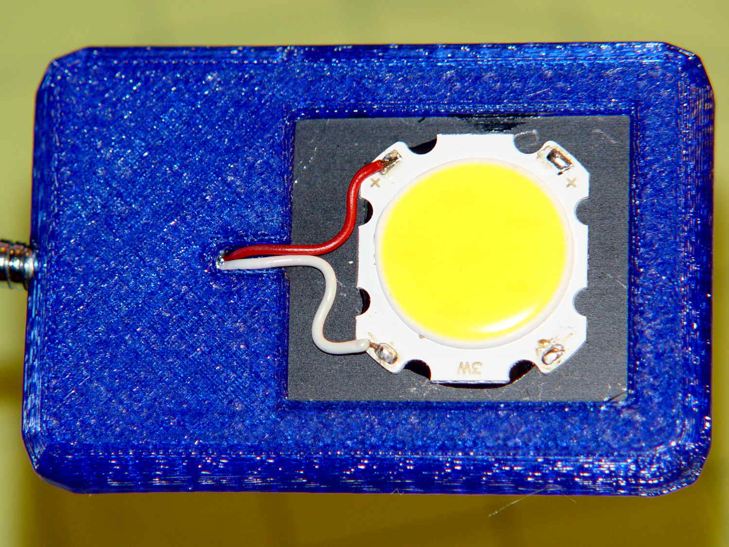
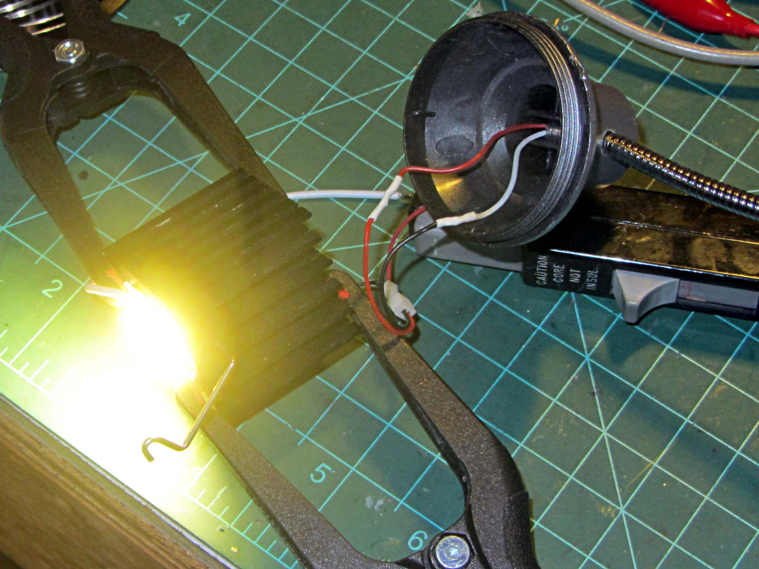
The First Light test looked promising:
COB LED Desk Lamp – first light
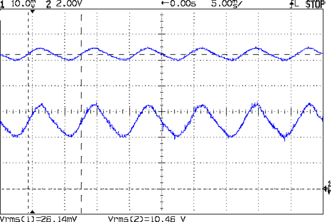
That’s driven from the same 12 VDC 200 mA wall wart that I used for the failed ring light version. Measuring the results shows that the supply now runs at the ragged edge of its current rating, with the output voltage around 10.5 V with plenty of ripple:
COB LED V I 100ma div
The 260 mA current (bottom, trace 1 at 100 mA/div) varies from 200 to 300 mA as the voltage (top, trace 2 at 2 V/div) varies between 10 V and a bit under 11 V. If you believe the RMS values, it’s dissipating 2.7 W and the heatsink runs at a pleasant 105 °F in an ordinary room. The wall wart gets about as warm as you’d expect; it contains an old heavy-iron transformer and rectifier, not a trendy switcher.
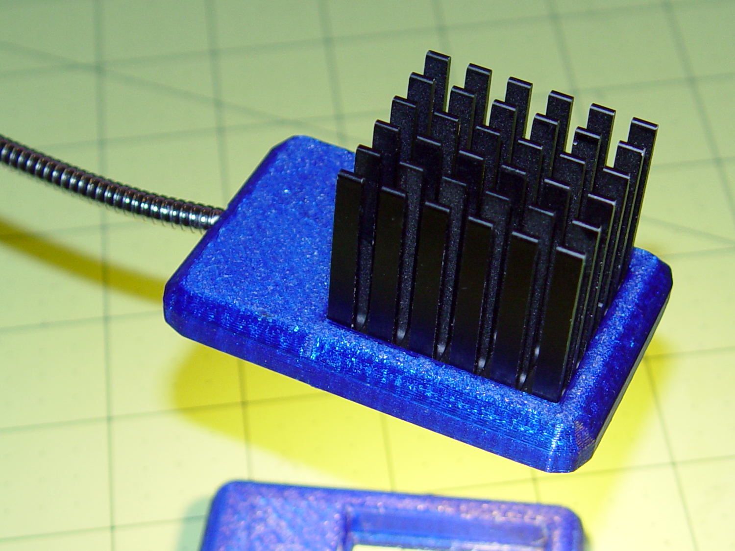
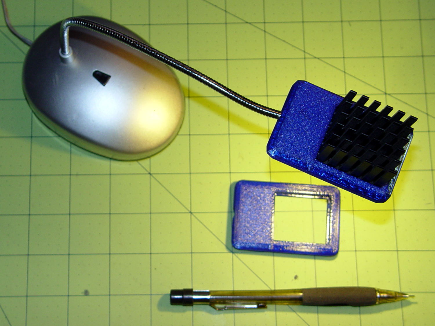
The heatsink mount looks nice, in a geeky way:
COB LED Desk Lamp – side detail
The left side must be that long to anchor the gooseneck; I thought about tapering the slab a bit, but, really, it’s OK the way it is. Dabs of epoxy hold the gooseneck and heatsink in place.
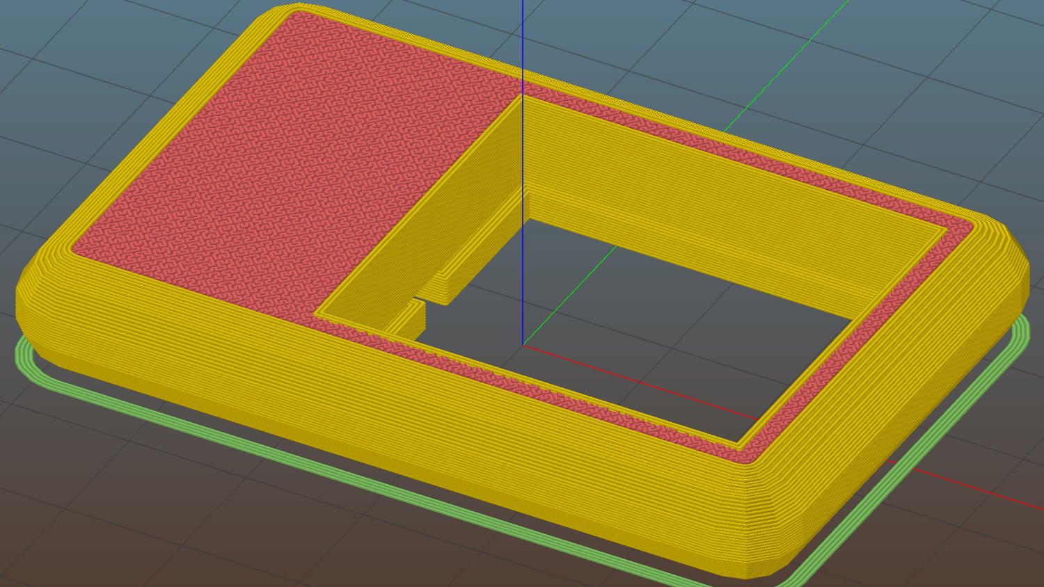
The heatsink rests on a small ledge at the bottom of the slab that’s as tall as the COB LED is thick, with a wire channel from the gooseneck socket:
COB LED Heatsink mount – Slic3r
The Hilbert Curve infill on the top produces a textured finish; I’m a sucker for that pattern.
The old lamp base isn’t particularly stylin’, but the new head lights up my desk below the big monitors without any glare:
This file contains hidden or bidirectional Unicode text that may be interpreted or compiled differently than what appears below. To review, open the file in an editor that reveals hidden Unicode characters.
Learn more about bidirectional Unicode characters
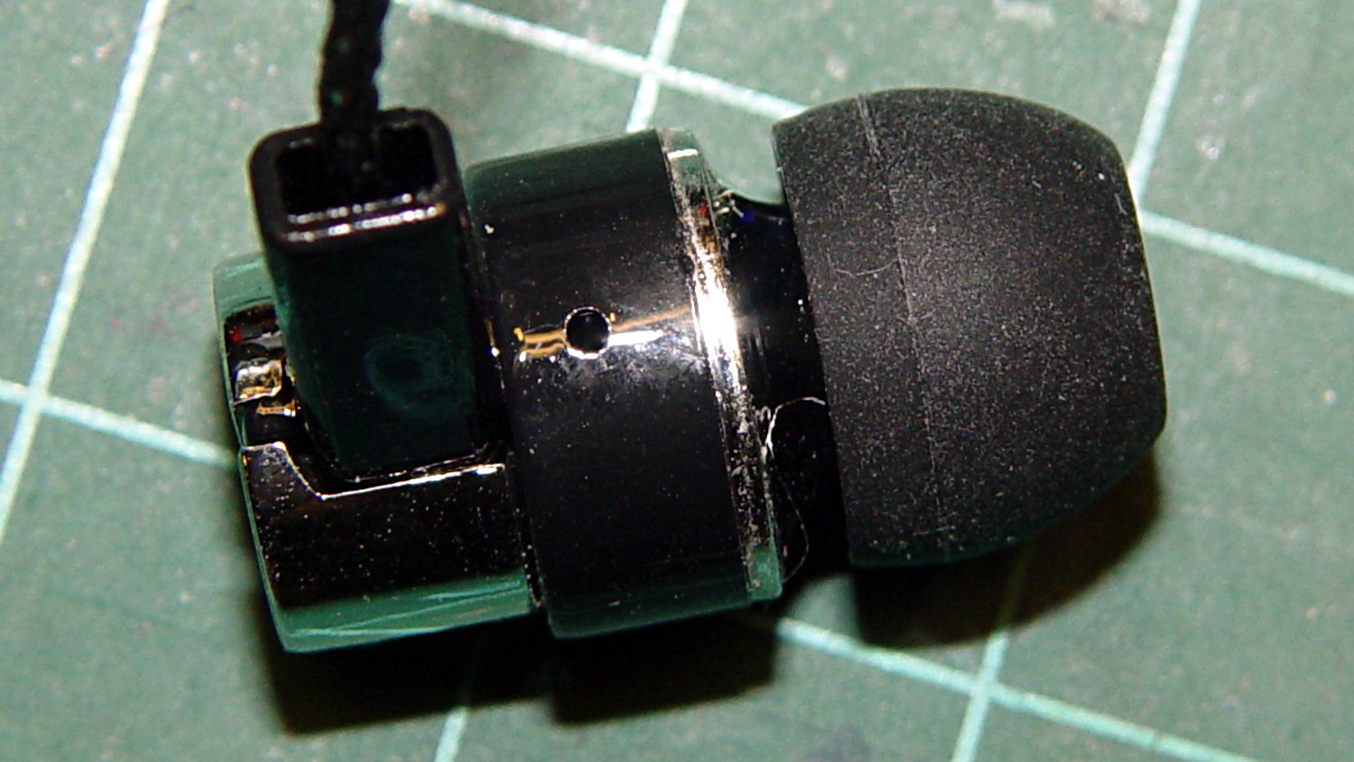
A bag arrived from halfway around the planet, bearing five sets of cheap earbuds. There was no way to tell from the eBay description, but they’re vented on the side:
Cheap earbud – side vent detail
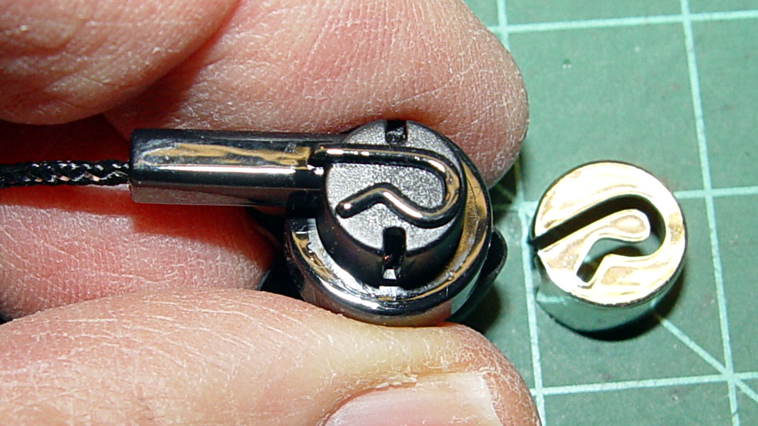
And also to the rear, down inside those deep slots below the chromed plastic cover:
Cheap earbud – back openings
The raised lettering is a nice touch; the other earbud has a script L.
The PET braid over the fragile wire should withstand a bit more abuse than usual. The strain relief isn’t anything to cheer, though, consisting of that rectangular channel with the wire loose inside. I figured I’d start minimal and fix whatever crops up; I have nine more earbuds to go.
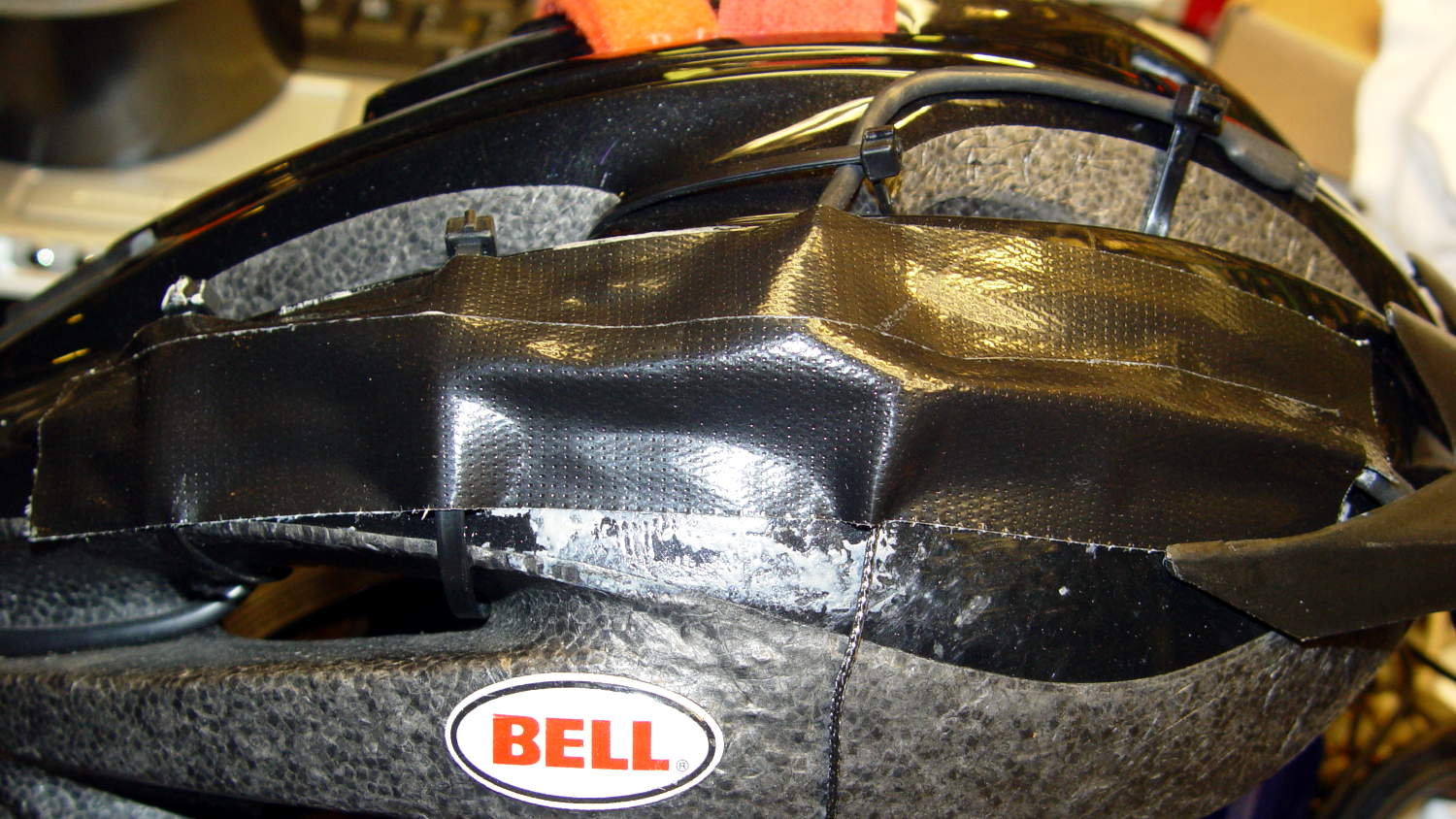
The motivation for all this was having the Gorilla Tape peel off the helmet, leaving a hardened mass of glue behind, then snagging the earbud wires. This is the new, somewhat better protected, wiring:
Bell Helmet – mic-earbud wire – hardened tape adhesive
In a triumph of hope over experience, I applied more Gorilla Tape:
Bell Helmet – re-taped mic-earbud wiring
The helmet may need replacing after another iteration or two.
My solid modeling hand has become stronger these days, so I should gimmick up a flat-ish wart anchoring the mic boom and all the wiring to the helmet shell.
While installing Mint on the Lenovo Q150, I discovered that the right button on the (long disused) Logitech M305 wireless mouse wasn’t working. After replacing the batteries (always check the batteries), it still didn’t work, so I peeled the four slippery feet off the bottom, removed the screws, and confronted the interior:
Logitech M305 mouse – interior
Much to my surprise, the button switches had removable covers:
Logitech M305 mouse – switch disassembly
I put a minute drop of DeoxIT Red on a slip of paper, ran it between both pairs of contacts, removed a considerable amount of tarnish, reassembled in reverse order, and it’s all good again.
The glue on the back of the slippery feet didn’t like being peeled off, so I expect they’ll fall off at some point.
It’s much easier to drive a GUI with three functional buttons…
[Update: Long-time commenter Raj notes:
I always had problem with the middle button. I have replaced them a few times and learnt that they come with different operating pressures. The soft ones are hard to come by. I found an alternate in the PTT switches on Yaesu handies in my junk.
That’s the blocky switch to the left of the shapely wheel cutout.]
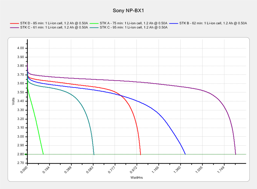
After 95 minutes on a pleasant ride with temperature around 55 °F, the STK C battery had 0.59 W·h remaining (dark green trace):
Sony NP-BX1 – STK used – Wh scale – 2015-12-12
The last time around, it had 1.85 W·h after 61 minutes. Subtracting the two (and ignoring that it may have started with slightly different charges and behave differently at different temperatures) says the camera used 1.26 W·h = 76 W·min in 34 minutes, which averages out to 2.2 W.
That’s close enough to the “a bit over 2 W” figured from those partial-to-empty measurements for me.
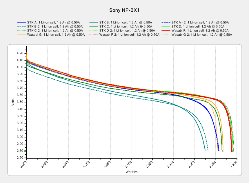
The best STK battery (D) holds just under 4.2 A·h, so its absolute longest run time could be 110-ish minutes. That graph shows the A cell was just about done after 75 minutes, so changing the battery after an hour still makes sense; you never know what will happen during the last few minutes of a ride…