Ed Nisley's Blog: Shop notes, electronics, firmware, machinery, 3D printing, laser cuttery, and curiosities. Contents: 100% human thinking, 0% AI slop.
A SquidWrench meeting discussion about printing transparent objects prompted me to conjure a soap dish from the vasty digital deep:
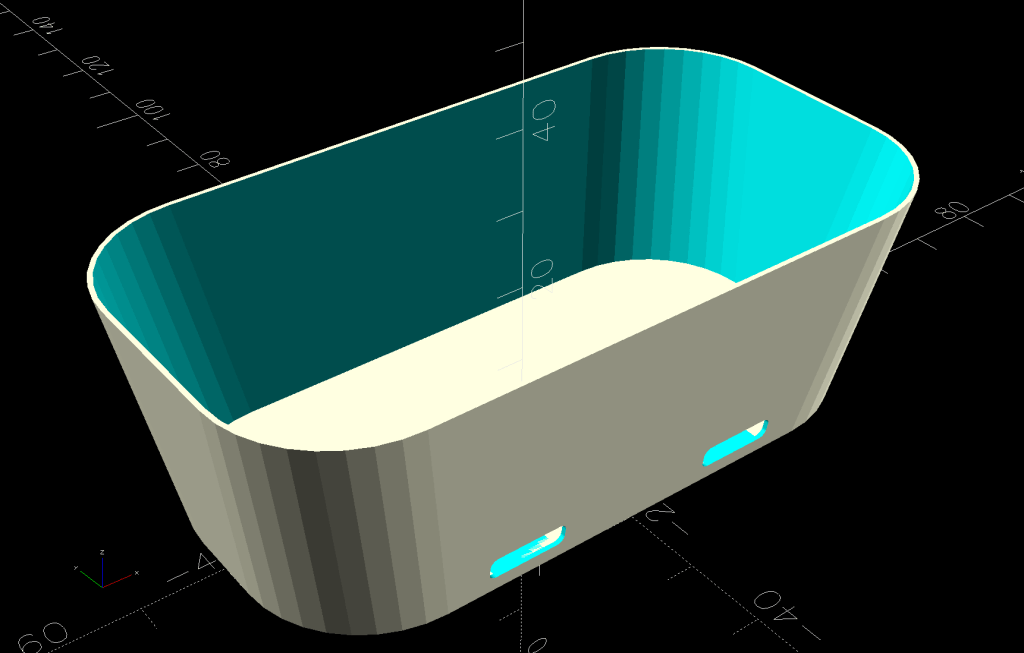
Shower Soap Dish – solid model
They’re all done in “natural” PETG with sufficient variations in speed, temperature, extrusion multiplier, and fill pattern to stock the shower & tub:
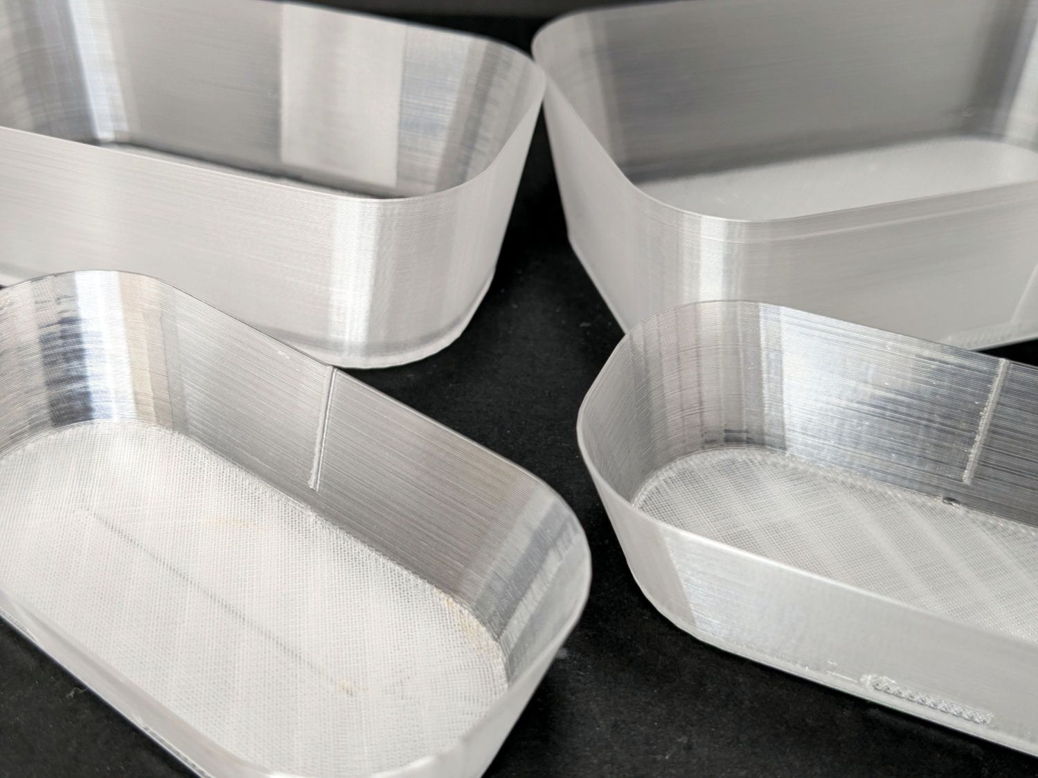
Translucent soap dishes
The single-thread sidewalls came out reasonably translucent in all the variations, but the baseplate remained stubbornly white-ish, even at 20 mm/s and 250 °C with 100% infill. The seams where the extruder retracts and lifts to the next layer remain conspicuous, with a scarf joint forming the white slab in the left-rear dish.
Quite a while ago, I’d considered making soap dishes with shattered-glass bottoms, but came to my senses. These have some key advantages:
Exactly the right size for narrow shower shelves
Light enough to not damage anything when it inevitably falls off
Reasonably unbreakable when that happens
Easily replaced
They’re also test pieces for the whole transparency thing, so it’s all good.
This file contains hidden or bidirectional Unicode text that may be interpreted or compiled differently than what appears below. To review, open the file in an editor that reveals hidden Unicode characters.
Learn more about bidirectional Unicode characters
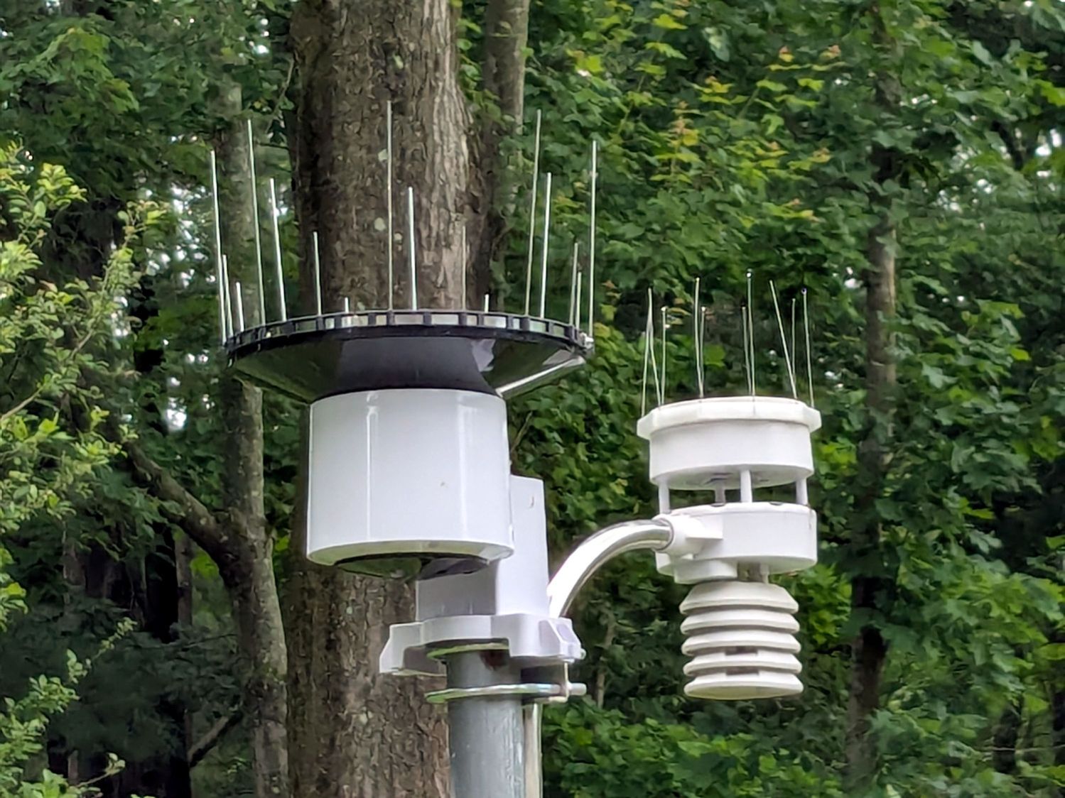
Chickadees can perch between the wires and squirrels apparently just ignore the sharp ends:
Squirrel on WS-5000 Anemometer spikes
No matter how hard that squirrel looked, there were no nuts to be found anywhere in that tree. Moments later it ran down the pole and loped across the yard to forage under the seed feeder.
The terrible picture quality comes from a Pixel 6a phone camera zoomed all the way tight. I want an optical telephoto lens built into the phone, but those phones seem intended to reduce the risks of having severe wallet overpressure.
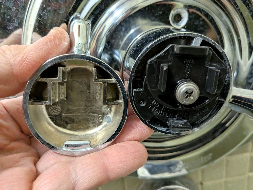
As a reminder for the next time in this rodeo, the latches holding the temperature adjustment knob on the Delta 17 Series dual-handle bath / shower faucet look like this:
Delta bath faucet cap latches
I am unable to apply enough force to the smooth edge of the knob opposite the handle to un-latch it, so I jammed a small prydriver into the gap and twisted enough to pop the latch, at the obvious risk of scarring the chrome plating.
A better approach would involve a plastic prydriver intended for consumer electronics case cracking.
For the record:
Unlike the other bath faucets, this one has shutoff valves inside the wall
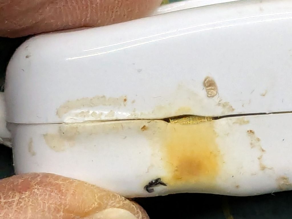
One of the inline switches I installed to replace the failed switches for the LED lights got unpleasantly warm enough to prompt an investigation:
Inline lamp switch – heat damage
Yeah, that is not a nominal outcome, particularly in light of the claimed “10 A 250 V” rating.
The overheated plastic pulled back enough to expose the terminal inside:
Inline lamp switch – visible terminal
There was a reason I’d wrapped those switches with known-good 3M electrical tape before deploying them.
That crimp connector took some heat and its screw looks even more unhappy:
Inline lamp switch – internal damage
It turned out the screw was an itsy too short to compress both the connector and the bent-metal conductor tab against the terminal block:
Inline lamp switch – misfit screw terminal
A 6 mm brass screw with a brass washer did a better job of compressing all parties into one conductive lump.
Although the switch now runs with the case at normal basement temperature, an allegedly UL listed replacement is on its way; it costs about five times more than that switch. If it behaves as it should, I’ll preemptively replace two other switches.
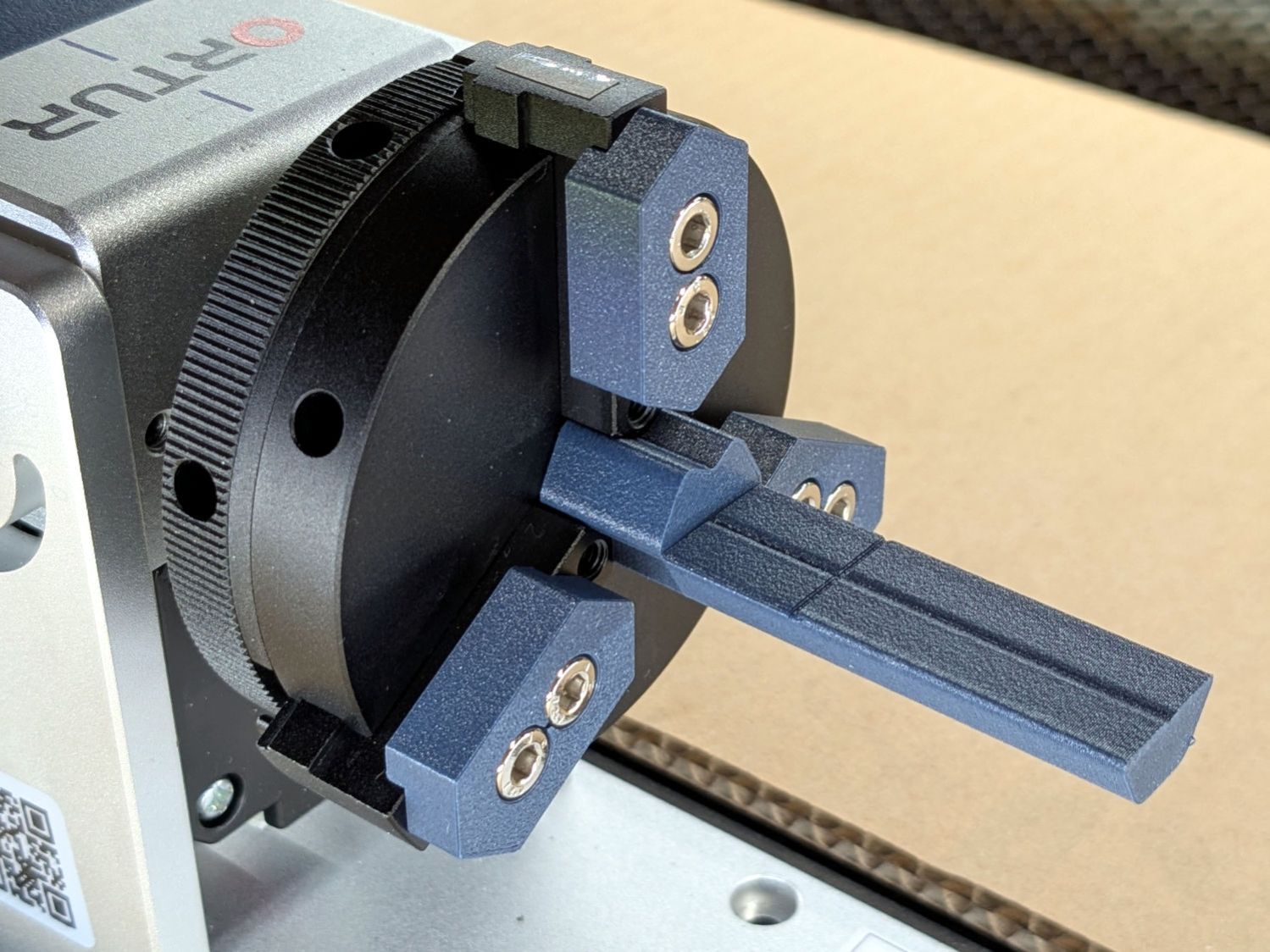
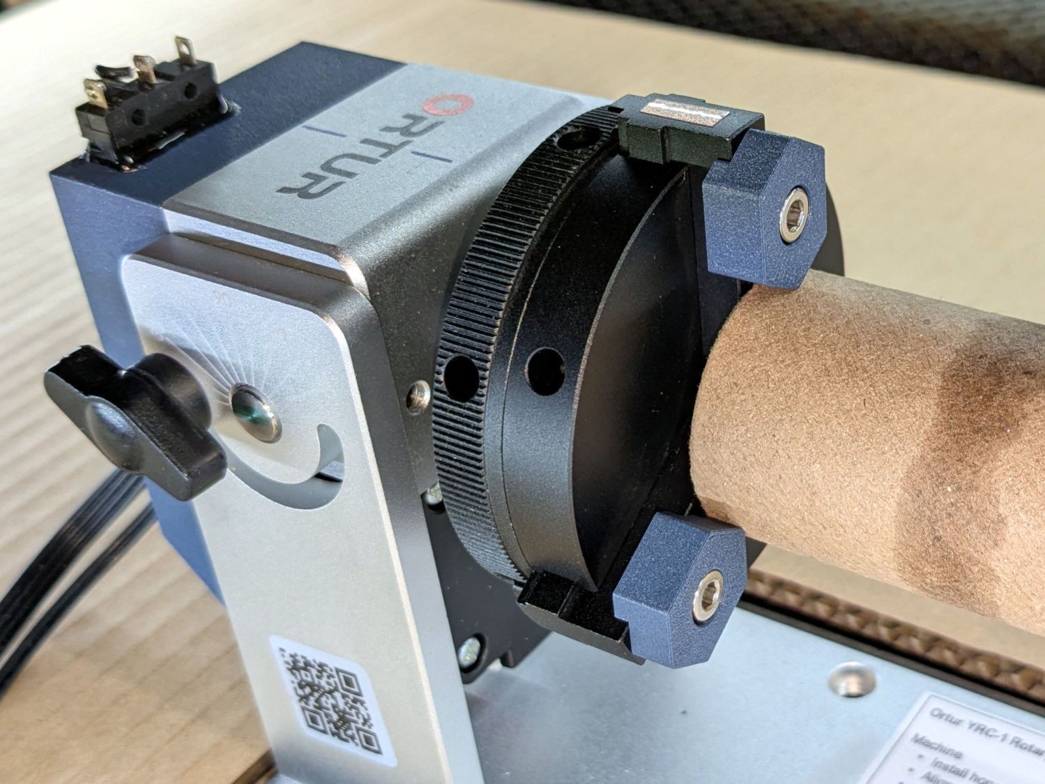
The standard jaws for the Ortur Rotary loom over small-diameter workpieces:
Ortur Rotary Focus Pad – home offset adjustment
Some measuring and modeling produced petite 3D printed jaws:
Ortur Rotary – printed jaws
Admittedly, those jaws aren’t doing much of anything, but they’re not nearly as much in the way. You (well, I) can screw them in closer to the center to overlap the chuck jaws or another hole outward for slightly larger cylinders.
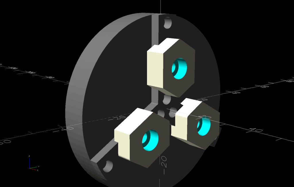
The solid model looks about the same:
Ortur Rotary Jaws – 2-3 show view
They build face-down with a little support under the screw recesses for a clean fit on the chuck:
Ortur Rotary Jaws – Prusaslicer
Teeny jaws might be handy:
Ortur Rotary Jaws – 2-2 show view
Screwing them in one hole outward lets them grip medium cylinders without sticking out from the chuck jaws:
Ortur Rotary – small printed jaws
The OpenSCAD code lets you pick which screw holes you want, but it does not error-check the perverse choices.
This file contains hidden or bidirectional Unicode text that may be interpreted or compiled differently than what appears below. To review, open the file in an editor that reveals hidden Unicode characters.
Learn more about bidirectional Unicode characters
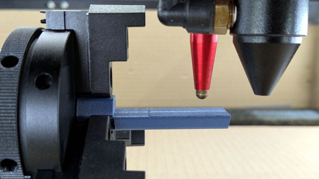
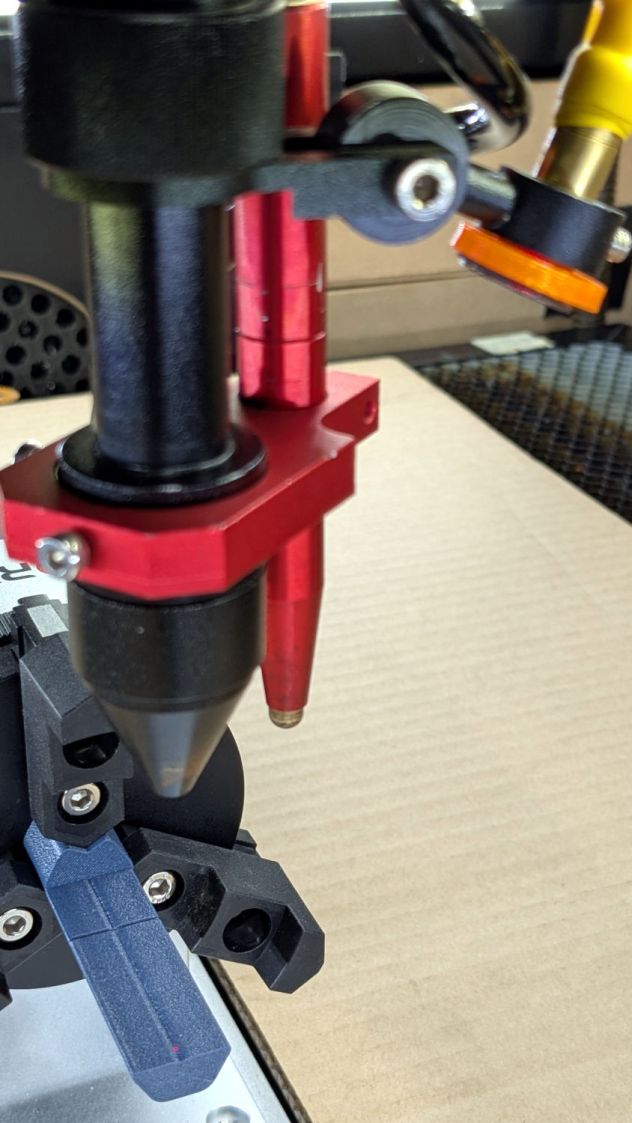
Ruida laser controllers do not allow the platform to rise above the U=0 origin set by the autofocus pen = switch. While this isn’t a problem for flat surfaces, focusing on the exact top of a horizontal cylinder, particularly a small rod, may be overly difficult.
So a focusing pad seems like a Good Idea™:
Ortur Rotary Focus Pad – focus pen positioning
The general idea:
Align a flat horizontal surface with the rotary chuck’s axis
Do the autofocus operation with a well-defined landing zone under the pen
Jogging the head upward (= platform downward) by the workpiece radius puts the focused spot exactly at the right height
Remove the focus pad
Install the workpiece
Fire The Laser
The solid model:
Ortur Rotary Focus Pad – solid model
Features of note:
The chuck jaws fit into the recesses on the left end for a firm grip with good alignment
The lengthwise notch lies on the rotary axis parallel to the laser’s X axis
The crosswise notch is juuust rightward of the chuck jaws, marking the leftmost end of whatever you’re engraving
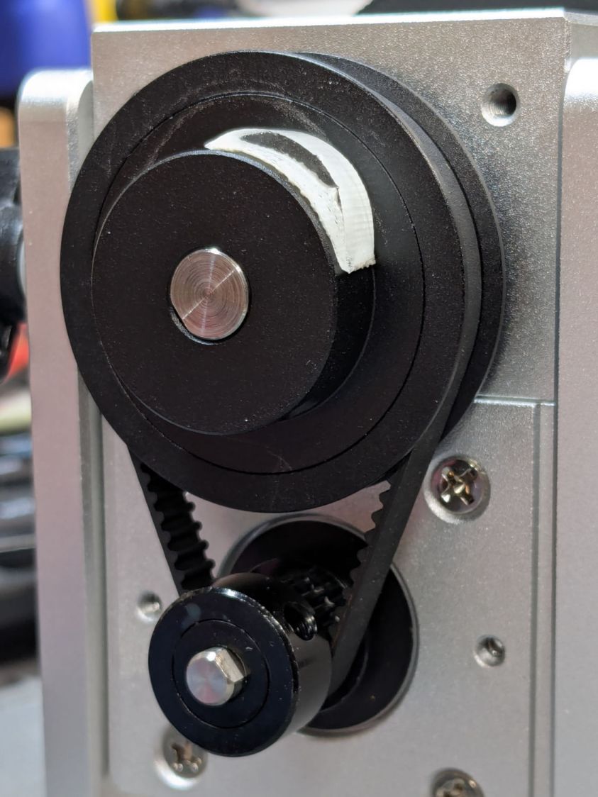
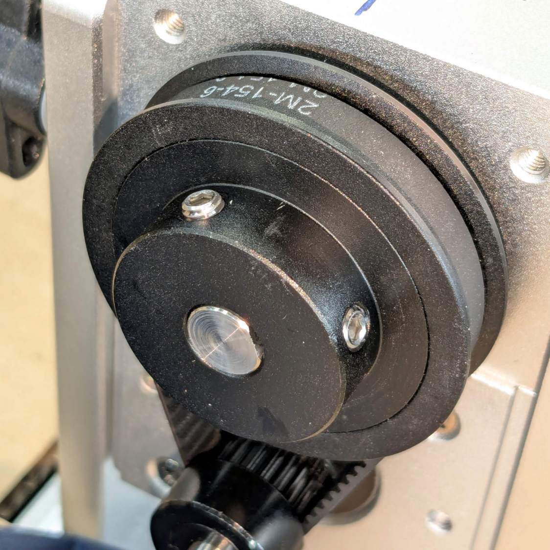
Because I added a home switch to the Ortur YRC-1 case, Jaw 1 automagically ends up on top after homing, thus automagically making the focus pad horizontal. Getting that right required fine-tuning the rotary’s home switch trip point, which turned out to be easier to do using the Home Offset configuration value after I replaced the cam I thought would work:
Ortur Chuck Rotary home switch – pulley cam
Instead, a simple M4 setscrew (standing proud of the pulley surface in one of the tapped holes for the real setscrew securing the pulley to the shaft) trips the switch much more repeatably :
Ortur Rotary Focus Pad – home trip setscrew
The setscrew on the right sits flush with the surface to prevent the switch roller from falling into the hole. The real setscrew underneath it locks the pulley to the shaft’s flat.
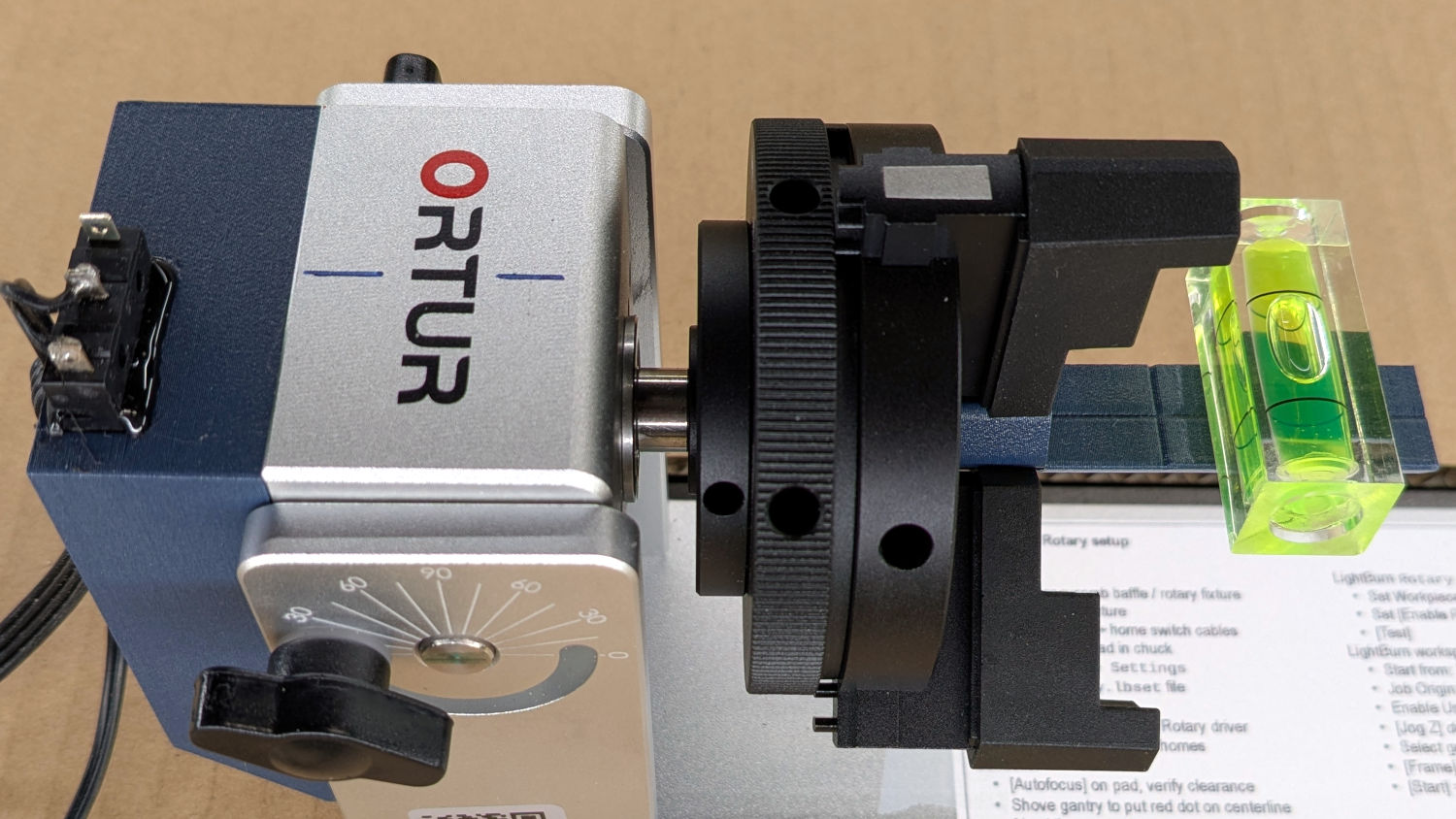
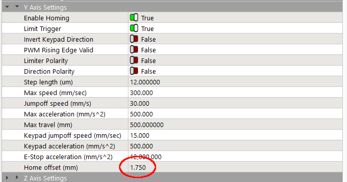
With that in place, a quick binary search settled on a Y axis Home Offset = 1.75 mm to put the pad level with the top of the rotary’s case, which is Level Enough™ due to my tweaking the machine’s foot elevations after jacking the whole machine up on risers:
Ortur Rotary Focus Pad – home offset adjustment
The Home Offset value:
The speed and acceleration values are much lower than used with the linear Y axis, because apparently Ruida computes the corresponding step values using the workpiece diameter in the Rotary section. Small diameters produce impossibly fast motions, which suggests they expect you to set the optimum values based on back-calculations from the object diameter; ain’t nobody got time for that.
Anyhow.
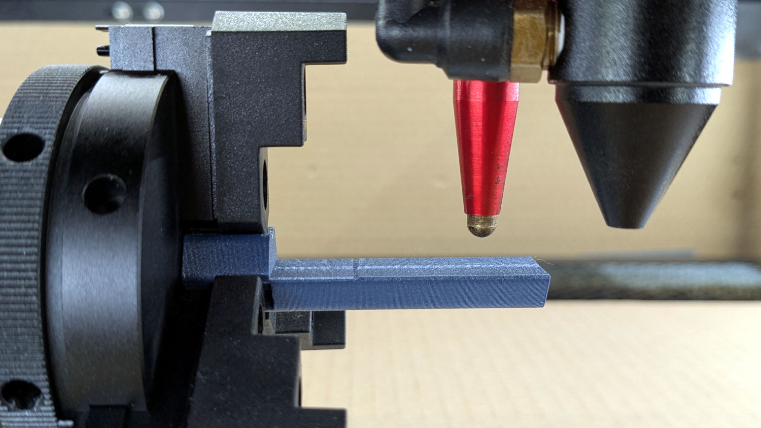
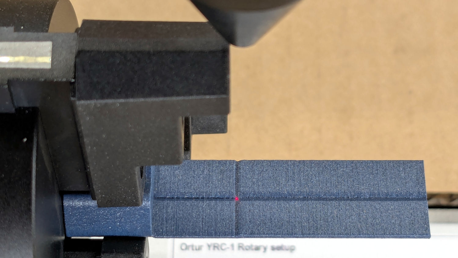
After autofocusing, the red-dot pointer now indicates the laser spot position, so jog the X axis and drag the gantry to put the spot on the axis mark:
Then jog the X axis to put the dot at the transverse mark just beyond the chuck jaws:
Ortur Rotary Focus Pad – red dot at origin
Hit the Ruida Origin button to set that as the user origin, so you can reference the LightBurn design to the hardware position.
Move the platform down by the workpiece radius, jog the nozzle along the X axis to get it out of the way, remove the focus pad, install the workpiece, and you’re good to go. The checklist visible beyond the bubble level shows it’s not quite that simple, but we’re getting there.
This file contains hidden or bidirectional Unicode text that may be interpreted or compiled differently than what appears below. To review, open the file in an editor that reveals hidden Unicode characters.
Learn more about bidirectional Unicode characters
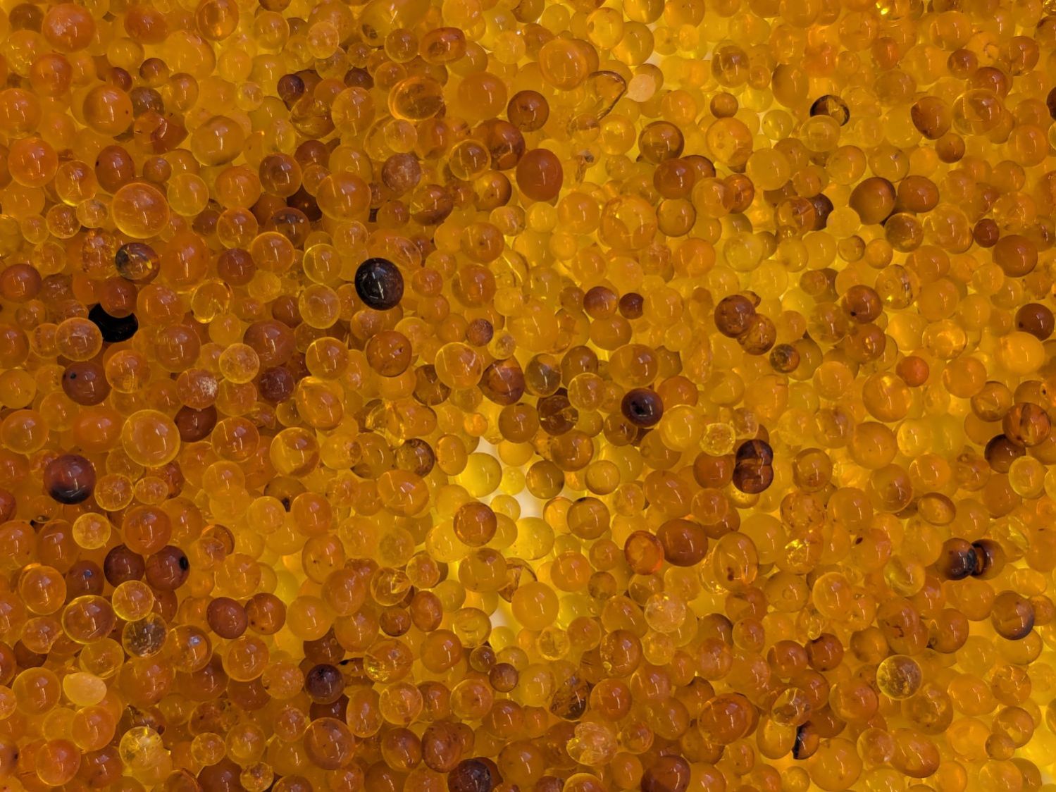
The humidity indicating chemical seems to be methyl violet, described as changing from yellow to green when saturated, which has never happened here. For example, these beads, retrieved from random corners of the workbench, have been sitting in 40-ish %RH basement air for weeks:
Silica gel beads – 36pctRH ambient
The fragment just left of center looks greenish, but the rest are, at best, various shades of brown. This may be due to the (relatively) low humidity in the basement, but putting them under a damp sponge for a few hours didn’t change their color.
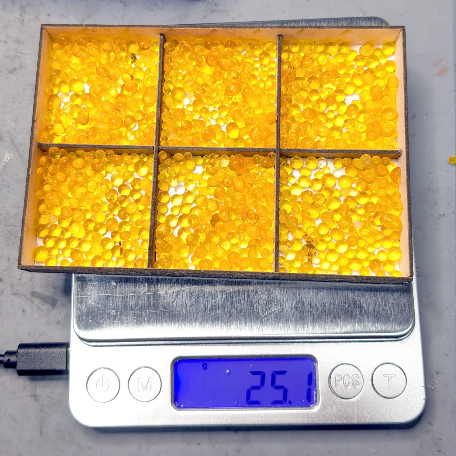
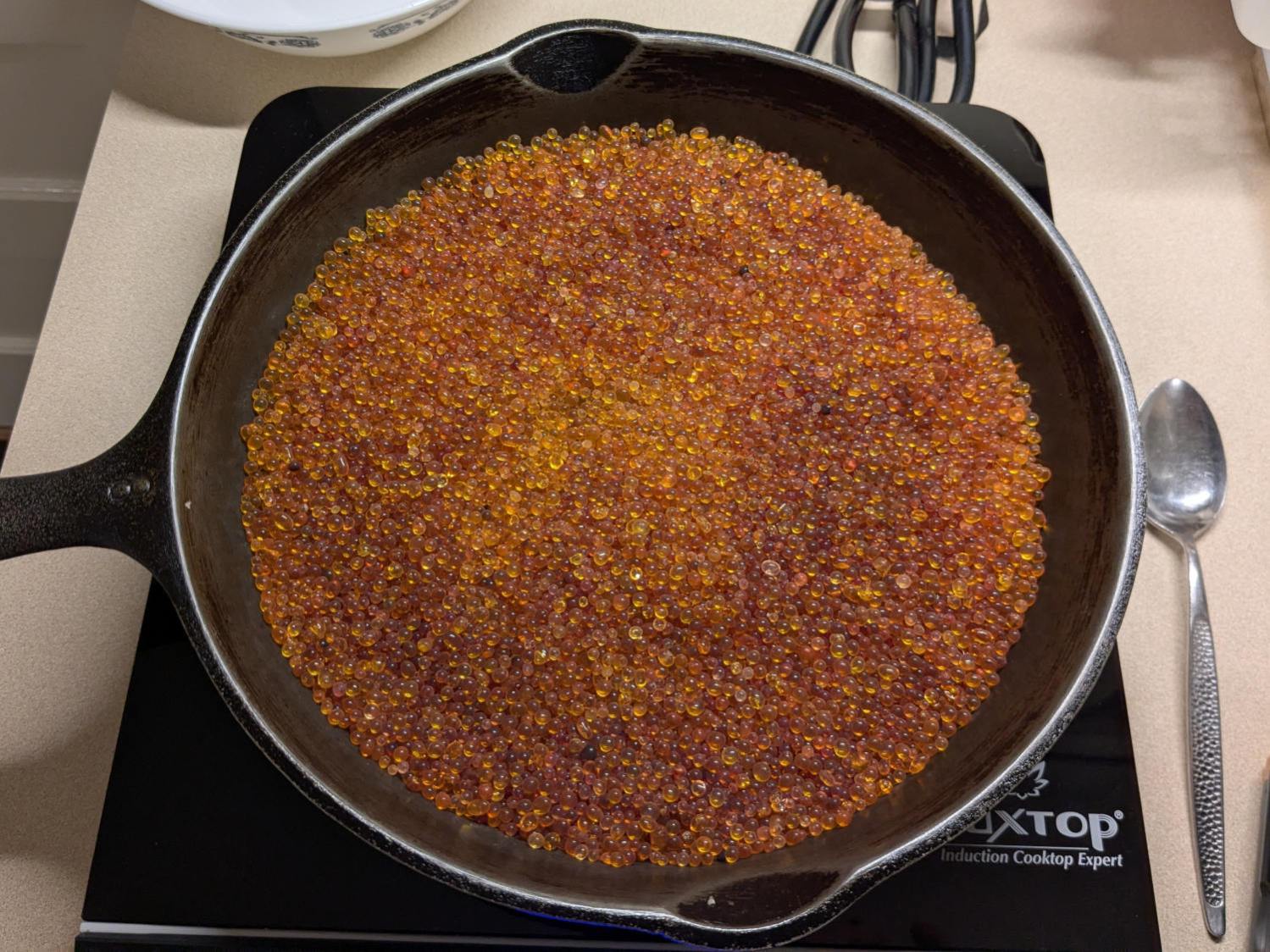
The most recent regeneration session started with an open cast-iron pan on an induction cooktop:
Silica gel beads – drying
The variety of browns comes from various amounts of adsorbed water in the PolyDryer boxes, but AFAICT there really isn’t much correlation between the humidity level and the amount of adsorbed water.
The drying process went like this:
650 g at start
50% power for 2 hr → 200 °F
Covered the pan & turned it off overnight
623 g at start
50% power for 2 hr → 220 °F
612 g
50% power for 1 hr → 236 °F
610 g
30% power for 30 min → 205 °F
35% power for 30 min → 200 °F
609 g
So about four hours at 50% power would get all but the laser few grams of water out of the silica gel.
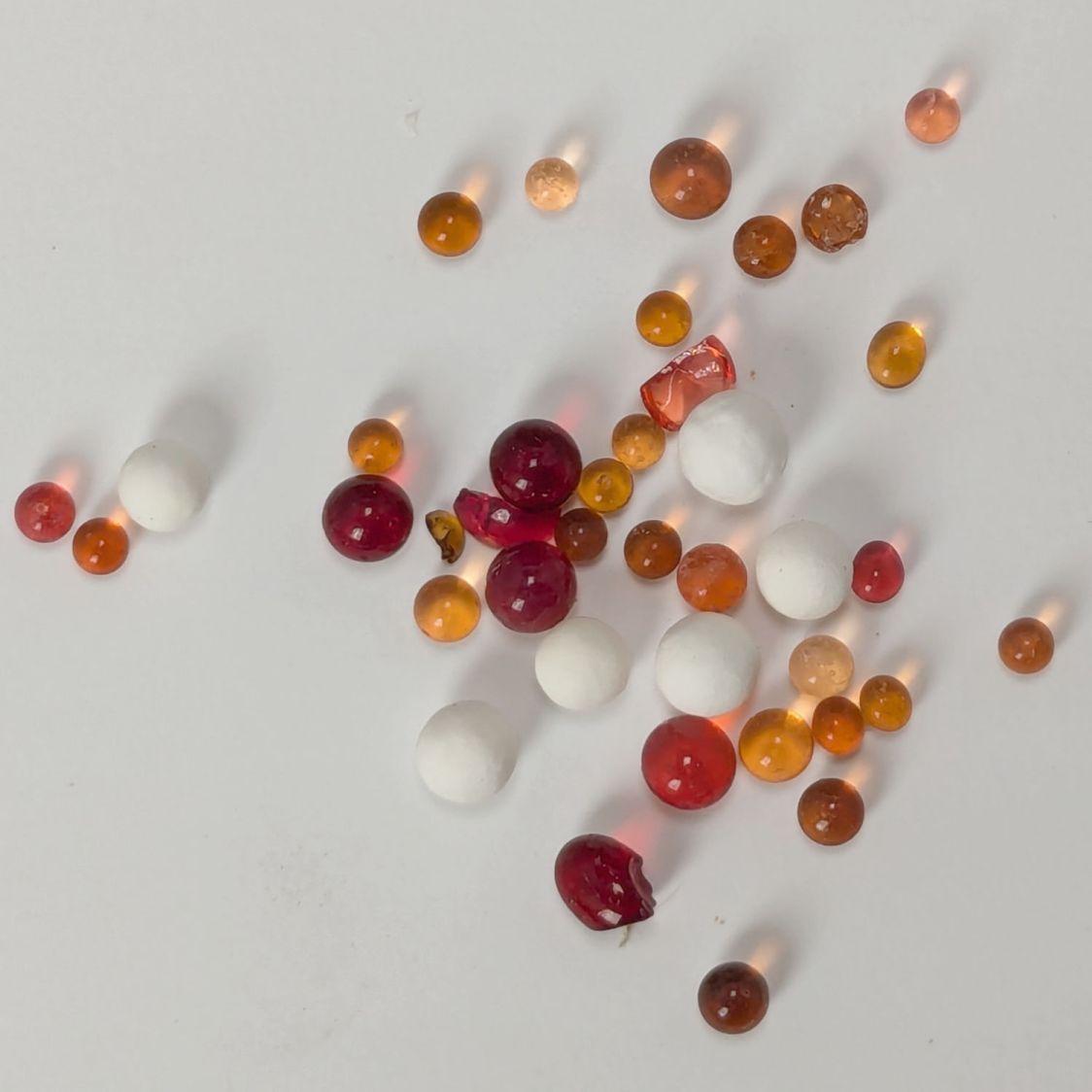
After all that, the beads looked about the same in a white bowl for cooling:
Silica gel beads – damaged indicator dye
Each regeneration cycle leaves more dark brown beads in the mix, which may be due to poor temperature control, and they do not return to their original yellow / pale brown shade.
Apparently cooking silica gel beads over 120 °C = 250 °F (various sources give various temperatures) can damage their structure or the methyl violet indicator; for sure some of those beads have been abused.
Unsurprisingly, the bead temperature rises as they dry out. Although the induction cooktop has a temperature control, we’ve found the setting doesn’t match the pan temperature and the overall control is poor. I could set the gas oven to 200 °F, but I’m certain it doesn’t control the temperature all that closely, either.
The original jug held 2 pounds = 907 g of beads. Add the 609 g from this session to the 350 g of allegedly dry beads in seven of the PolyDryer boxes: my regeneration hand is weak.