The Smell of Molten Projects in the Morning

Ed Nisley's Blog: Shop notes, electronics, firmware, machinery, 3D printing, laser cuttery, and curiosities. Contents: 100% human thinking, 0% AI slop.

Author: Ed

  • Garage Opener Antenna Director

    Garage Opener Antenna Director

    By a quirk of fate, the Chamberlain garage door opener in our new house has the same “purple learn button” as the Sears opener in our old house, so I introduced it to our remotes and they work just fine.

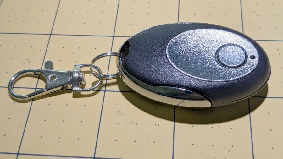
    I then replaced the four-button remote in my bike pack with a new single-button remote to reduce the dexterity required to hit the button:

    Garage Opener - one button
    Garage Opener – one button

    Alas, the opener only responded when the remote was immediately outside the aluminum garage door. Checking the battery (because sometimes “new” does not mean what you think it means) reminded me we live in an age when hardware is free compared with bookkeeping:

    Garage Opener - interior
    Garage Opener – interior

    Maybe the second button doesn’t work and this is how they monetize their QC reject pile?

    I want the door to start moving when I’m at the end of the driveway, giving it enough time to get all the way up so I can bike right in. You can actually buy remote / extension antennas, although for fancier openers with SMA antenna connectors, but sometimes a little RF black magic will suffice:

    Garage Opener - crude antenna director
    Garage Opener – crude antenna director

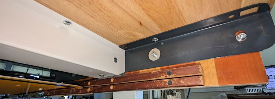
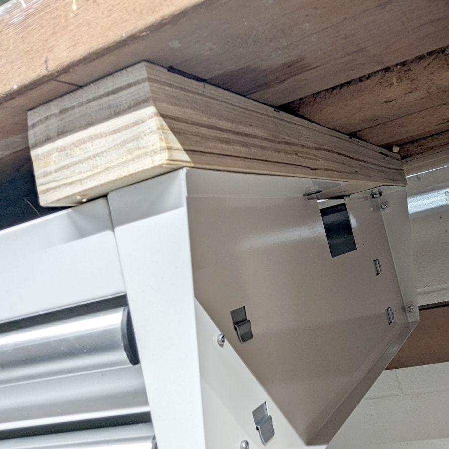
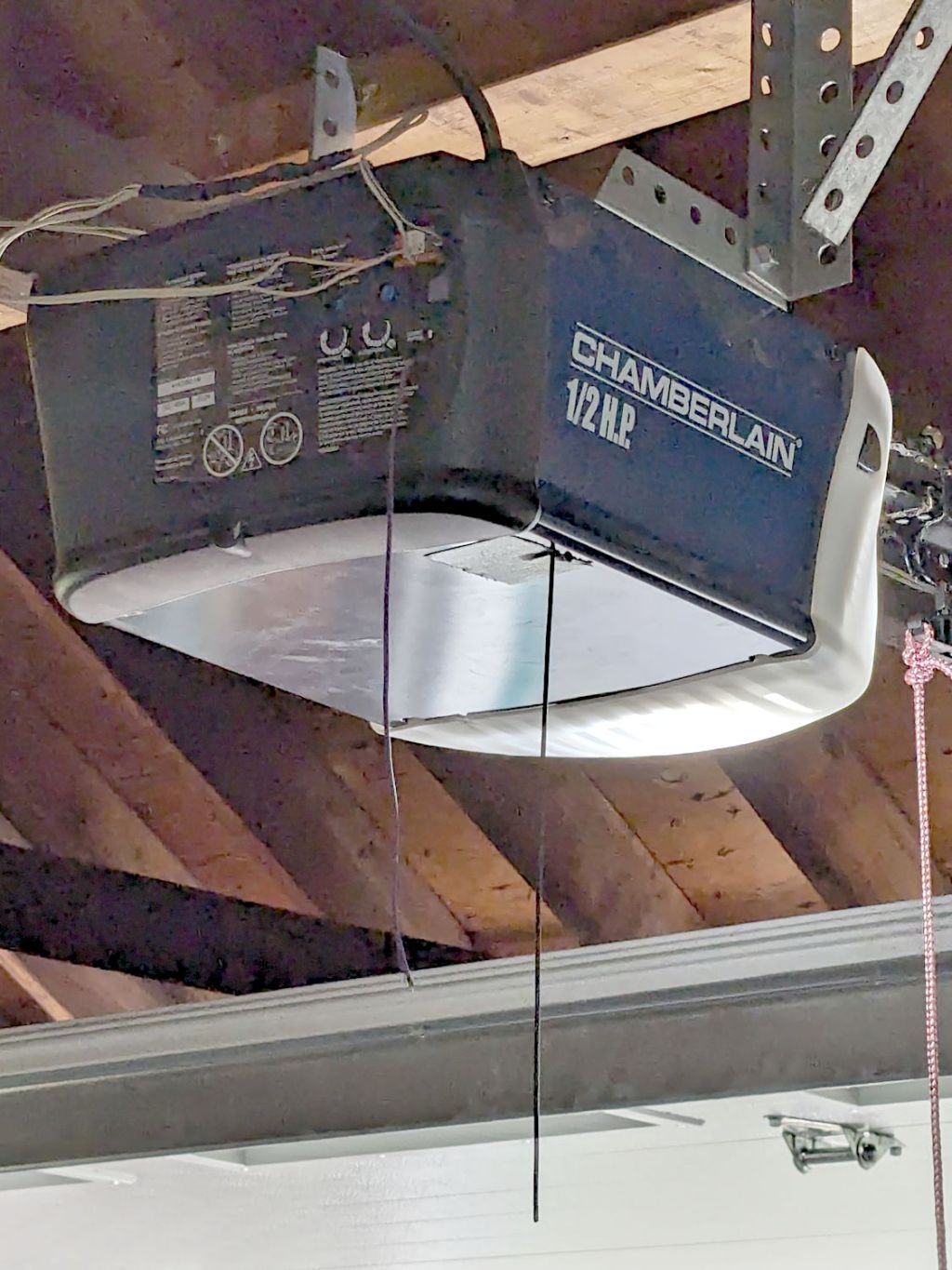
    The wavy wire hanging down from the opener’s rear panel is the original antenna, which might be kinda-sorta omnidirectional. The opener operates around 433 MHz= 69 cm, so a quarter-wave antenna will be 17 cm = 7 inch long; the (unbent) wire is maybe 10 inches long from the hole in the panel.

    So I taped 11 inches of wire to the opener to form a very very crude Yagi-Uda antenna. It’s too long to be a director element, it’s about right (albeit in the wrong place) to be a reflector element, it might be neither.

    What it does do is warp the antenna’s pattern just enough to let the remote reliably trigger the opener as I approach the end of the driveway.

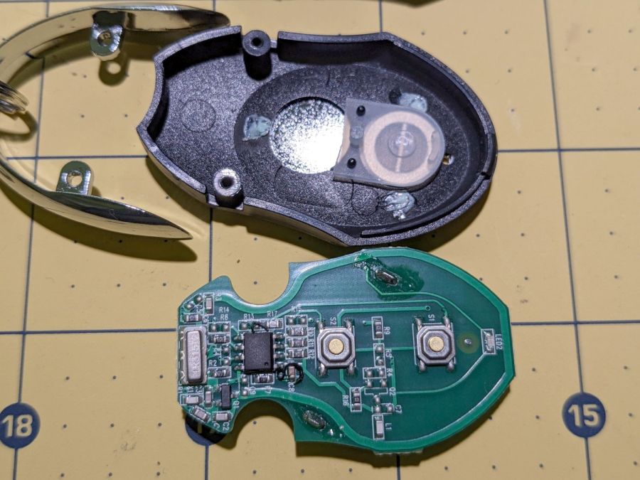
    Do not even begin to think about polarization mismatch from what looks like the tiny loop antenna on the remote’s PCB.

  • Kenmore Microwave Turntable Drive Rollers

    Kenmore Microwave Turntable Drive Rollers

    Our ancient Kenmore microwave has a three-armed turntable drive:

    Kenmore Microwave - turntable installed
    Kenmore Microwave – turntable installed

    After all these years the (white) rollers have worn to the extent they fall off the (brown) drive arms all too easily. They ride in a recessed track in the glass plate that holds them in place during normal operation, but having once again found a roller wandering around when I put the turntable back in, it’s time for at least a temporary fix.

    Everything is, of course, plastic:

    Kenmore Microwave - turntable drive roller parts
    Kenmore Microwave – turntable drive roller parts

    I considered drilling the end of the axle and tapping it for a nylon screw + washer, but came to my senses just in time:

    Kenmore Microwave - turntable drive
    Kenmore Microwave – turntable drive

    The laser-cut parchment paper disk (barely) fits over the axle against the outside of the roller, while allowing the hot-melt glue to glom onto the undercut and hold everything in place:

    Kenmore Microwave - roller glopped
    Kenmore Microwave – roller glopped

    I expect the paper to wear / fall off in short order, but the HDPE roller won’t bind against the glue and the blob should remain latched in place for a while.

    When those hideous glue blobs do fall off, I’ll reconsider drilling & tapping. More likely, I’ll just fire up the glue gun again.

    Actual use required trimming the blob from the upper side of the roller / hub, because the track in the glass plate fits very close against the edge of the roller. The hideous glue blob slid freely on the roller, but jammed firmly against the plate, causing it to turn at half speed.

  • Workbench Drawers vs. Desk Keyboard Tray

    Workbench Drawers vs. Desk Keyboard Tray

    The workbench originally in Mary’s Sewing Room became my new desk, which meant installing my pull-out keyboard / trackball tray in place of its drawers:

    Desk keyboard tray - top view
    Desk keyboard tray – top view

    Which required re-gluing the old wood strips of the side slides to their backing plates, as they’d worked loose over the decades:

    Desk keyboard tray - regluing edge sliders
    Desk keyboard tray – regluing edge sliders

    I drilled & screwed three more threaded wood inserts into the bottom of the bench top to hold brackets (cut from those longsuffering maple library shelves) for the side slides:

    Desk keyboard tray - bottom view
    Desk keyboard tray – bottom view

    The gray angle brackets came from a long-gone (and sorely missed) radial arm saw, hacksawed to fit on either side of the central beam supporting the workbench top, and held with machine screws in those inserts. Yes, the rear bracket has only a single screw, but it doesn’t support much of a load and it’s not going anywhere.

    With that in place, the drawers kicked around the basement for a few weeks and eventually ended up under a workbench that Came With The House™ and was likely built by the original owners half a century ago:

    Desk keyboard tray - workbench drawers installed
    Desk keyboard tray – workbench drawers installed

    The top is made of 2×6 boards, now topped with laminate planks (left over from when I re-floored the previous kitchen), so the 2×6 board in the middle holds the whole top together and is not removable. I conjured strips at the ends to support the drawer assembly:

    Desk keyboard tray - workbench drawers end block
    Desk keyboard tray – workbench drawers end block

    The strips came from the crate around the laser cutter, so they’re made of the cheapest Chinese plywood and entirely suitable for the purpose. The drawers hang from 1/4-20 bolts screwed into tee nuts recessed in the top surface of the strips, with the strips held by deck screws in those benchtop 2×6 planks.

    Yeah, both of those are bodges, but they ought to work just fine.

  • Laser Cutter: Test Cuts

    Laser Cutter: Test Cuts

    Just to see if all the laser parts once again fly in formation, I cut a defunct cotton shirt into shop wipes:

    Laser cutter - first cuts after move
    Laser cutter – first cuts after move

    Which worked as before:

    Laser cutter - more wipes
    Laser cutter – more wipes

    Not that I need more wipes, but in this case the process is more important than the product.

    Looks like I can start using the laser cutter again … whew!

  • Laser Cutter Alignment Check

    Laser Cutter Alignment Check

    A couple of test shots to verify the move hasn’t jostled the laser mirrors too far out of alignment:

    Laser cutter alignment check
    Laser cutter alignment check

    The overlapping scorches on the left happened at the Mirror 3 position with the laser head at the far left and near right positions. Not quite as accurate as immediately after I overhauled the beamline, but close enough.

    The pair of dot + disk scorches on the right show the beam position on the platform at the focus point and 20 mm below. The red-dot pointer definitely traces a wavering path as the platform goes down, suggesting the leadscrews may have taken a sideways jolt during the laser’s trip down the basement stairs and are now distinctly angled in their guides, but it’s good enough for my simple needs.

    Looks like the laser survived the move pretty much intact!

  • OMTech Laser Cutter: Honeycomb Rivnut

    OMTech Laser Cutter: Honeycomb Rivnut

    The honeycomb platform in my OMTech laser cutter was secured by a pair of M4 screws passing through the surrounding frame into a pair of nuts requiring considerable contortion to install. As a result, I tended to use the screws as locating pins by just dropping them into the holes, which didn’t prevent me from jostling the honeycomb out of position on a few occasions.

    With everything torn down as part of the move, I drilled out the holes in the frame and installed a pair of M4 rivnuts:

    OMTech laser - Honeycomb screw rivnut
    OMTech laser – Honeycomb screw rivnut

    The scar around the hole in the honeycomb came from the factory; I have no idea what they were doing to cause that much wear.

    Anyhow, installing the screws now requires zero contortionism and they locate the honeycomb much more securely.

    I should conjure knobs for the top of the screws to eliminate the need for a hex key, although that’s definitely low on the task priority list.

    Update: Like this:

    Honeycomb screw knob
    Honeycomb screw knob
  • Laser Water Chiller: Heating

    Laser Water Chiller: Heating

    The previous Basement Laboratory generally stayed above 60 °F = 15 °C, so I set the LightObject water chiller’s low-temperature alarm accordingly.

    Having reached the point where I can set up the laser in its new home, I connected the chiller tubes, filled the reservoir with distilled water (and a squirt of algaecide), connected the alarm wiring, turned it on, and had the cool water trigger an alarm:

    LightObject Laser chiller - low temp alarm
    LightObject Laser chiller – low temp alarm

    Which was relayed to the controller:

    KT332N Diagnostic display - water protect active
    KT332N Diagnostic display – water protect active

    Silencing the chiller’s alarm clears the error indicator in the controller, so it’s possible to Fire The Laser with too-cold water if necessary.

    As with the previous icemaker chiller, plotting the water temperature as a function of time shows the pump adds some energy as it moves the water around the loop:

    LightObject Q600 chiller - water heating
    LightObject Q600 chiller – water heating

    The gap in the data shows where I had a few other things to do, but the exponential rise is obvious. The chiller compressor starts at just over 21 °C and stops at just under 20 °C, so the exponential curve had gone about as far as it could go.

    The numbers in the upper right of the plot give the weight of:

    • An empty water bottle
    • A full gallon bottle
    • The partially empty bottle used to top off the reservoir
    • How much water went into the chiller reservoir

    The figures in the bottom mash the initial slope of that curve together with the weight of the water to find the 21 W required to heat the water at that rate, with a bank shot off British Thermal Units because why not.

    A Kill-a-Watt meter shows the Q600 chiller draws 36 W with the pump running, which includes the controller and a column of blue LEDs behind the water level tube.

    The pump (in the lower right) isn’t exactly water-cooled, but it’s not losing a lot of heat through that foam wrapper and maybe most of the heat really does come from the motor:

    LightObject Laser chiller - right side internal view
    LightObject Laser chiller – right side internal view

    The basement temperature will rise as Spring becomes Summer, so the chiller will start working right away, and it’ll definitely get more exercise when the laser starts cutting again.