Ed Nisley's Blog: Shop notes, electronics, firmware, machinery, 3D printing, laser cuttery, and curiosities. Contents: 100% human thinking, 0% AI slop.
When the second hinge on my father-in-law’s scanner broke, he asked if I could fix it:
HP3970 Scanjet Lid – broken hinge
It’s a flatbed scanner, so the lid is nearly 18 inches long and weighs 2.2 pounds with the slide / negative backlight illuminator. The stress raiser notches, located exactly where the cracks started, look like a perfect example of how not to do these things.
I solvent-glued the hinges back together, with a square brass tube applying clamping force to the joint overnight, but this certainly won’t last for long:
HP3970 Scanjet Lid – crude repair
HP used to have some really smart engineers, but this looks like it was done by a Newkid (I was one, once, so I know the type) after a solid modeling and simulation session convinced him that those two thin plastic webs had enough strength for the job.
No. They. Do. Not.
Of course, HP provides no Official Way to repair that failure, as the hinges emerge seamlessly from the injection-molded plastic lid frame: you must scrap the scanner and buy a new one, because the lid would cost more than a new scanner. Equally of course, the fact that they don’t have a Windows driver beyond XP makes replacement a foregone conclusion.
It runs under Xubuntu 12.04, mostly, which is what I set him up with after the XP PC got compromised.
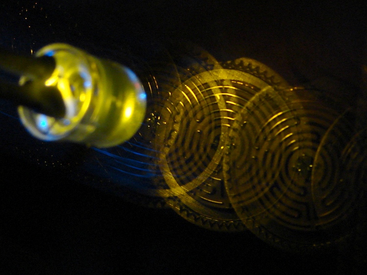
A bit of fiddling with the Arduino PWM hardware can turn a white LED into a stroboscopic tachometer to chop smooth motion into chunks:
Strobe – Maze 1 – 50 Hz 100 us
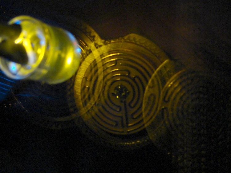
I was moving that pendant by hand and slight speed changes were easily visible:
Strobe – Maze 2 – 50 Hz 100 us
IBMers of a certain era may recognize the test object; the rest of you can go there.
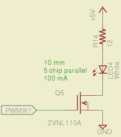
That’s a 10 mm warm-white LED with 5 parallel chips, running at about 100 mA from a 5 V supply, and driven from the same PWM channel and MOSFET that used to drive also drives the red channel of the RGB LED Mood Light:
White LED Strobe
The ZVNL110A MOSFET has a 3 Ω drain resistance, which becomes a significant part of the resistance; you’d want a bigger, better, lower resistance MOSFET to wring more light out of the LED. In fact, I ran the LED from 12 V with the same resistor at a few hundred mA.
The reason you need more light is to make up for the minuscule duty cycle. In order to “stop motion”, you want a very short pulse; I picked a 100 μs pulse. At 50 Hz, that works out to a 0.5% duty cycle: not much light at 100 mA, but OK for a demo.
You can’t do this with the standard Arduino PWM setup, because it produces a constant frequency (about 488 Hz) and varies the duty cycle; we need a variable frequency with a constant pulse length. Because a stroboscope needs fine-grained control over the frequency, in order to stop the motion of rotating objects, it should run from one of the 16 bit Timer1 PWM outputs, which means either PWM9 or PWM10. Note that simply changing the timer’s clock prescaler as described there won’t suffice, because that gives very coarse control of the PWM frequency.
It’s probably worth noting that trying to do precise timing purely in software with, say, the millis() and micros() functions, produces terrible results…
The Arduino timer hardware includes control over both the period and the duration of the output pulses. The Fine Manual describes all the timer configuration registers starting on page 109; see that post for a push-pull PWM driver that formed the basis of this one.
Fast PWM (Mode 14) has some useful characteristics:
Single-slope operation: timer counts only upward
Output PWM9 goes high when TCNT1 resets to 0
Output PWM9 goes low when TCNT1 = OCR1A
TCNT1 resets when TCNT1 = ICR1
The lowest possible output frequency occurs with ICR1 = 0xffff, so that Timer1 counts from 0x0000 to 0xffff before resetting (which, in that case, is indistinguishable from simply wrapping). The wrap period = ICR1 * tick period and the corresponding frequency = 1 / period.
The clock prescaler determines the overall range of Timer1 by setting the tick period. The Clock Select bit field can take on 6 useful, albeit widely separated, values (the other two select the external clock pin):
0 – stop timer
1 – prescale 1:1 = 62.5 ns tick → 244 Hz
2 – prescale 1:8 = 500 ns tick → 30 Hz
3 – prescale 1:64 = 4 μs tick → 3.8 Hz
4 – prescale 1:256 = 16 μs tick → 0.95 Hz
5 – prescale 1:1024 = 64 μs tick → 0.24 Hz
For my purposes, a lower limit around 4 Hz seemed about right. That means CS = 3, the prescaler runs at 1:64, and the timer ticks at 4 μs.
The frequency upper limit could be just under 1/(pulse width), which would produce a very high duty cycle. I arbitrarily set the limit to 1/(4 × pulse width), for a 25% duty cycle that works out to 1/(4 × 100 μs) = 2.5 kHz = 150 k flash/min. If you’re using very high current drive, then limit the duty cycle to prevent toasting the LED.
Because a strobe tach needs quick & easy adjustment, the encoder knob tweaks the pulse frequency in 1 Hz steps. Pushing the knob to close the shaft switch (if you have such a knob, of course, otherwise use another button; they all do the same thing here) reduces the step size to 0.01 Hz, which is more useful for fine tuning when you’re close to the goal. A real application requires better control over the numeric values (probably using integer values); I used floating point and simply ignored all the usual roundoff issues:
Shut off interrupts to prevent interference with the high byte storage register
Stop the timer: CS=0
Load the new upper limit in ICR1
Force TCNT1 to be just below IRC1 to terminate the current pulse
Start the timer: CS=3
Enable interrupts again
You’d probably plunk that into a separate function in a real program…
Printing the frequency becomes a hassle without floating point formatting in printf(). It should appear on the character LED display, too. Optionally / additionally showing the value in rev/min would be very nice.
You’d want to increment the frequency by some reasonable fraction of the current value, perhaps rounded to 1 / 2 / 5 / 10 percent steps. Larger steps by pushbutton? Truncate the current value to a multiple of the step size?
You would also want some way to adjust the flash duration, but that’s definitely in the nature of fine tuning.
As it stands, a 100 μs pulse really does stop motion:
Fan stopped at 2500 rpm
That’s a fan running at about 2500 rpm, with the LED flashing at 41.86 Hz. The camera exposure is 1/2 sec @ f/3.5, handheld, which means the camera integrated about 20 flashes. Ambient light accounts for the background blur: I boosted the grossly underexposed image right out of darkness. The square on the hub is retroreflective tape for a laser tachometer that verified the speed.
Yes, half a second handheld. The morning tea wears off during the day…
In round numbers, 41.86 Hz = 23.9 ms / rev. The fan diameter is 86 mm, so the blade tips travel 1.1 mm = (270 mm / 23.9 ms) × 100 μs during each flash. The tips seem slightly blurred when you (well, I) look very closely in real life, but I think this lashup worked pretty well right off the sketchpad.
The Arduino source code:
// Stroboscopic Tachometer
// Ed Nisley - KE4ANU - December 2012

//----------
// Pin assignments

const byte PIN_KNOB_A = 2;			// knob A switch - must be on ext interrupt 2
const byte PIN_KNOB_B = 4;			//  .. B switch
const byte PIN_BUTTONS = A5;		//  .. push-close momentary switches

const byte PIN_STROBE = 9;			// LED drive, must be PWM9 = OCR1A using Timer1

const byte PIN_PWM10 = 10;			// drivers for LED strip, must turn these off...
const byte PIN_PWM11 = 11;

const byte PIN_SYNC = 13;			// scope sync

//----------
// Constants

const int UPDATEMS = 10;				// update LEDs only this many ms apart

#define TCCRxB_CS 0x03					// Timer prescaler CS=3 -> 1:64 division

const float TICKPD = 64.0 * 62.5e-9;	// basic Timer1 tick rate: prescaler * clock

enum KNOB_STATES {KNOB_CLICK_0,KNOB_CLICK_1};

// ButtonThreshold must have N_BUTTONS elements, last = 1024

enum BUTTONS {SW_KNOB, B_1, B_2, B_3, B_4, N_BUTTONS};
const word ButtonThreshold[] = {265/2, (475+265)/2, (658+475)/2, (834+658)/2, (1023+834)/2, 1024};

//----------
// Globals

float FlashLength = 0.1e-3;						// strobe flash duration in seconds
word FlashLengthCt = FlashLength / TICKPD;		//  ... in Timer1 ticks

float FlashFreq = 20.0;							// strobe flash frequency in Hz
float FlashPd = 1.0 / FlashFreq;				//  ... period in sec
word FlashPdCt = FlashPd / TICKPD;				//  ... period in Timer1 ticks

float FreqIncr = 1.0;							// default frequency increment
const float FreqMin = 4.0;
const float FreqMax = 1.0/(4.0*FlashLength);

volatile char KnobCounter = 0;
volatile char KnobState;

byte Button, PrevButton;

unsigned long MillisNow;
unsigned long MillisThen;

//-- Helper routine for printf()

int s_putc(char c, FILE *t) {
  Serial.write(c);
}

//-- Knob interrupt handler

void KnobHandler(void)
{
	byte Inputs;
	Inputs = digitalRead(PIN_KNOB_B) << 1 | digitalRead(PIN_KNOB_A);  // align raw inputs
//	Inputs ^= 0x02;                             // fix direction

	switch (KnobState << 2 | Inputs) {
	case 0x00 : 				// 0 00 - glitch
        break;
	case 0x01 : 				 // 0 01 - UP to 1
        KnobCounter++;
		KnobState = KNOB_CLICK_1;
		break;
	case 0x03 : 				 // 0 11 - DOWN to 1
        KnobCounter--;
		KnobState = KNOB_CLICK_1;
		break;
	case 0x02 : 				 // 0 10 - glitch
        break;
	case 0x04 : 				 // 1 00 - DOWN to 0
        KnobCounter--;
		KnobState = KNOB_CLICK_0;
		break;
	case 0x05 : 				 // 1 01 - glitch
        break;
	case 0x07 : 				 // 1 11 - glitch
        break;
	case 0x06 : 				 // 1 10 - UP to 0
        KnobCounter++;
		KnobState = KNOB_CLICK_0;
		break;
	default :  					// something is broken!
        KnobCounter = 0;
		KnobState = KNOB_CLICK_0;
	}
}

//-- Read and decipher analog switch inputs
//		returns N_BUTTONS if no buttons pressed

byte ReadButtons(int PinNumber) {

word RawButton;
byte ButtonNum;

	RawButton = analogRead(PinNumber);

	for (ButtonNum = 0; ButtonNum <= N_BUTTONS; ButtonNum++){
		if (RawButton < ButtonThreshold[ButtonNum])
			break;
	}

	return ButtonNum;

}

//------------------
// Set things up

void setup() {
	pinMode(PIN_SYNC,OUTPUT);
	digitalWrite(PIN_SYNC,LOW);	// show we arrived

	analogWrite(PIN_PWM10,0);			// turn off other PWM outputs
	analogWrite(PIN_PWM11,0);

	analogWrite(PIN_STROBE,1);			// let Arduino set up default Timer1 PWM
	TCCR1B = 0;							// turn off Timer1 for strobe setup
	TCCR1A = 0x82;						// clear OCR1A on match, Fast PWM, lower WGM1x = 14
	ICR1 = FlashPdCt;
	OCR1A = FlashLengthCt;
	TCNT1 = FlashLengthCt - 1;
	TCCR1B = 0x18 | TCCRxB_CS;			// upper WGM1x = 14, Prescale 1:64, start Timer1

	pinMode(PIN_KNOB_B,INPUT_PULLUP);
	pinMode(PIN_KNOB_A,INPUT_PULLUP);

	KnobState = digitalRead(PIN_KNOB_A);
	Button = PrevButton = ReadButtons(PIN_BUTTONS);

	attachInterrupt((PIN_KNOB_A - 2),KnobHandler,CHANGE);

	Serial.begin(9600);
	fdevopen(&s_putc,0);				// set up serial output for printf()

	printf("Stroboscope Tachometer\r\nEd Nisley - KE4ZNU - December 2012\r\n");

	printf("Frequency: %d.%02d\nPulse duration: %d us\n",
		   (int)FlashFreq,(int)(100.0 * (FlashFreq - trunc(FlashFreq))),
		   (int)(1e6 * FlashLength));

	MillisThen = millis();

}

//------------------
// Run the test loop

void loop() {

	MillisNow = millis();

	if ((MillisNow - MillisThen) > UPDATEMS) {

		digitalWrite(PIN_SYNC,HIGH);

		Button = ReadButtons(PIN_BUTTONS);
		if (PrevButton != Button) {
			if (Button == N_BUTTONS) {
//				printf("Button %d released\n",PrevButton);
				FreqIncr = 1.0;
			}
			else
//				printf("Button %d pressed\n",Button);
//				if (Button == SW_KNOB)
					FreqIncr = 0.01;
			PrevButton = Button;
		}

		if (KnobCounter) {
			FlashFreq += (float)KnobCounter * FreqIncr;
			KnobCounter = 0;

			FlashFreq = constrain(FlashFreq,FreqMin,FreqMax);
			FlashFreq = round(100.0 * FlashFreq) / 100.0;

			FlashPd = 1.0 / FlashFreq;
			FlashPdCt = FlashPd / TICKPD;

			noInterrupts();
			TCCR1B &= 0xf8;				// stop Timer1
			ICR1 = FlashPdCt;			// set new period
			TCNT1 = FlashPdCt - 1;		// force immediate update
			TCCR1B |= TCCRxB_CS;		// start Timer1
			interrupts();

			printf("Frequency: %d.%02d\n",
				   (int)FlashFreq,(int)(100.0 * (FlashFreq - trunc(FlashFreq))));
		}

		digitalWrite(PIN_SYNC,LOW);

		MillisThen = MillisNow;
	}

}
That’s a grandiose name for a blinking LED, if I ever saw one…
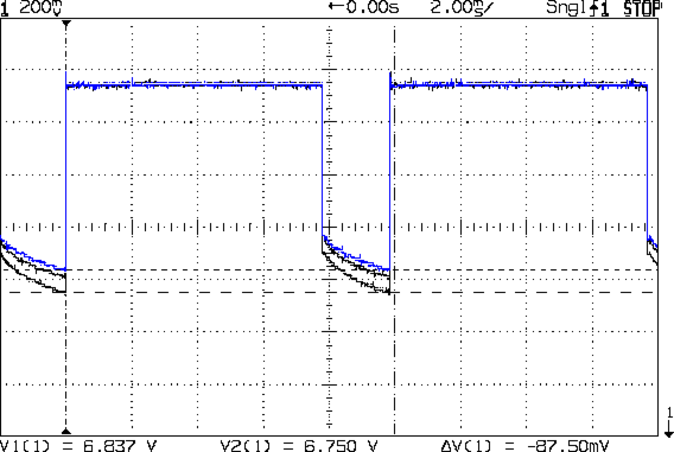
Maybe Eks has forgotten that he loaned me a Tek AM503 Hall effect current probe, which is exactly the right instrument to measure LED currents without introducing any series resistance. In order from the top, we have the amber, red 4-6, red 1-3, and red 7-9, with a scale of 20 mA/div (scope at 10 mV/div):
LED Current – Tek Hall probe – Y R2 R1 R3
The currents increase by 10 to 20 mA during the pulse, which suggests that the 25 °C thermal change I estimated based on the forward voltage really happens. The power supply decreases pretty much as a 120 mV step and doesn’t vary all that much during the pulse, so I think the LEDs control the current.
Here’s the forward voltage drop screenshot again for comparison (without the amber LEDs):
Red LED – group Vf
Overall, they run close enough to 100 mA for my simple needs…
It’d be nice to get Slashdotted or Hackaday-ed for something techie, rather than bedbugs again …
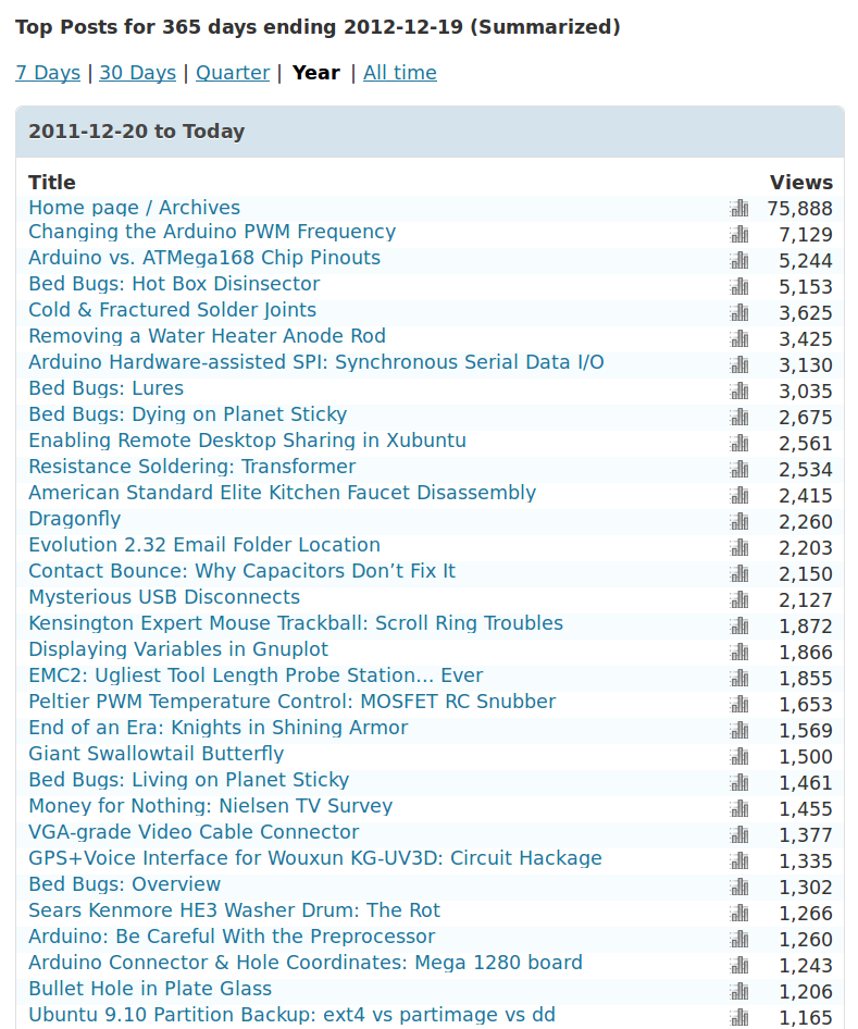
Surprisingly, most visitors arrive from image searches, rather than text searches:
2012 YTD Blog Referrer Stats
The largest non-search-engine referrer was Google Reader at 4000, followed by a Lifehacker traffic spike at 3000, and then everything else. As far as search engines go: Google and debris.
In round numbers, 650 visitors get 1000 total views per day; the overall views/visitor runs around 1.75, which I interpret to mean most folks find exactly what they want on the first page. As nearly as I can tell from the daily stats, 300 of you visit the main page and post-of-the-day, plus another 100 click in from the RSS feed. The numbers don’t add up, primarily because RSS feed clicks don’t seem to enter into their totals.
It’s definitely not a get-rich-quick scheme, that’s for sure…
It’s still fun and I really do use this blog as my notebook: some of those searches come from me. I appreciate you folks helping me out with useful comments and suggestion: thanks!
The collection of refrigerator words went off to college for the amusement and edification of our Larval Engineer’s compadres. These magnetic words emerged from nooks and crannies on and around the refrigerator over the next few months and form what must be the Ultimate Message from the Subconscious:
For reasons best left to the imagination, we needed some large signs for the front yard. I must look this up every time I do it, so here’s the process…
Create document in LibreOffice (or whatever), save as PDF
Convert PDF to EPS = Encapsulated Postscript
Apply poster to enlarge & paginate
Convert PS to PDF for ease of printing
Bash does the heavy lifting, after you install whatever packages your Linux distro may not have included:
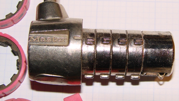
A Master Combination Lock emerged in locked condition from a box o’ stuff I handled during Mad Phil’s Great Cleanout. It’s not the highest security lock you’ll ever meet; about 15 minutes of fiddling produces the desired result:
Master Combo Padlock – opened
A bit of searching suggests it’s similar to the Master No. 1523D Combination Padlock, although this one came in pink. The doc describes how to change the combination:
Unlock (or crack) the lock
Pull off the spring-loaded endcap (I had to pry with a screwdriver)
Slide off the combination wheels
Reinstall in desired orientation
After removing the cap and wheels, it looks like this:
Master Combo Padlock – wheels off
Each wheel fits onto a rotating metal disk and engages three teeth, one of which has a notch. Align all four notches with the Master logo / index line and the lock opens:
Master Combo Padlock – dial alignment marks
Given just that picture, I think you can figure out how to get past one of these in a hurry. Right?