Ed Nisley's Blog: Shop notes, electronics, firmware, machinery, 3D printing, laser cuttery, and curiosities. Contents: 100% human thinking, 0% AI slop.
As nearly as I can tell, Epson designed a number of features into the R380 specifically to thwart CISS installation, including the awkward bridge across the middle of the printer that interferes with the flat tube feeding ink to the flying cartridges. I managed to route the previous CISS tubing around the bridge, but this time I figured enough was enough.
So I tucked a shop rag inside the printer, put a vacuum cleaner nozzle near the operation, and applied a fine-tooth pull saw to the bridge:
Epson R380 – bridge removed
That certainly simplified the rest of the installation…
Mary gave a gardening presentation at the local library, popping a 4 GB USB memory stick with the presentation into a library computer connected to the display projector. Back home, she deleted the presentations and was about to add more files, when she noticed something interesting:
drwx------  4 ed   ed    4096 Dec 31  1969 ./
drwxr-x---+ 3 root root  4096 Jan 31 19:21 ../
-r--r--r--  1 ed   ed   59288 Mar 21  2009 autorun.inf
drwx------  3 ed   ed    4096 Jan 30 19:31 RECYCLER/
drwx------  4 ed   ed    4096 Jan 31 19:10 .Trash-1001/
Ubuntu 12.10 automagically mounts FAT filesystems with the current user as owner and group. The .Trash-1001 directory is the Linux trash heap, but where did all that other stuff come from? The autorun.inf definitely looks Window-y, doesn’t it?
Perforce, the library runs Windows, but that shouldn’t add files to a USB memory stick that just was plugged in and used for a read-only presentation, should it?
Huh. You know where this is going…
Let’s hand autorun.inf to VirusTotal for a second opinion. The first three results from their long list confirm my suspicion:
Antivirus
Result
Update
Agnitum
INF.Conficker.F
20130131
AhnLab-V3
Win32/Conficker.worm
20130131
AntiVir
Worm/Kido.IH.40
20130131
The executable file containing the actual payload is, of course, buried in a subdirectory that might look more innocent on a Windows box: /RECYCLER/S-5-3-42-2819952290-8240758988-879315005-3665/
It sports a randomized name to evade a really stupid malware detector: jwgkvsq.vmx
Here’s what VirusTotal reports from some heavy hitters in the AV field:
Kaspersky
Net-Worm.Win32.Kido.ih
20130131
Kingsoft
Worm.Kido.ih.(kcloud)
20130131
Malwarebytes
Worm.Conficker
20130131
McAfee
W32/Conficker.worm
20130201
McAfee-GW-Edition
W32/Conficker.worm
20130131
Microsoft
Worm:Win32/Conficker.B
20130131
The Wikipedia article gives the details. I suppose that PC got it from somebody else’s USB stick, but the library really should be running some defensive software; Conficker dates back to 2008, so it’s not new news these days.
That kind of Windows Genuine Advantage makes up for all the hassles of running Linux, right there. Mary reported the problem to the library; we’ll never know the rest of the story.
Parallel port breakout boards of this ilk run about $14, complete with cable, on eBay:
5 axis parallel port breakout board
The PCB has no part number and the inferred URL isn’t productive. The “driver CD” accompanying it has doc for every possible board the vendor might sell and, absent a part number, the file names aren’t helpful. An exhaustive search suggests it corresponds to the HY-JK02-M 5-axis interface board manual.doc file.
Despite any implication to the contrary, the board does not have optoisolators between the parallel port pins and the outside world. The stepper driver bricks should, but the input signals from limit switches and suchlike connect directly to the guts of your PC.
This overview (from the manual) shows the physical pin layout (clicky for more dots) and reveals the hidden silkscreen legend:
HY-JK02-M Breakout Board – overview
It looks like the board I got added a spindle relay driver transistor, plus a few resistors over by the manual control connector on the right.
Notice that the fourth terminal on each axis is GND, not the positive supply required for the optoisolators on the 2M415-oid driver bricks, which means you can’t just run a section of ribbon cable from the breakout board to the brick. You’ll need a separate +5 V (or whatever) power supply wire for each brick, with a common return to the system ground for this board. Those terminals are firmly bonded to the top and bottom ground planes on the board, so there’s no practical way to re-route them.
The small switch in the upper left, just to the right of the parallel port connector, selects +5 V power from the USB port (which has no data lines) or the power connector in the lower left. The LED near the switch won’t light up until you have both the parallel port cable and the USB cable plugged in.
The doc includes a timing diagram with no numeric values. I established that it can’t keep up with a 500 kHz pulse train and seems content at 100 kHz, but that’s conjecture. Setting the timing to match whatever the stepper driver bricks prefer will probably work. The diagram suggests the setup and hold times for direction changes are whatever you use for the minimum time between step pulses.
This shows the functional labels:
HY-JK02-M Breakout Board – function labels
The parallel port connector output pins, sorted by function:
Pin
9
1
2
14
16
3
7
8
6
5
4
17
Function
Spindle
motor
Enabled
X step
X dir
Y step
Y dir
Z step
Z dir
A step
A dir
B step
B dir
The parallel port connector input functions, sorted by pin:
X -Limit
Y- Limit
Z- Limit
A- Limit
Emerg Stop
10
11
12
13
15
The table uses Chinese for Pin 15: 急停.
It’s not clear whether the pins on the manual control connector are inputs or outputs, nor what the three separate Enabled lines do:
P1
P2
P3
P4
P5
P6
P7
P8
P9
P10
P11
P12
P13
P14
P15
B step
B dir
A dir
Z step
Y step
X step
X dir
Enabled
5V/VDD
5V/GND
A step
Z dir
Y dir
Enabled
Enabled
The three white connectors in the middle drive an LED readout board that’s probably most useful as a DRO for CNC-converted manual mills using the pendant for positioning.
The small white connectors duplicate the functions of the green screw terminals. They’re probably useful in a small machine that I’m not building.
This isn’t the board I intend to use in the final setup, because I need far more I/O pins, but it’ll serve for the short term.
Collected from various spots around the Web, including evanescent eBay listings, and reformatted to make sense, these specs describe the 2M415 stepper driver: a smaller sibling of the 2M542 family.
Blurb
+15 to 40VDC Supply Voltage
H-Bridge, 2 Phase Bi-polar Micro-stepping Drive
Suitable for 2-phase, 4, 6 and 8 leads step motors, with Nema size 16 to 23
Output current selectable from 0.21 ~ 1.5A peak
Compact credit card size package
Optically isolated single ended TTL inputs for Pulse, Direction and Enable signal inputs
Selectable resolutions up to 12800 steps
Over Voltage, Coil to Coil and Coil to Ground short circuit protection.
Electrical specs
Parameters
Min
Typ
Max
Unit
Output Current (Peak)
0.21
–
1.5
Amp
Supply voltage
15
36
40
VDC
Logic Input Current
7
10
16
mA
Pulse input frequency
0
–
200
KHz
Low Level Time
2.5
µsec
Mechanical specs
Cooling
Natural Cooling or Forced Convection
Space
Avoid dust, oil, frost and corrosive gases
Ambient Temp
0 °C – 50 °C
Humidity
40 – 80 %RH
Vibration
5.9 m/s² Max
Storage Temp.
-10 °C – 80 °C
Weight
Approx. 150 gram
Dimensions
2M415 Footprint
Wiring diagram
2M415 Wiring
Notice that the driver requires a positive voltage for the optoisolators.
Of course, the box from halfway around the planet contained HB-415M drivers. Should you go looking with the usual keywords, you’ll find that HB-number turns up mostly “House Bill number” citations from various state legislatures. Popping the top off the drive reveals www.sikesai.com, which eventually produces a description and PDF datasheet for the driver. It turns out to be an “Ultra Low Noise” driver, whatever that means, with reasonably standard specifications that correspond more-or-less to the 2M415 drivers I thought I was getting.
This wonderful texture lives at the top of Cochran Hill Road, where I spotted it on a recent walk. That tiny hole on the right trunk suggests more trouble than meets the human eye…
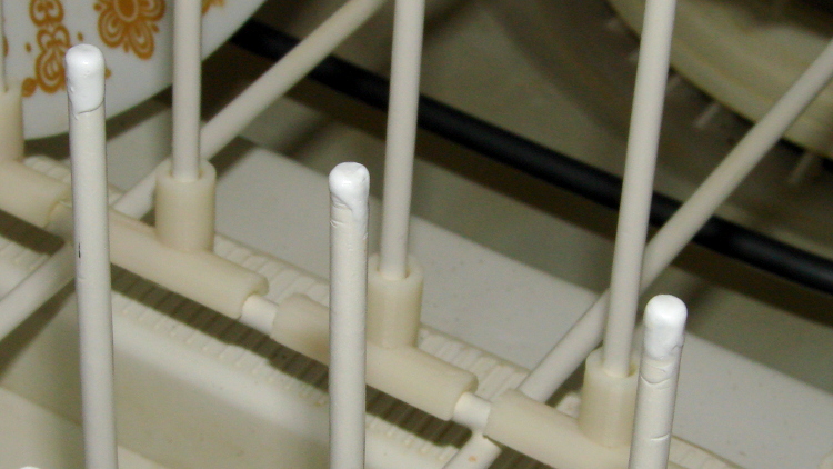
After that picture, the pins soaked for a while, got a rinse & blotting, then sat for a while to dry. I can’t say that’s in complete accordance with the directions, but it’s close to the spirit of the thing.
Meanwhile, the MEK / xylene / acetone I added to the bottle of stiffened ReRACK repair coating had softened it up pretty well. They recommend several coats at half-hour intervals, of which this was the first:
Dishwasher rack – first plastic layer
I probably should have chewed off the corrosion bulging the OEM coating, but, given the number of pins that needed chewing, that started looking like a major project. Let’s face it, I can always touch things up if the pins continue rotting out.
The next morning, the rack was back in service:
Dishwasher rack – recoated pins
One advantage of a big blob atop each pin: the printed rack protectors might not wriggle off quite so easily.
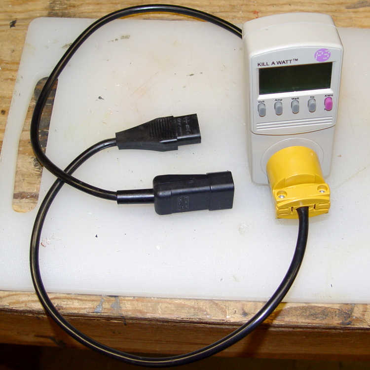
It makes measuring PC power consumption much easier!
I picked up some cheap AC plugs and sockets, cut a short IEC extender cable in half, and wired ’em up. If the IEC extender link breaks again, search amazon.com for something like “computer power cord extension” and rummage around.
US NEMA 5 plug / socket hint: the blade marked W is neutral. More expensive hardware will have dark brass = hot, light brass = neutral, but don’t bet your life on it.