Ed Nisley's Blog: Shop notes, electronics, firmware, machinery, 3D printing, laser cuttery, and curiosities. Contents: 100% human thinking, 0% AI slop.
I’ll be volunteering at the TCHFFRC this weekend, so if you happen to be near Hartford CT, drop in to see some high-pressure robot debugging.
You’ll find me behind the Robot Inspection Table, making sure everybody’s building robots that meet the same specifications. That’s a step up from a few years ago, when I got to dress the Granny Doll used in the RoboWaiter Contest…
Enthusiasm may get a product out, but engineering makes it work
Plywood and plastic do not produce a stable 3D printer
Measurements matter
8-bit microcontrollers belong in the dustbin of history
With that in mind, I’ve long thought that LinuxCNC (formerly EMC2) would provide a much better basis for the control software required for a 3D printer than the current crop of Arduino-based microcontrollers. LinuxCNC provides:
Hard real time motion control with proven performance
A robust, well-defined hardware interface layer
Ladder-logic machine control
Isolated userspace programming
Access to a complete Linux distro’s wealth of programs / utilities
Access to an x86 PC’s wealth of hardware gadgetry
Rather than (try to) force-fit new functions in an Arduino microcontroller, I decided it would be interesting to retrofit a DIY 3D printer with a LinuxCNC controller, improve the basic hardware control and sensing, instrument the extruder, then take measurements that might shed some light on DIY 3D printing’s current shortcomings.
Rebuild the extruder with temperature and force sensors
Start taking measurements!
My reasons for choosing the Makergear M2 as the basis for this project should be obvious:
All metal: no plywood, no acrylic (albeit a plastic filament drive)
Decent stepper motors (with one notable exception)
Reasonable hot end design
Good reputation
The first step of the overall plan included a meticulously documented M2 build that I figured would take a month or two, what with the usual snafus and gotchas that accompany building any complex mechanism. Quite by coincidence, a huge box arrived on my birthday (the Thing-O-Matic arrived on Christmas Eve, so perhaps this is a tradition), the day when I learned that Mad Phil had entered his final weeks of life.
As the Yiddish proverb puts it: If you wish to hear G*d laugh, tell him of your plans.
So I converted a box of parts into a functional M2 3D printer over the course of four intense days, alternating between our living room floor and a card table in Phil’s home office, showing him how things worked, getting his advice & suggestions, and swapping “Do you remember when?” stories. Another few days sufficed for software installation, configuration, and basic tuneup; I managed to show him some shiny plastic doodads just before he departed consensus reality; as nearly as I can tell, we both benefited from the distractions.
Which means I don’t have many pictures or much documentation of the in-process tweakage that produced a functional printer. The next week or so of posts should cover the key points in enough detail to be useful.
Not to spoil the plot or anything: a stock M2 works wonderfully well.
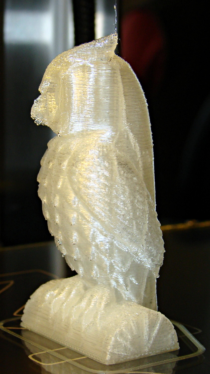
Owl – half size – left
For example, a half-scale cushwa owl printed in PLA at 165 °C with no bed cooling and these Slic3r parameters:
500 mm/s move
300 mm/s infill
200 mm/s solid infill
100 mm/s internal perimeter
50 mm/s bottom layer
30 mm/s external perimeter
1 mm retract @ 300 mm/s
The beak came out slightly droopy and each downward-pointing feather dangles a glittery drop. There’s room for improvement, but that’s pretty good a week after opening a box o’ parts…
I needed to replace all the ordinary spaces between numeric values and their units (as in 3.5 V) with non-breaking spaces. LibreOffice Writer implements regular expression searches, but their notion of marking and replacing references trips me up every time. This part of the Fine Manual describing how parenthesized targets work will come in handy again:
In the Search for box:
Defines the characters inside the parentheses as a reference. You can then refer to the first reference in the current expression with “\1”, to the second reference with “\2”, and so on.
For example, if your text contains the number 13487889 and you search using the regular expression (8)7\1\1, “8788” is found.
You can also use () to group terms, for example, “a(bc)?d” finds “ad” or “abcd”.
In the Replace with box:
Use $ (dollar) instead of \ (backslash) to replace references. Use $0 to replace the whole found string.
As nearly as I can tell, there is no escape sequence that denotes a non-breaking space, so I had to manually enter one using Shift+Ctrl+Spacebar, copy it, and paste it into the replacement text string.
The search-and-replace dialog looked like this:
LibreOffice RegEx Backreferences
Yes, you can search for strings inside parentheses, use parentheses to mark references, and then jam references in the replacement. This makes my head hurt every time: programming as an experimental science…
Running a random set of colored LEDs from the Basement Laboratory Parts Warehouse Wing through the LED Curve Tracer produced this pleasant plot:
The white LED doesn’t match up with either the blue or the UV LED. Perhaps the blue LED uses a completely different chemistry that shoves further to the right than seems proper? I suppose I should run a handful of white, blue, and UV LEDs through the thing just to see what’s going on…
The Bash / Gnuplot source code:
#!/bin/sh
numLEDs=8
#-- overhead
export GDFONTPATH="/usr/share/fonts/truetype/"
base="${1%.*}"
echo Base name: ${base}
ofile=${base}.png
echo Input file: $1
echo Output file: ${ofile}
#-- do it
gnuplot << EOF
#set term x11
set term png font "arialbd.ttf" 18 size 950,600
set output "${ofile}"
set title "${base}"
set key noautotitles
unset mouse
set bmargin 4
set grid xtics ytics
set xlabel "Forward Voltage - V"
set format x "%4.1f"
set xrange [0.5:4.5]
#set xtics 0,5
set mxtics 2
#set logscale y
#set ytics nomirror autofreq
set ylabel "Current - mA"
set format y "%3.0f"
set yrange [0:35]
set mytics 2
#set y2label "right side variable"
#set y2tics nomirror autofreq 2
#set format y2 "%3.0f"
#set y2range [0:200]
#set y2tics 32
#set rmargin 9
set datafile separator whitespace
set label 1 "IR" at 1.32,32 center
set label 2 "R"  at 1.79,32 center
set label 3 "O"  at 2.10,32 center
set label 4 "Y"  at 2.65,32 center
set label 5 "G"  at 2.42,32 center
set label 6 "B"  at 4.05,32 center
set label 7 "UV" at 3.90,32 center
set label 8 "W"  at 3.25,32 center
#set arrow from 2.100,32 to 2.125,31 lt 1 lw 2 lc 0
plot \
 "$1" index 0 using (\$5/1000):(\$2/1000) with linespoints pt 1 lw 2 lc rgb "red" ,\
 "$1" index 1 using (\$5/1000):(\$2/1000) with linespoints pt 1 lw 2 lc rgb "orange" ,\
 "$1" index 2 using (\$5/1000):(\$2/1000) with linespoints pt 1 lw 2 lc rgb "dark-yellow" ,\
 "$1" index 3 using (\$5/1000):(\$2/1000) with linespoints pt 1 lw 2 lc rgb "green" ,\
 "$1" index 4 using (\$5/1000):(\$2/1000) with linespoints pt 1 lw 2 lc rgb "blue" ,\
 "$1" index 5 using (\$5/1000):(\$2/1000) with linespoints pt 1 lw 2 lc rgb "purple" ,\
 "$1" index 6 using (\$5/1000):(\$2/1000) with linespoints pt 1 lw 2 lc rgb "magenta" ,\
 "$1" index 7 using (\$5/1000):(\$2/1000) with linespoints pt 1 lw 2 lc rgb "dark-gray"
EOF
Somehow, we wound up with a broom handle and a broom head, the former missing a threaded stub that was firmly lodged in the latter. A few minutes of Quality Shop Time sawed off the end of the handle and unscrewed the stub to produce this array of fragments:
Broken broom handle thread
It’s a cylindrical Thing tailor-made for (or, back in the day, by!) a lathe. My lathe has quick-change gears that can actually cut a 5 TPI thread, but that seems like a lot of work for such a crude fitting. Instead, an hour or so of desk work produced this:
Broom Handle Screw – solid model – overview
Some after-the-fact search-fu revealed that the thread found on brooms and paint rollers is a 3/4-5 Acme. Machinery’s Handbook has 13 pages of data for various Acme screw threads, making a distinction between General Purpose Acme threads and Stub Acme Threads: GP thread depth = 0.5 × pitch, Stub = 0.3 × pitch. For a 5 TPI thread = 0.2 inch pitch, that’s GP = 0.1 inch vs. Stub = 0.06 inch.
I measured a 5.0 mm pitch (which should be 5.08 mm = 0.2 inch exactly) and a crest-to-root depth of 1.4 mm = 0.055 inch, which makes them look like 3/4-5 Stub Acme threads. But, I didn’t know that at the time; a simple half-cylinder 2.5 mm wide and 1.25 mm tall was a pretty close match to what I saw on the broken plastic part.
Although OpenSCAD’s MCAD library has some screw forms, they’re either machine screws with V threads or ball screws with spheres. The former obviously weren’t appropriate and the latter produced far too many facets, so I conjured up a simpler shape: 32 slightly overlapping cylinders per turn, sunk halfway in the shaft at their midpoint, and tilted at the thread’s helix angle.
Broom Handle Screw – thread model closeup
The OpenSCAD source code has a commented-out section that removes a similar shape from the shaft between the raised thread, but that brought the rendering to its knees. Fortunately, it turned out to be unnecessary, but it’s there if you want it.
With the shaft diameter set to the “root diameter” of the thread and the other dimensions roughly matching the broken plastic bits, this emerged an hour later:
Broom handle screw plug – as built
The skirt thread was 0.25 to 0.30 mm thick, so the first-layer height tweak and packing density adjustments worked fine and all the dimensions came out perfectly. The cylindrical thread form doesn’t have much overhang and the threads came out fine; I think the correct straight-sided form would have more problems.
The hole down the middle accommodates a 1/4-20 bolt that applies enough clamping force to keep the shaft in compression, which ought to prevent it from breaking in normal use. I intended to use a hex bolt, but found a carriage bolt that was exactly the right length and had a head exactly the same diameter as the shaft, so I heated it with a propane torch and mushed its square shank into the top of the hexagonal bolt hole (the source code now includes a square recess):
Broom handle screw plug – in handle
The dimples on the side duplicate the method that secured the original plastic piece: four dents punched into the metal handle lock the plastic in place. It seems to work reasonably well, though, and is certainly less conspicuous than the screws I’d use.
Screwing it in place shows that it’s slightly too long (I trimmed the length in the source code):
Broom handle installed
It’s back in service, ready for use…
The OpenSCAD source code:
// Broom Handle Screw End Plug
// Ed Nisley KE4ZNU March 2013

// Extrusion parameters must match reality!
//  Print with +1 shells and 3 solid layers

ThreadThick = 0.25;
ThreadWidth = 2.0 * ThreadThick;

HoleWindage = 0.2;

function IntegerMultiple(Size,Unit) = Unit * ceil(Size / Unit);

Protrusion = 0.1;			// make holes end cleanly

//----------------------
// Dimensions

PI = 3.14159265358979;

PostOD = 22.3;              // post inside metal handle
PostLength = 25.0;

FlangeOD = 24.0;            // stop flange
FlangeLength = 3.0;

PitchDia = 15.5;            // thread center diameter
ScrewLength = 20.0;

ThreadFormOD = 2.5;         // diameter of thread form
ThreadPitch = 5.0;

BoltOD = 7.0;               // clears 1/4-20 bolt
BoltSquare = 6.5;          	// across flats
BoltHeadThick = 3.0;

RecessDia = 6.0;			// recesss to secure post in handle

OALength = PostLength + FlangeLength + ScrewLength; // excludes bolt head extension

$fn=8*4;

echo("Pitch dia: ",PitchDia);
echo("Root dia: ",PitchDia - ThreadFormOD);
echo("Crest dia: ",PitchDia + ThreadFormOD);

//----------------------
// Useful routines

module Cyl_Thread(pitch,length,pitchdia,cyl_radius,resolution=32) {

Cyl_Adjust = 1.25;                      // force overlap

    Turns = length/pitch;
    Slices = Turns*resolution;
    RotIncr = 1/resolution;
    PitchRad = pitchdia/2;
    ZIncr = length/Slices;
    helixangle = atan(pitch/(PI*pitchdia));
    cyl_len = Cyl_Adjust*(PI*pitchdia)/resolution;

    union() {
        for (i = [0:Slices-1]) {
            translate([PitchRad*cos(360*i/resolution),PitchRad*sin(360*i/resolution),i*ZIncr])
                rotate([90+helixangle,0,360*i/resolution])
                    cylinder(r=cyl_radius,h=cyl_len,center=true,$fn=12);
        }
    }
}

module PolyCyl(Dia,Height,ForceSides=0) {			// based on nophead's polyholes

  Sides = (ForceSides != 0) ? ForceSides : (ceil(Dia) + 2);

  FixDia = Dia / cos(180/Sides);

  cylinder(r=(FixDia + HoleWindage)/2,
           h=Height,
	   $fn=Sides);
}

module ShowPegGrid(Space = 10.0,Size = 1.0) {

  Range = floor(50 / Space);

	for (x=[-Range:Range])
	  for (y=[-Range:Range])
		translate([x*Space,y*Space,Size/2])
		  %cube(Size,center=true);

}

//-------------------
// Build it...

ShowPegGrid();

difference() {
    union() {
        cylinder(r=PostOD/2,h=PostLength);
        cylinder(r=PitchDia/2,h=OALength);
        translate([0,0,PostLength])
            cylinder(r=FlangeOD/2,h=FlangeLength);
        translate([0,0,(PostLength + FlangeLength)])
            Cyl_Thread(ThreadPitch,(ScrewLength - ThreadFormOD/2),PitchDia,ThreadFormOD/2);
    }

    translate([0,0,-Protrusion])
        PolyCyl(BoltOD,(OALength + 2*Protrusion),6);
    translate([0,0,(OALength - BoltHeadThick)])
        PolyCyl(BoltSquare,(BoltHeadThick + Protrusion),4);

//    translate([0,0,(PostLength + FlangeLength + ThreadFormOD)])
//        Cyl_Thread(ThreadPitch,(ScrewLength - ThreadFormOD/2),PitchDia,ThreadFormOD/2);

	for (i = [0:90:270]) {
		rotate(i)
			translate([PostOD/2,0,PostLength/2])
				sphere(r=RecessDia/2,$fn=8);
	}
}
My buddy Mad Phil’s obituary will read that he died from “complications of ALS“. In his case, he lived nearly three weeks after his swallowing reflex failed, whereupon he quietly and deliberately stopped eating and drinking. He slipped into intermittent unconsciousness last week, departed from consensus reality, and died of dehydration yesterday.
It’s not starvation, because you can survive for much longer than a month without food, but not even the correct name makes it prettier. The rule of thumb for death by dehydration gives you a week or two, tops, but early on I told him that he’d survive for a month on sheer cussedness. For reasons I’ll describe in a few days, I know from personal experience that he was still up and running after seven days. He slowed down a bit during the second week, but still held court from his bed 15 days after entering final approach.
We met, decades ago, at a locally important company whose name cannot be mentioned (but whose initials are IBM, if that helps), where he taught me a good deal of what I know about hardware construction and debugging. He was known as Mad Phil, not because he was crazy, but because when something important needed doing, he could get it done and you did not get between him and his goal.
Here’s how that worked, once upon a time:
Mad Phil and a bunch of techs are returning from a trip to a vendor in Massachusetts. Some of the guys plan to visit a favorite fishing hole on the way home, so they stop at a deli in a small town for provisions. Being young guys, they simply slam to a stop in a no-parking zone. A tech hops out of the back seat and runs into the deli.
Mad Phil sits in the passenger seat of the other car, a Chrysler Cordobarental pimpmobile, with a tech named Guido at the wheel; Guido looks exactly like you’d expect, dressed to impress right down to the open shirt and gold chain. Phil, being the responsible engineer in charge of the trip, is (uncharacteristically) wearing a suit. There being no parking, Guido makes loops around the traffic circle at the center of town. They spot a local police car near the deli, so Guido drives carefully.
After a few loops, the tech runs out of the deli with two large brown bags and waves at Guido, who pulls up between the police car and the deli. In quick succession, the policeman gets out of the patrol car, the tech tosses one bag into Guido’s lap, hops into the other car, and pulls out with unseemly haste.
The policeman studies Guido, Phil, the bag, and the Cordoba. Phil powers down his window, smiles, and asks “May we be of assistance, officer?” The policeman looks at both of them again, meets Phil’s gaze, and says “There’s no point, you’d be out of jail in fifteen minutes.” Phil replies “Thank you, officer, we appreciate your cooperation” and nods at Guido, who gently backs the car out, and they drive off in a stately manner.
He was obviously that guy you did not mess with.
Over the course of the last two years, after being diagnosed with ALS, he quietly and efficiently got his affairs in order, selling and donating his extensive collection of tools, equipment, and parts: putting his stuff where it would do the most good. He gave many tools to a local group that builds and repairs houses, helped stock the local hackerspace, gave me a wide assortment of doodads (some of which you’ve seen here), and was far more generous than anyone really should be.