Ed Nisley's Blog: Shop notes, electronics, firmware, machinery, 3D printing, laser cuttery, and curiosities. Contents: 100% human thinking, 0% AI slop.
Having recently kibitzed on a project using de-icing cables (with some success) to soften PVC pipe for bending, herewith the useful numbers.
Data printed on the original cable:
100 ft length
120 VAC
800 W
Derived values:
6.7 A = 800 W / 120 V
8 W/ft = 800 W / 100 ft
1.2 V/ft = 120 V / 100 ft
18 Ω = (120 V)2 / 800 W
180 mΩ/ft = 18 Ω / 100 ft
The starting point was a 62 ft length of the cable, as I’d long ago converted the end into a heated bed for starting plants early in the spring. That presented a resistance of 11 Ω, drew a current of 11 A, and dissipated 1.3 kW at 21 W/ft. A kilowatt-class dimmer handled the load, but adjoining sections of the cable got hot enough to melt the insulation and terminate the experiment.
A shorter length of cable might be suitable for a cheap laptop brick power supply. To keep the dissipation under, say, 10 W/ft, we have:
7.5 A = sqrt( 10 W/ft / 180 mΩ/ft )
1.3 V/ft = 7.5 A * 180 mΩ/ft
The Dell D220P-01 brick on the M2 provides 12 V at 18 A (!) and costs under $20 on eBay:
9 ft = 12 V / 1.3 V/ft
90 W = 12 V * 7.5 A
1.6 Ω = 9 ft * 180 mΩ/ft
You could run two 9 ft lengths cables in parallel from the same hulking brick. Whether that’s enough to soften a length of PVC pipe from the inside, without having the insulation get all melty, that’s another question…
I’m planning to put all the stepper driver bricks, solid state relays, power suppliers, miscellaneous doodads, and suchlike that will interface LinuxCNC with the M2 printer into a repurposed Dell desktop PC case.
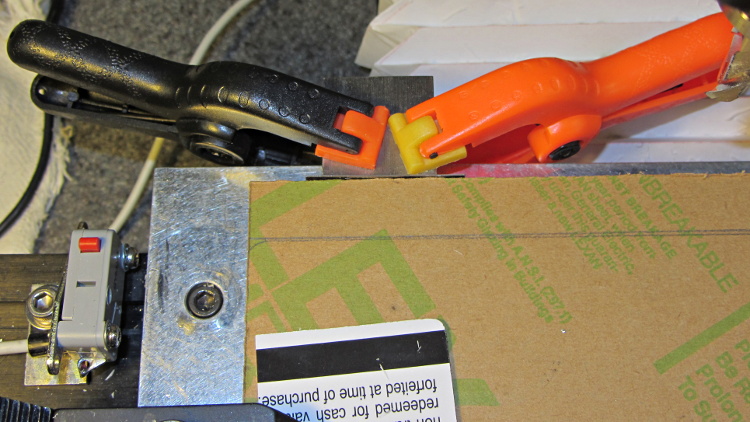
The front of the case had some tabs sticking out that anchored / aligned / captured various bits of hardware; grabbing them with a Vise-Grip, wiggling until the steel failed, and then filing the raw edge solved that problem:
Dell PC case – removing small tabs
The PC had room for a diskette drive, with a lip protruding below the opening:
Dell PC case – diskette drive slot tab
A welding pliers wiggled nearly the entire tab at once:
PC case – removing diskette drive tab
The bulky Dell front panel had four locating pins that mated with four round holes, one of which appears in the first picture. I wanted a somewhat less butt-ugly front than the bare metal grill, but still with some air flow into the case, so I found some 1/4 inch diameter standoffs tapped 4-40 that fit snugly in the holes and cut them to length:
Dell PC case – trimming panel mounts
Another defunct Dell case contributed a side panel with roughly the right color. Four match-drilled clearance holes later:
Dell PC case – vent panel
Just for effect, I squared up a slab of nice smoke-brown polycarb to cover the upper opening and perhaps hold das Blinkenlights. The slab was, as almost always happens, slightly too large for the Sherline, so I had to reclamp it to clean up all the sides. It came out about half a millimeter out of square and, being that type of guy, I clamped a block to the back of the table with a suitable spacer against the wide side, removed the spacer, loosened the step clamp on that end, rotated the slab against the block, made another pass, and it came out perfectly square:
Dell PC case – squaring polycarb panel
Four match-drilled holes and some epoxy later:
Dell PC case – polycarb panel mounts
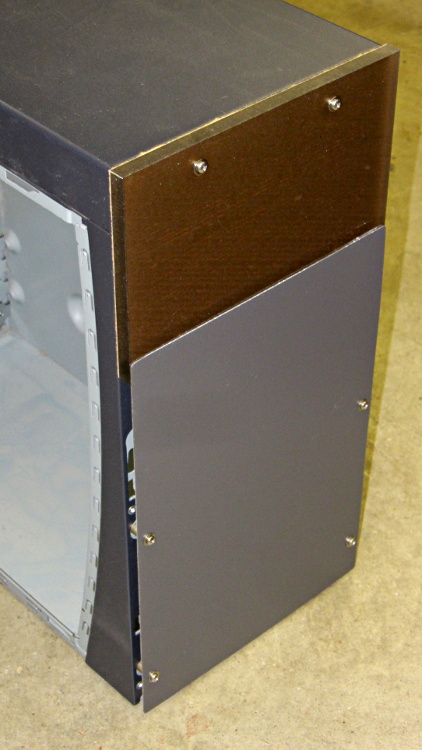
I’ll probably put the main AC switch on that top panel, but it looks pretty good even with the protective paper on the back:
Dell PC case – front panels
I must mill a recess under the vent panel and counterbore the screw heads so everything fits flush and lines up neatly.
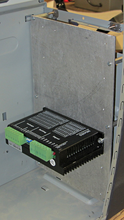
Another chunk of aluminum will hold the stepper driver bricks along the front of the case:
Dell PC case – stepper drive panel
I laid out the holes with a square, eyeballed the spacing on a machinist’s scale, manually punched / drilled / tapped the holes, and it’s all good. The standoffs provide a bit of airflow around the edges; I don’t expect the drivers to get more than slightly warm, because they’re running near the bottom of their current rating. Incidentally, that sheet is a different and much nicer alloy than the pure aluminum I jeweled for the main base plate and will probably not use.
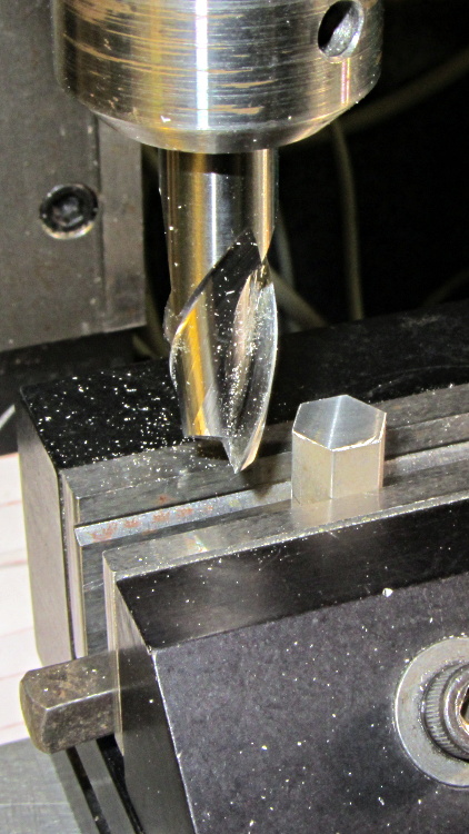
The 24 VDC power supply will mount on the top of the case, up where the Dell PC supply used to reside. The supply has M4 tapped holes and, of course, I don’t have any such standoffs, but I did find some hex standoffs with 6-32 tapped holes on both ends. Bandsaw ’em in half and clean up the raw end to the proper length:
Dell PC case – power supply standoffs – trimming
Center drill in the lathe / drill / tap an M4 thread in each one, saw off some M4 screws, slather with red Loctite, insert studs into standoffs, and that should hold the power supply in place with 6-32 screws through the case top:
Dell PC case – power supply standoffs
More Quality Shop Time lies ahead, but it’s coming together…
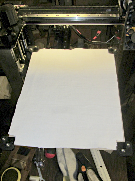
Although I don’t have any data to support the idea, it seems that there’s far too much heat loss from the bottom of the HBP. Admittedly, air is a great insulator, so most of the energy should go into the aluminum plate, but having air blow over the bottom can’t be a Good Thing. There’s a very thin space between the bottom of the silicone heater element and the black aluminum spider supporting the corners, so I added a thin cardboard sheet:
HBP insulation – cardboard base
The curiously shaped cutout clears the heater power wires, the thermistor in its lug, and the thermistor wires.
Atop that goes a pair of very thin cotton cloth sheets (again, not much to focus on, so it’s a bit blurry):
HBP insulation – cotton sheet
And then the plate fits atop the corner support pads as usual. I suppose the heater duty cycle should be lower at any given temperature, but I don’t have any records to compare against.
This message may be useful, in the sense that it reports something about the internal state of the cash register:
Walmart cash register – buffer full message
But the fact that it appears on the customer-facing display means that the cashier won’t see it and can’t do anything about it. I’m not sure if the floor personnel know anything about buffers, either.
The cashier-facing display says: “Welcome to Walmart!”
I have a deep and abiding cynicism about the wisdom of building Special Facilities for bicycles and pedestrians. We very much enjoy biking along the Dutchess County Rail Trail, but I fear the County’s initial enthusiasm and funding will quickly wear off, leaving us with another poorly maintained facility.
For example, the section of trail just south of Morgan Lake (a.k.a., Phase II) opened in July 2009, a mere four years ago. This view shows the North Grand Avenue at-grade crossing:
DCRT N Grand – overview
Shortly after the opening, the ADA-mandated vision-impaired tactile pavement strips at that crossing began to deteriorate and, by now, they’re just rubble-filled depressions across the trail on either side of the road.
The south strip:
DCRT N Grand – South ADA Strip
The north strip:
DCRT N Grand – north ADA strip
Evidently, the Official Personnel traversing the DCRT lack the responsibility / authority / initiative to apply a broom and sweep the pebbles out of the path, much less schedule a repair crew. I suppose I should haul a shovel along on one of our trips and privatize the upkeep; it’s been two years, so further waiting will be pointless.
It’s not as though there’s no Official Traffic, as witnessed by this well-worn informal entrance at the south end of that trail segment:
DCRT Overocker – vehicle tracks
There’s an Official Gate just to the left of the trail at that crossing, but, judging from the weeds, it’s evidently easier to stay in the car or truck than get out and unlock the barrier:
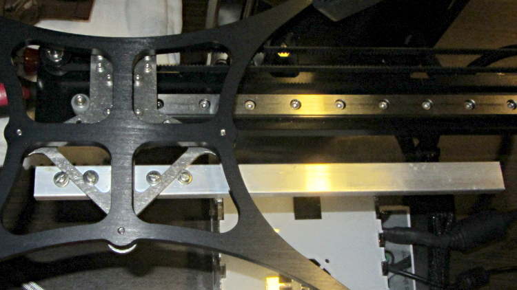
This overview shows the aluminum strut sticking out to the rear (Y+) end of the platform support spider:
HBP connector support strut – overview
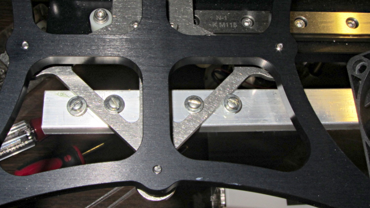
A closeup shows a quartet of 4-40 holes drilled and tapped along the strut’s midline:
HBP connector support strut – mounting detail
Admittedly, that’s a bit of a kludge, but I didn’t want to drill holes in that nice steel bracket… particularly since I’d have to dismantle the whole stage to get to it. The four screws wedge the strut firmly in position and have jam nuts on the bottom so they don’t loosen.
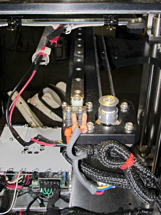
I extracted more wire from the braided sheath and moved the cable a bit further out at the cable tie holding it to the Y axis stage, then cable-tied the HBP connector to the strut.
With the stage all the way to the rear:
HBP connector support strut – at Y min
And to the front:
HBP connector support strut – at Y max
The wires may break, but now the HBP connector and heating pad joints should survive!
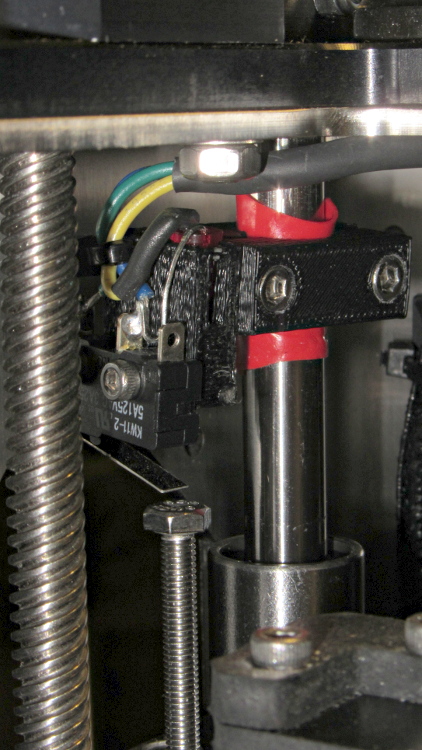
The printed bracket for the M2’s Z axis home switch doesn’t get a good grip on the oiled steel rod, so it can slide around just a little bit when nudged. That doesn’t happen often, but when it does, all your careful alignment Goes Away.
A single wrap of silicone tape solves that problem:
Z min switch on silicone tape
While I was in there, I replaced the socket-head cap screw I’d been using with a longer hex bolt and swapped the nylock nut for a plain nut that’s easier to adjust. I should file the raised markings off the top of the bolt head so it presents a smooth surface to the switch.