The Smell of Molten Projects in the Morning

Ed Nisley's Blog: Shop notes, electronics, firmware, machinery, 3D printing, laser cuttery, and curiosities. Contents: 100% human thinking, 0% AI slop.

Author: Ed

  • Mesa 5i25 + 7i76: HAL Pins

    Some notes on setting up the Mesa 5i25 FPGA card (the manual) with the 7i76 daughter card (the manual) inside a new-to-me off-lease Dell Optiplex 760

    First up: note that Mesa uses a capital I (“eye”) in the part numbers, a decision which they’ve surely had plenty of time to regret, as many common fonts exhibit nearly identical capital-I and digit-1 characters.

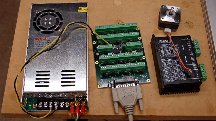
    The 7i76 connects to the 5i25 in the PC through a Mesa-supplied IEEE-1284 printer cable. I cobbled up a 24 VDC power supply (which I’ll eventually be using for the M2 motors) to provide “field power” and let the firmware identify the daughtercard:

    24 VDC power supply - Mesa 7i76 - stepper driver
    24 VDC power supply – Mesa 7i76 – stepper driver

    The default jumper positions on both cards work fine.

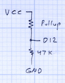
    The unconnected stepper driver brick and motor will serve as a simple demonstration after I’ve built the Eagle parts to represent the 5i25’s components. However, the first demo of any new hardware must be a blinking LED.

    To see whether the cards work and are detected, load the hostmot2 drivers in halrun and dump all the information:

    halrun
    halcmd: loadrt hostmot2
    halcmd: loadrt hm2_pci
    halcmd: show all
    Loaded HAL Components:
    ID      Type  Name                                      PID   State
         5  RT    hm2_pci                                         ready
         3  User  halcmd5010                                 5010 ready
         4  RT    hostmot2                                        ready
    
    Component Pins:
    Owner   Type  Dir         Value  Name
         5  bit   OUT         FALSE  hm2_5i25.0.7i76.0.0.input-00
         5  bit   OUT         FALSE  hm2_5i25.0.7i76.0.0.input-00-not
         5  bit   OUT         FALSE  hm2_5i25.0.7i76.0.0.input-01
    ... snippage ...
         5  bit   OUT         FALSE  hm2_5i25.0.7i76.0.0.input-30
         5  bit   OUT         FALSE  hm2_5i25.0.7i76.0.0.input-30-not
         5  bit   OUT         FALSE  hm2_5i25.0.7i76.0.0.input-31
         5  bit   OUT         FALSE  hm2_5i25.0.7i76.0.0.input-31-not
         5  bit   IN          FALSE  hm2_5i25.0.7i76.0.0.output-00
         5  bit   IN          FALSE  hm2_5i25.0.7i76.0.0.output-01
    ... snippage ...
         5  bit   IN          FALSE  hm2_5i25.0.7i76.0.0.output-15
         5  bit   IN          FALSE  hm2_5i25.0.7i76.0.0.spindir
         5  bit   IN          FALSE  hm2_5i25.0.7i76.0.0.spinena
         5  float IN              0  hm2_5i25.0.7i76.0.0.spinout
         5  s32   OUT             0  hm2_5i25.0.encoder.00.count
         5  s32   OUT             0  hm2_5i25.0.encoder.00.count-latched
         5  bit   I/O         FALSE  hm2_5i25.0.encoder.00.index-enable
         5  bit   IN          FALSE  hm2_5i25.0.encoder.00.latch-enable
         5  bit   IN          FALSE  hm2_5i25.0.encoder.00.latch-polarity
         5  float OUT             0  hm2_5i25.0.encoder.00.position
         5  float OUT             0  hm2_5i25.0.encoder.00.position-latched
         5  s32   OUT             0  hm2_5i25.0.encoder.00.rawcounts
         5  s32   OUT             0  hm2_5i25.0.encoder.00.rawlatch
         5  bit   IN          FALSE  hm2_5i25.0.encoder.00.reset
         5  float OUT             0  hm2_5i25.0.encoder.00.velocity
         5  s32   OUT             0  hm2_5i25.0.encoder.01.count
    ... snippage ...
         5  float OUT             0  hm2_5i25.0.encoder.01.velocity
         5  bit   OUT         FALSE  hm2_5i25.0.gpio.000.in
         5  bit   OUT          TRUE  hm2_5i25.0.gpio.000.in_not
         5  bit   OUT         FALSE  hm2_5i25.0.gpio.001.in
    ... snippage ...
         5  bit   OUT          TRUE  hm2_5i25.0.gpio.032.in
         5  bit   OUT         FALSE  hm2_5i25.0.gpio.032.in_not
         5  bit   OUT          TRUE  hm2_5i25.0.gpio.033.in
         5  bit   OUT         FALSE  hm2_5i25.0.gpio.033.in_not
         5  bit   IN          FALSE  hm2_5i25.0.led.CR01
         5  bit   IN          FALSE  hm2_5i25.0.led.CR02
         5  u32   IN     0x00000000  hm2_5i25.0.sserial.channel
         5  u32   IN     0x00000000  hm2_5i25.0.sserial.parameter
         5  u32   IN     0x00000000  hm2_5i25.0.sserial.port
         5  u32   OUT    0x00000000  hm2_5i25.0.sserial.port-0.fault-count
         5  u32   OUT    0x00000000  hm2_5i25.0.sserial.port-0.port_state
         5  bit   IN           TRUE  hm2_5i25.0.sserial.port-0.run
         5  bit   IN          FALSE  hm2_5i25.0.sserial.read
         5  u32   OUT    0x00000000  hm2_5i25.0.sserial.state
         5  u32   IN     0x00000000  hm2_5i25.0.sserial.value
         5  bit   IN          FALSE  hm2_5i25.0.sserial.write
         5  bit   IN          FALSE  hm2_5i25.0.stepgen.00.control-type
         5  s32   OUT             0  hm2_5i25.0.stepgen.00.counts
         5  float OUT             0  hm2_5i25.0.stepgen.00.dbg_err_at_match
         5  float OUT             0  hm2_5i25.0.stepgen.00.dbg_ff_vel
         5  float OUT             0  hm2_5i25.0.stepgen.00.dbg_pos_minus_prev_
         5  float OUT             0  hm2_5i25.0.stepgen.00.dbg_s_to_match
         5  s32   OUT             0  hm2_5i25.0.stepgen.00.dbg_step_rate
         5  float OUT             0  hm2_5i25.0.stepgen.00.dbg_vel_error
         5  bit   IN          FALSE  hm2_5i25.0.stepgen.00.enable
         5  float IN              0  hm2_5i25.0.stepgen.00.position-cmd
         5  float OUT             0  hm2_5i25.0.stepgen.00.position-fb
         5  float IN              0  hm2_5i25.0.stepgen.00.velocity-cmd
         5  float OUT             0  hm2_5i25.0.stepgen.00.velocity-fb
         5  bit   IN          FALSE  hm2_5i25.0.stepgen.01.control-type
    ... snippage ...
         5  float OUT             0  hm2_5i25.0.stepgen.09.velocity-fb
         5  bit   I/O         FALSE  hm2_5i25.0.watchdog.has_bit
    
    ... snippage ...
    
    Parameters:
    Owner   Type  Dir         Value  Name
         5  bit   RW          FALSE  hm2_5i25.0.7i76.0.0.output-00-invert
         5  bit   RW          FALSE  hm2_5i25.0.7i76.0.0.output-01-invert
    ... snippage ...
         5  bit   RW          FALSE  hm2_5i25.0.7i76.0.0.output-15-invert
         5  u32   RO     0x100000A5  hm2_5i25.0.7i76.0.0.serial-number
         5  bit   RW          FALSE  hm2_5i25.0.7i76.0.0.spindir-invert
         5  bit   RW          FALSE  hm2_5i25.0.7i76.0.0.spinena-invert
         5  float RW            100  hm2_5i25.0.7i76.0.0.spinout-maxlim
         5  float RW              0  hm2_5i25.0.7i76.0.0.spinout-minlim
         5  float RW            100  hm2_5i25.0.7i76.0.0.spinout-scalemax
         5  u32   RO     0x00000000  hm2_5i25.0.7i76.0.0.status
         5  bit   RW          FALSE  hm2_5i25.0.encoder.00.counter-mode
         5  bit   RW           TRUE  hm2_5i25.0.encoder.00.filter
         5  bit   RW          FALSE  hm2_5i25.0.encoder.00.index-invert
         5  bit   RW          FALSE  hm2_5i25.0.encoder.00.index-mask
         5  bit   RW          FALSE  hm2_5i25.0.encoder.00.index-mask-invert
         5  float RW              1  hm2_5i25.0.encoder.00.scale
         5  float RW            0.5  hm2_5i25.0.encoder.00.vel-timeout
         5  bit   RW          FALSE  hm2_5i25.0.encoder.01.counter-mode
    ... snippage ...
         5  float RW            0.5  hm2_5i25.0.encoder.01.vel-timeout
         5  bit   RW          FALSE  hm2_5i25.0.gpio.000.invert_output
         5  bit   RW          FALSE  hm2_5i25.0.gpio.000.is_opendrain
         5  bit   RW          FALSE  hm2_5i25.0.gpio.001.invert_output
    ... snippage ...
         5  bit   RW          FALSE  hm2_5i25.0.gpio.030.invert_output
         5  bit   RW          FALSE  hm2_5i25.0.gpio.030.is_opendrain
         5  bit   RW          FALSE  hm2_5i25.0.gpio.030.is_output
         5  bit   RW          FALSE  hm2_5i25.0.io_error
         5  s32   RO              0  hm2_5i25.0.pet_watchdog.time
         5  s32   RW              0  hm2_5i25.0.pet_watchdog.tmax
         5  s32   RO              0  hm2_5i25.0.read.time
         5  s32   RW              0  hm2_5i25.0.read.tmax
         5  s32   RO              0  hm2_5i25.0.read_gpio.time
         5  s32   RW              0  hm2_5i25.0.read_gpio.tmax
         5  u32   RW     0x00000001  hm2_5i25.0.sserial.port-0.fault-dec
         5  u32   RW     0x0000000A  hm2_5i25.0.sserial.port-0.fault-inc
         5  u32   RW     0x000000C8  hm2_5i25.0.sserial.port-0.fault-lim
         5  u32   RW     0x00077FE2  hm2_5i25.0.stepgen.00.dirhold
         5  u32   RW     0x00077FE2  hm2_5i25.0.stepgen.00.dirsetup
         5  float RW              1  hm2_5i25.0.stepgen.00.maxaccel
         5  float RW              0  hm2_5i25.0.stepgen.00.maxvel
         5  float RW              1  hm2_5i25.0.stepgen.00.position-scale
         5  u32   RW     0x00000000  hm2_5i25.0.stepgen.00.step_type
         5  u32   RW     0x00077FE2  hm2_5i25.0.stepgen.00.steplen
         5  u32   RW     0x00077FE2  hm2_5i25.0.stepgen.00.stepspace
         5  u32   RW     0x00077FE2  hm2_5i25.0.stepgen.01.dirhold
    ... snippage ...
         5  u32   RW     0x00077FE2  hm2_5i25.0.stepgen.09.stepspace
         5  u32   RW     0x004C4B40  hm2_5i25.0.watchdog.timeout_ns
         5  s32   RO              0  hm2_5i25.0.write.time
         5  s32   RW              0  hm2_5i25.0.write.tmax
         5  s32   RO              0  hm2_5i25.0.write_gpio.time
         5  s32   RW              0  hm2_5i25.0.write_gpio.tmax
    
    Parameter Aliases:
     Alias                                      Original Name
    
    Exported Functions:
    Owner   CodeAddr  Arg       FP   Users  Name
     00005  fc3d2582  f1b17000  NO       0   hm2_5i25.0.pet_watchdog
     00005  fc3c49dc  f1b17000  YES      0   hm2_5i25.0.read
     00005  fc3c4906  f1b17000  YES      0   hm2_5i25.0.read_gpio
     00005  fc3c4936  f1b17000  YES      0   hm2_5i25.0.write
     00005  fc3c48d6  f1b17000  YES      0   hm2_5i25.0.write_gpio
    
    ... snippage ...
    

    Extract the 5i25 pin assignments from the kernel log file:
    dmesg | grep hm2

    Which produces this:

    [ed@lcnc-m2 LinuxCNC for M2]$ dmesg | grep hm2
    [ 7299.887856] hm2: loading Mesa HostMot2 driver version 0.15
    [ 7407.514601] hm2_pci: loading Mesa AnyIO HostMot2 driver version 0.7
    [ 7407.514631] hm2_pci 0000:04:02.0: PCI INT A -> GSI 18 (level, low) -> IRQ 18
    [ 7407.514634] hm2_pci: discovered 5i25 at 0000:04:02.0
    [ 7407.514656] hm2: no firmware specified in config modparam!  the board had better have firmware configured already, or this won't work
    [ 7407.515018] hm2/hm2_5i25.0: Smart Serial Firmware Version 38
    [ 7407.632326] hm2/hm2_5i25.0: 34 I/O Pins used:
    [ 7407.632329] hm2/hm2_5i25.0:     IO Pin 000 (P3-01): StepGen #0, pin Direction (Output)
    [ 7407.632331] hm2/hm2_5i25.0:     IO Pin 001 (P3-14): StepGen #0, pin Step (Output)
    [ 7407.632334] hm2/hm2_5i25.0:     IO Pin 002 (P3-02): StepGen #1, pin Direction (Output)
    [ 7407.632336] hm2/hm2_5i25.0:     IO Pin 003 (P3-15): StepGen #1, pin Step (Output)
    [ 7407.632338] hm2/hm2_5i25.0:     IO Pin 004 (P3-03): StepGen #2, pin Direction (Output)
    [ 7407.632340] hm2/hm2_5i25.0:     IO Pin 005 (P3-16): StepGen #2, pin Step (Output)
    [ 7407.632343] hm2/hm2_5i25.0:     IO Pin 006 (P3-04): StepGen #3, pin Direction (Output)
    [ 7407.632345] hm2/hm2_5i25.0:     IO Pin 007 (P3-17): StepGen #3, pin Step (Output)
    [ 7407.632347] hm2/hm2_5i25.0:     IO Pin 008 (P3-05): StepGen #4, pin Direction (Output)
    [ 7407.632349] hm2/hm2_5i25.0:     IO Pin 009 (P3-06): StepGen #4, pin Step (Output)
    [ 7407.632352] hm2/hm2_5i25.0:     IO Pin 010 (P3-07): Smart Serial Interface #0, pin TxData0 (Output)
    [ 7407.632354] hm2/hm2_5i25.0:     IO Pin 011 (P3-08): Smart Serial Interface #0, pin RxData0 (Input)
    [ 7407.632356] hm2/hm2_5i25.0:     IO Pin 012 (P3-09): IOPort
    [ 7407.632358] hm2/hm2_5i25.0:     IO Pin 013 (P3-10): IOPort
    [ 7407.632360] hm2/hm2_5i25.0:     IO Pin 014 (P3-11): Encoder #0, pin Index (Input)
    [ 7407.632362] hm2/hm2_5i25.0:     IO Pin 015 (P3-12): Encoder #0, pin B (Input)
    [ 7407.632364] hm2/hm2_5i25.0:     IO Pin 016 (P3-13): Encoder #0, pin A (Input)
    [ 7407.632367] hm2/hm2_5i25.0:     IO Pin 017 (P2-01): StepGen #5, pin Direction (Output)
    [ 7407.632369] hm2/hm2_5i25.0:     IO Pin 018 (P2-14): StepGen #5, pin Step (Output)
    [ 7407.632371] hm2/hm2_5i25.0:     IO Pin 019 (P2-02): StepGen #6, pin Direction (Output)
    [ 7407.632373] hm2/hm2_5i25.0:     IO Pin 020 (P2-15): StepGen #6, pin Step (Output)
    [ 7407.632376] hm2/hm2_5i25.0:     IO Pin 021 (P2-03): StepGen #7, pin Direction (Output)
    [ 7407.632378] hm2/hm2_5i25.0:     IO Pin 022 (P2-16): StepGen #7, pin Step (Output)
    [ 7407.632380] hm2/hm2_5i25.0:     IO Pin 023 (P2-04): StepGen #8, pin Direction (Output)
    [ 7407.632382] hm2/hm2_5i25.0:     IO Pin 024 (P2-17): StepGen #8, pin Step (Output)
    [ 7407.632385] hm2/hm2_5i25.0:     IO Pin 025 (P2-05): StepGen #9, pin Direction (Output)
    [ 7407.632387] hm2/hm2_5i25.0:     IO Pin 026 (P2-06): StepGen #9, pin Step (Output)
    [ 7407.632389] hm2/hm2_5i25.0:     IO Pin 027 (P2-07): IOPort
    [ 7407.632391] hm2/hm2_5i25.0:     IO Pin 028 (P2-08): IOPort
    [ 7407.632392] hm2/hm2_5i25.0:     IO Pin 029 (P2-09): IOPort
    [ 7407.632394] hm2/hm2_5i25.0:     IO Pin 030 (P2-10): IOPort
    [ 7407.632396] hm2/hm2_5i25.0:     IO Pin 031 (P2-11): Encoder #1, pin Index (Input)
    [ 7407.632398] hm2/hm2_5i25.0:     IO Pin 032 (P2-12): Encoder #1, pin B (Input)
    [ 7407.632401] hm2/hm2_5i25.0:     IO Pin 033 (P2-13): Encoder #1, pin A (Input)
    [ 7407.632443] hm2/hm2_5i25.0: registered
    [ 7407.632445] hm2_5i25.0: initialized AnyIO board at 0000:04:02.0
    [ 7487.136417] hm2_5i25.0: dropping AnyIO board at 0000:04:02.0
    [ 7487.136422] hm2/hm2_5i25.0: unregistered
    [ 7487.136440] hm2_pci 0000:04:02.0: PCI INT A disabled
    [ 7487.136459] hm2_pci: driver unloaded
    [ 7487.138640] hm2: unloading
    

    I am, perhaps, easily confused, but it took me a while to realize those pin assignments apply to the 5i25 back panel and on-card connectors, not the 7i76 daughter card’s screw terminals. Yeah, it says 5i25 right there in the dump, but …

    The Fine 7i76 Manual gives the 7i76 pin connections, so they’re not even slightly hidden. [sigh]

    Next, to see if it actually works …

  • Monthly Image: Turtles on a Log

    These Eastern Painted Turtles have hauled themselves out for a contemplative basking session nearly every time I ride by the pond at the entrance to the Vassar Farm and Ecological Preserve:

    Turtles on a Log - Vassar Farm Pond
    Turtles on a Log – Vassar Farm Pond

    What do turtles think about while they’re basking?

    Those turtles are probably relatives, even if they’re in a different pond farther downstream along the Casperkill.

  • Arduino Survival Guide: Workbench Edition

    Pullup Voltage Divider
    Pullup Voltage Divider

    Herewith, the slides for the talk + lab session I’m doing today for Squidwrench:

    Arduino Survival Guide – Workbench Edition

    Unlike most Arduino courses, I assume you’re already OK with the programming, but are getting tired of replacing dead Arduinos and want to know how to keep them alive. The course description says it all:

    Learn how to help your Arduino survive its encounter with your project, then live long and prosper. Discover why feeding it the proper voltages, currents, and loads ensures maximum Arduino Love!

    Ed will describe some fundamental electronic concepts, guide you at the workbench while you make vital measurements, then show you how to calculate power dissipation, load current, and more. You’ll understand why Arduinos get hot, what kills output bits, and how you can finally stop buying replacements.

    Among other lab exercises, we’ll measure the value of the ATmega’s internal pullup resistors, which everybody assumes are 20 kΩ, but probably aren’t. Hint: you can apply Ohm’s Law twice to that simple circuit and come up with the right answer, but only if you’ve measured the actual VCC voltage on the board.

    The Mighty Thor will detail how to not prepare Fried Raspberry Pi.

    In the unlikely event you’re in Highland NY, stop by: you’re bound to learn something.

  • LinuxCNC: Optiplex 760 Setup

    I planned to use an old Dell Inspiron 531S AMD desktop for the LinuxCNC installation, but it turned out to have terrible interrupt latency, despite fiddling with all the available BIOS settings and video drivers. Mostly, it ran fine, but would occasionally burp up a millisecond-long latency spike for no apparent reason. So it’s now on the harvest / recycle heap.

    A new-to-me off-lease Dell Optiplex 760 Core 2 Duo in the SDT (Small Desktop Tower) configuration has similar latency numbers:

    Optiplex 760 latency - isolcpu 1
    Optiplex 760 latency – isolcpu 1

    What’s important here is that the latency remains rock-solid stable at those numbers. Contrary to my experience with the D520 and D525 Atoms, isolating one CPU for the real-time tasks didn’t make any noticeable difference, but it’s running that way because the overall performance isn’t a problem.

    Latency around 20 μs is near the upper limit for successful software step generation at any reasonable pace; the LinuxCNC description has more details. In round numbers, running the M2 at 500 mm/s needs a 40 kHz step rate in 1/16 microstep mode = a 25 μs period, which means 20 μs of jitter wouldn’t work well at all. Which is why I’m using Mesa FPGA card to get hardware step generation: it makes such problems Go Away.

    The Optiplex arrived with Windows Vista Business preinstalled; it dates back to mid-2009. I used System Rescue CD to shrink the Windows partition, added a few more, then installed LinuxCNC direct from the CD image (based on Ubuntu 10.04 LTS) and Xubuntu 13.04. The latter serves as a general-purpose installation for times when I don’t need LinuxCNC, because 10.04 is pretty much obsolete for anything other than real-time control.

    Digression 1: Yes, 10.04 LTS. TheRTAI project hasn’t released the patches that will slip the real-time kernel under the stock 3.x Linux kernel: LinuxCNC remains stuck at 10.04 LTS. Those changes have been coming Real Soon Now for quite a while; as with most Open Source projects, they could use more manpower and money. This isn’t a problem, as LinuxCNC is used for motion control, not a general-purpose operating system.

    The SDT case has room for two PCI cards and one PCI-E video card, so I installed the dual-head video card that couldn’t handle the U2711 monitor’s dual-DVI connection (although I’m using only DVI Output 1) and a Mesa 5i25. The middle “card” is actually a tiny PCB connected to a ribbon cable that brings out a second serial port (remember serial ports?) and what could be either or both of a PS2 keyboard or mouse connection (remember PS/2?).

    Optiplex 760 SDT - dual DVI - serial - 5i25
    Optiplex 760 SDT – dual DVI – serial – 5i25

    The back panel has a parallel printer port (which may come in handy for something) and a serial port, although you’re expected to have USB mice and keyboards these days. The front panel even has a floppy drive…

    Digression 2: LinuxCNC does not require a parallel printer port; this seems to be a common misconception among folks who don’t actually know how it works. The Mesa 5i25 FPGA card with a 7i76 step-direction daughter board provides high-resolution timing for five axes, rotary encoder inputs, a bunch of buffered digital I/O bits, a watchdog timer, plus various other useful odds and ends, all behind handy screw terminals.

    The Optiplex 760 has on-board VGA-class video that would also work fine, but the monitor I’m using has its VGA input connected to the box driving the Sherline mill and an unused DVI input. Having that dual-DVI monitor card lying around, I figured I could attach the same monitor to both systems and just poke the monitor’s input section button; I’ve found KVM switches unreliable in this application.

    The usual setup preps the system for public-key SSH on a nonstandard port, sets up the NFS mounts, and tweaks this-and-that: it’s running just fine.

    Digression 3: SSH kvetches when you swap server boxes at the same IP address, as well it should. If you’re foolish enough to have two separate Linux installs on the same box with the same IP, SSH reminds you every time you boot the other distro…

  • Automated Scan-and-Enhance: ImageMagick to the Rescue

    Mary’s folks enjoy the daily crossword, but they wanted a slightly larger edition… and, after a bit of procrastination, I conjured up an automated way to make it happen, so her father need not do this manually with The GIMP and Xsane.

    The scanner, an old HP Scanjet 3970, dropped off the Windows driver list after Vista, so it now runs only with Linux.

    Doing the scan is straightforward, as it’s the default scanner:

    scanimage --mode Gray --opt_emulategray=yes --resolution 300 -x 115 -y 210 --format=pnm & scan.pnm
    

    The X and Y coordinates set the scan dimensions in millimeters, which should be as small as possible consistent with scanning the whole crossword.

    The driver produces output image files in PNM format, which isn’t particularly common these days, or TIFFImageMagick knows what to do with both of them; I picked PNM.

    Unfortunately, for some unknown reason, the SANE driver produces a severely low-contrast image:

    HP3900 Grayscale Scan
    HP3900 Grayscale Scan

    ImageMagick can produce a histogram:

    convert scan.pnm histogram:hist.png
    

    Which shows the problem:

    HP3900 Grayscale Histogram
    HP3900 Grayscale Histogram

    That’s using the grayscale emulation mode: the driver does a Color scan and converts to Gray mode for the output image. It seems having the driver do the conversion produces better results than scanning directly in Color and then applying ImageMagick, but it’s not my scanner and I don’t have a lot of experience with it.

    Given the PNM image:

    • Blow out the contrast
    • Resize the scan to fill the page
    • Crisp up the edges a bit
    convert scan.pnm -level 45%,60% -resize 2400x3000 +repage -unsharp 0 trim.png
    

    Which looks like this:

    Crossword - contrasty resize
    Crossword – contrasty resize

    This being Linux, the best way to print something is with either Postscript or PDF. I used PDF, because then we can look at the results with Reader, a more familiar program than, say, Evince:

    convert -density 300 -size 2550x3300 canvas:white trim.png -gravity center -composite page.pdf
    

    Which centers the crossword on the page over a white background with enough margin to keep the printer happy:

    Crossword - full page
    Crossword – full page

    That PDF goes to the default printer queue, where it’s turned into Postscript and comes out exactly like it should:

    lp page.pdf
    

    I gimmicked the default printer instance to use only black ink by creating a separate CUPS printer with the appropriate defaults. Other programs pay no attention to that setting and the printer uses colored inks. There is no explanation I can find for any of this; Linux / CUPS printing is basically a black box operation.

    In theory, you could print the composited image file as a PNG or some such, but I cannot make it come out the right size in the right place.

    You could do all of that in one line, with one huge ImageMagick invocation kicking off the scan and firing the result to the printer, but leaving some intermediate results lying along the trail isn’t necessarily a Bad Thing. I should probably use random temporary file names, though, in the interest of not polluting the namespace.

    All this happened remotely, with me signed on through SSH: hooray for the command line. Had to use SCP a few times to fetch those intermediate files to puzzle over the results, too.

    The complete Bash script:

    #!/bin/bash
    scanimage --mode Gray --opt_emulategray=yes --resolution 300 -x 115 -y 210 --format=pnm > /tmp/scan.pnm
    convert /tmp/scan.pnm -level 45%,60% -resize 2400x3000 +repage -unsharp 0 /tmp/trim.png
    convert -density 300 -size 2550x3300 canvas:white /tmp/trim.png -gravity center -composite /tmp/page.pdf
    lp /tmp/page.pdf
    

    A slightly closer scan crop with left and top margins may also work, at the cost of more precise positioning on the scanner:

    #!/bin/bash
    scanimage --mode Gray --opt_emulategray=yes --resolution 300 -l 5 -t 6 -x 105 -y 190 --format=pnm > /tmp/scan.pnm
    
    
  • Portable AC Vent Plug

    This plug for a portable air conditioner’s window vent may be un-buildable with my current state of 3D printer-fu. The top view shows the recess for a disk of insulating foam:

    Portable AC Vent Plug - solid model - top
    Portable AC Vent Plug – solid model – top

    The side view shows the thread profile and the groove for the O-ring seal:

    Portable AC Vent Plug - solid model - side
    Portable AC Vent Plug – solid model – side

    The bottom view shows the hemispheric finger grip recess:

    Portable AC Vent Plug - solid model - bottom
    Portable AC Vent Plug – solid model – bottom

    Basically, that design requires extensive support material no matter how it’s laid out. I tried the obvious way without any support, but that huge flat surface popped off the glass:

    AC Vent Plug - flat build
    AC Vent Plug – flat build

    The thread and groove overhangs in that orientation would require support and then extensive cleanout. Slic3r doesn’t do a good job of supporting internal layers, so the bottom of the recesses tend to flop into the hexagonal infill. I’m not sure building internal support all the way up the inside of the threads would be a Good Thing, though.

    Rotating by 90 degrees and cutting it in half failed because the automagic support structure popped off the platform:

    AC Vent Plug - split build
    AC Vent Plug – split build

    Admittedly, that was before I started using hairspray (on the platform!), but both orientations require far too much support. In fact, the rotated version might weigh half a kilo…

    I’m also generating the thread elements incorrectly; the joints don’t meet smoothly at the junctions. I think tapering each element so the smaller end nests inside the larger end will work better. Perhaps using a scaled hexagonal element would be better / faster than the current extruded 2D shape?

    I think the correct way to proceed will be a 3D print of the finger grip and flange section, oriented so the hemisphere points upward, with the threaded section made from a length of PVC pipe with lathe-turned threads and O-ring groove, butted against the flange around the grip section.

    Problem: that’s an 8 mm pitch thread and my inch-size lathe doesn’t do metric:

    • Need: 8 mm = 0.315 in → 3.175 TPI
    • Closest: 3-1/4 TPI → 0.308 in = 7.82 mm
    • Worse: 3 TPI → 0.333 in = 8.47 mm

    The plug needs about three turns, which means the 3-1/4 TPI = 7.82 mm pitch thread would be off by 0.54 mm, roughly a third of the thread form’s crest. That might actually work, as the “thread” on the inside of the pipe this thing fits into is actually a thin ridge, rather than an actual thread shape, and the plug is supposed to jam against the flange anyway.

    Maybe a four-axis setup in the Sherline, with the rotary table holding the PVC pipe (or whatever) aligned with the X axis? It would just barely fit under the spindle with the end mill in a collet.

    The pipe rack doesn’t hold any suitable plastic pipe.

    The OpenSCAD source code:

    // Portable AC Vent Plug
    // Ed Nisley KE4ZNU - June 2013
    
    Layout = "Show";			// Show Build Grip Helix HelixUnit Ring Plug Stiffener
    //-------
    //- Extrusion parameters must match reality!
    //  Print with +0 shells and 3 solid layers
    
    ThreadThick = 0.25;
    ThreadWidth = 0.40;
    
    HoleWindage = 0.3;
    
    Protrusion = 0.1;			// make holes end cleanly
    
    function IntegerMultiple(Size,Unit) = Unit * ceil(Size / Unit);
    
    //-------
    // Plug Dimensions
    
    PlugLength = 53.0;
    PlugOD = 128.0;
    
    FlangeThick = 5.0;
    FlangeWidth = 4.0;
    FlangeOD = 2*FlangeWidth + PlugOD;
    
    HelixPitch = 8.0;
    HelixOffset = 29.0 - HelixPitch/2;		// add half turn to ensure snug fit against flange
    HelixLength = PlugLength - HelixOffset;
    HelixDepth = 3.0;
    HelixBase = 3.5;
    HelixTip = 1.8;
    
    ORingDia = 3.4;
    ORingDepth = 0.75 * ORingDia;
    ORingOffset = ORingDia/2;
    
    GripOD = 90.0;
    GripDepth = 20.0;
    GripBar = 15.0;
    
    AlignDia = 3.0;
    AlignDepth = 5.0;
    
    FoamOD = PlugOD - 4*HelixDepth;
    FoamDepth = PlugLength - GripDepth;
    
    NumSides = 12*4;
    $fn = NumSides;
    
    echo("Flange OD: ",FlangeOD);
    echo("Overall length:",(FlangeThick + PlugLength));
    
    module PolyCyl(Dia,Height,ForceSides=0) {			// based on nophead's polyholes
    
      Sides = (ForceSides != 0) ? ForceSides : (ceil(Dia) + 2);
    
      FixDia = Dia / cos(180/Sides);
    
      cylinder(r=(FixDia + HoleWindage)/2,h=Height,$fn=Sides);
    }
    
    module ShowPegGrid(Space = 10.0,Size = 1.0) {
    
      RangeX = floor(100 / Space);
      RangeY = floor(125 / Space);
    
    	for (x=[-RangeX:RangeX])
    	  for (y=[-RangeY:RangeY])
    		translate([x*Space,y*Space,Size/2])
    		  %cube(Size,center=true);
    
    }
    
    //-------
    // Recessed finger grip
    // Includes Protrusion below Z=0 for clean removal from plug
    
    module GripShape(Length,Width,Depth) {
    
    Radius = (pow(Depth,2) + pow(Length,2)/4) / (2*Depth);
    
    	difference(convexity=2) {
    		intersection() {
    			translate([0,0,(-Radius + Depth)])
    				sphere(r=Radius);
    			translate([0,0,(Depth/2 - Protrusion)])
    				cube([2*Radius,2*Radius,(Depth + Protrusion)],center=true);
    		}
    		translate([0,0,Depth/2])
    			cube([2*Radius,Width,(Depth + Protrusion)],center=true);
    	}
    }
    
    //-------
    // One section of the screw thread helix
    
    module HelixUnit() {
    
    UnitAdjust = 1.25;
    
    	linear_extrude(height=UnitAdjust*PI*PlugOD/NumSides,center=true)
    		polygon(points=[
    				[0,0],
    				[-HelixDepth,(HelixBase - HelixTip)/2],
    				[-HelixDepth,HelixBase - (HelixBase - HelixTip)/2],
    				[0,HelixBase],
    				[Protrusion,HelixBase],
    				[Protrusion,0],
    				[0,0]
    		]);
    }
    
    //-------
    // Helix Element Shape
    
    module HelixShape() {
    
        Turns = HelixLength/HelixPitch;
        Slices = Turns*NumSides;
        RotIncr = 1/NumSides;
        PitchRad = PlugOD/2;
        ZIncr = HelixLength/Slices;
        helixangle = atan(HelixPitch/(3.14159265358979*PlugOD));
    
        for (i = [0:Slices-1]) {
    		translate([PitchRad*cos(360*i/NumSides),PitchRad*sin(360*i/NumSides),i*ZIncr])
    			rotate([90+helixangle,0,360*i/NumSides])
    				HelixUnit();
    	}
    
    }
    
    //-------
    // O Ring Shape
    
    module ORingShape(MajorDia,MinorDia,Recess) {
    	rotate_extrude()
    		translate([MajorDia/2,0,0])
    			polygon(points=[[0,0],
    							[-Recess,0.25*MinorDia],
    							[-Recess,0.75*MinorDia],
    							[0,MinorDia],
    							[Protrusion,MinorDia],
    							[Protrusion,0],
    							[0,0]]);
    }
    
    //-------
    // Overall plug shape
    
    module PlugShape() {
    
    	difference(convexity=5) {
    		union() {
    			cylinder(r=FlangeOD/2,h=FlangeThick);
    			cylinder(r=PlugOD/2,h=(PlugLength + FlangeThick));
    		}
    		translate([0,0,(PlugLength + FlangeThick - FoamDepth)])
    			cylinder(r=FoamOD/2,h=(FoamDepth + Protrusion));
    		translate([0,0,(ORingOffset + FlangeThick - ORingDia/2)])
    			ORingShape(PlugOD,ORingDia,ORingDepth);
    		GripShape(GripOD,GripBar,GripDepth);
    /*		for (x=[-1,1])
    			translate([(x*PlugOD/4),AlignDepth,(FlangeThick + PlugLength/2)])
    				rotate([90,0,0])
    					PolyCyl(AlignDia,2*AlignDepth,6);
    */
    	}
    }
    
    //-------
    // Plug assembly
    
    module PlugAssembly() {
    
    	difference(convexity=5) {
    		render(convexity=5) PlugShape();
    		translate([0,0,(FlangeThick + HelixOffset)])
    			HelixShape();
    	}
    }
    
    //-------
    // Build it!
    
    ShowPegGrid();
    
    if (Layout == "Plug") {
    	PlugShape();
    }
    
    if (Layout == "Show") {
    	PlugAssembly();
    }
    
    if (Layout == "Build") {
    	difference() {
    		intersection(convexity=10) {
    			translate([0,0,FlangeOD/2])
    				cube([2*FlangeOD,3*PlugLength,FlangeOD],center=true);
    			union() {
    				translate([0,10,0])
    					rotate([90,0,180])
    						PlugAssembly();
    				translate([0,-10,0])
    					rotate([-90,0,180])
    						PlugAssembly();
    			}
    		}
    	}
    }
    
    if (Layout == "Grip")
    	GripShape(GripOD,GripBar,GripDepth);
    
    if (Layout == "Ring")
    	ORingShape(PlugOD,ORingDia,ORingDepth);
    
    if (Layout == "HelixUnit")
    	HelixUnit();
    
    if (Layout == "Helix")
    	HelixShape();
    
  • Magnetics Overview

    I wound up doing an impromptu magnetics (as it applies to transformers) review during a recent SqWr meeting. This summarizes, re-orders, and maybe expands on some quadrille paper scribbling, so that if I ever do it again I’ll have a better starting point. Searching on the obvious terms will produce a surfeit of links; Wikipedia may be helpful for diagrams.

    Corrections and further points-to-ponder will be gratefully received…

    Magnetizing force H comes from amp-turns (amps I, turns N) around the core, which produces flux phi = Φ = NI. Edit: that’s not quite right. Thanks to Martin Bosch for catching the units mismatch!

    Magnetomotive force ℱ comes from ampere-turns (amps I, turns N) around the core: mmf = ℱ = NI.

    The magnetizing force H is the mmf per unit length of the solenoid or core: H = ℱ / L.

    Flux density B comes from permeability (mu = μ) times H, which is a DC relationship that doesn’t care about frequency in the least: B = μH. For an air-core inductor or transformer, μ is the mu-sub-zero = μ0 of free space, but if there’s a core involved, then you use the permeability of the material near the conductor, which will be the material’s dimensionless relative permeability μR times μ0.

    Total flux Φ is the integral of flux density B over all the little areas covering the surface you’re interested in, oriented in a consistent manner using the right-hand rule.

    If you have an iron(-like) core inside the coil, then essentially all the flux is in the core, so the integral reduces to B times the area (call it a) of the core at right angles to the flux: Φ = Ba = μaH. In this case, μ is the relative permeability of the core times μ0 of free space.

    You can plot BH curves (B for various H values) using a straightforward circuit and an oscilloscope. The X axis voltage is proportional to the winding current I and the Y axis voltage is proportional to Φ. The trick is the integrator on the secondary that converts EMF = dΦ / dt into a voltage directly proportional to Φ. The same trick works on inductors if you add a few turns to act as a secondary.

    All that’s true for DC as well as AC, but transformers only work on AC, as summarized by Lenz.

    The induced EMF is proportional to flux change through the secondary windings, which number n turns: EMF = – n dΦ / dt. That’s obviously proportional to frequency: higher frequency = higher EMF. Flux is all in the transformer core, so it’s still μaH. Note that these are secondary turns, so it’s n rather than N. Air-core transformers exist, but coupling the flux poses a problem; looking up variometer or variocoupler may be instructive.

    The negative sign says the induced EMF creates a current that creates a magnetic field that points the other way, so as to oppose the original field change. In effect, the induced EMF works to cancel out the field you’re creating.

    Knowing how much EMF you need in the secondary for the purposes of your circuit, you know the product of five things:

    • n – secondary turns
    • μ – (relative) core permeability
    • a – area
    • f – frequency
    • H – from primary

    Now you get to pick what’s important, but they all have gotchas:

    The ratio n:N seems easy to control, but it tops out at a few hundred. If you care about the voltage ratio, then that fixes the turns ratio.

    Choose different core material to increase μ, but then you hit core saturation in B as H increases. Practical core materials may give you permeability over two or three orders of magnitude, but with significant side effects.

    Reduce B for a given Φ by using a larger core area a, which obviously requires a bigger core that may not fit the application.

    Increase frequency f to get more EMF and thus H, but it may be limited by your application and other losses and effects. Higher frequency = more traverses of that BH curve with hysteresis = more core losses = can’t use lossy metals.

    Increase primary H, but again you hit core saturation in B.

    The circuit driving the primary must be able to handle the total load, which means it must be able to drive the impedance presented by the transformer + secondary load. That determines the primary inductance (to get the reactance high enough that the transformer presents the secondary load to the primary circuit), which determines the core + turns at the operating frequency.

    The core must support the flux required to drive the load without saturation, which constrains the material and the area. For heavy loads (i.e., “power” transformers), output power also constrains the secondary turns and wire size, which constrains the minimum core opening and thus overall size.