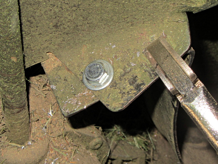
In the course of normal events around here, the M2 gets tipped to one side or the other. Every time that happens, I rediscover the blindingly obvious fact that there’s nothing holding the glass build plate and the heater to the support spider:

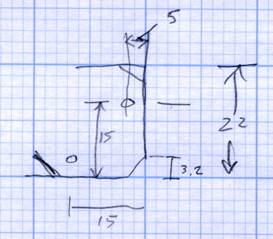
A few minutes with a metric ruler produced some useful dimensions for the ends of the spider’s arms:
The Big Box o’ Foamy Things emitted a mouse pad (remember mouse pads?) of exactly the right thickness to bring the corner pads just barely above the level of the glass plate, thus allowing for slight compression:
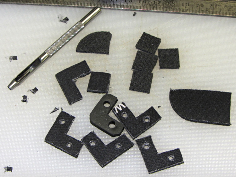
That’s a 1/8 inch hole punch, which is close enough to the M3 screw diameter in foam rubber. It worked fine for the balls in the corner support pads, too.
The long-suffering shop scissors produced results about as pretty as one might expect:

Which is to say, not very.
The material is 6 mil (about 0.15 mm) phosphor bronze, nice and springy. Combined with ripply edges and sharp corners, you get perfectly serviceable serrated knife blades suitable for use in traditional shop ceremonies of ritual scarification of the fingertips.
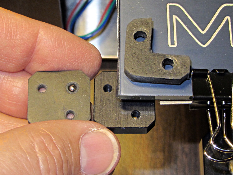
I stacked the slips, clamped them to the Sherline’s table between sacrificial plastic sheets, used manual CNC to poke a pair of #31 holes (0.120 inch, about the right clearance for M3 screws) at the right spots, and then stacked everything up on the M2:

The alert reader will notice a third #31 hole at the wrong spot, which was the first one I drilled and partially explains the lack of pictures of the operation.
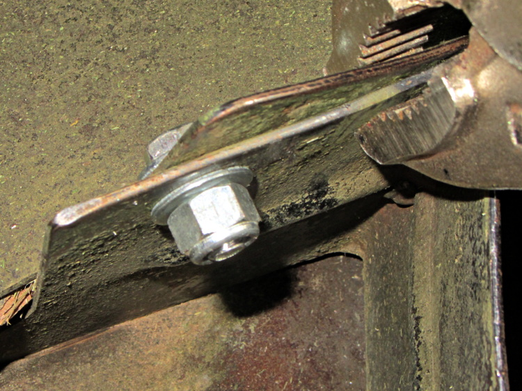
Sighting across the platform shows that the clip doesn’t lie quite flat on the glass, due to the scissors-cut bending:
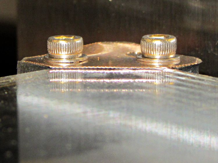
However, four of these clips hold the glass firmly to the heat spreader and eliminate the need for the stock bulldog clips, which is what I wanted to find out.
But they’re ugly and I don’t want to explain that extra hole…