Ed Nisley's Blog: Shop notes, electronics, firmware, machinery, 3D printing, laser cuttery, and curiosities. Contents: 100% human thinking, 0% AI slop.
The trio of batteries I built for the Sony DSC-F505V two years ago faded away; that camera seems particularly hard on the batteries, perhaps because they’re two cells in parallel that don’t share well. Two of the three seem pretty well gone:
Sony NP-FS11 2011 Packs – 2013-11 tests
Back then, I bought 12 cells, built six into those batteries, and left six charged cells sitting in a bag. After rebuilding the two worst batteries with those new-old-stock cells, it seems they maintained a substantial fraction of their charge while resting in the cool and the dark:
Sony NP-FS11 2011 Cells – 2013 packs – 2013-11-24
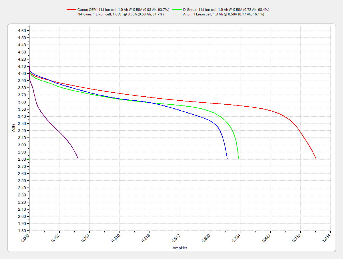
However, the camera would regard them as discharged, because it infers charge state from voltage. Squinting at the curves, their condition after a few minutes is roughly equal to a new & freshly charged battery produces over on the right when it’s nearly discharged.
The other curves show the result after their first charge in two years: basically, full capacity. The fact that both pairs of curves come pretty close to overlaying means they’re still well matched.
Sony NP-FS11 batteries – rebuilt
The third cell isn’t up to their spec, but it’s close enough to not bother rebuilding right now: 1.2 vs 1.4 A·h.
The Kapton tape pull tabs work wonderfully well, as the rebuilt batteries fit the compartment rather more snugly than the un-hacked cases.
One of the junker NB-5L eBay batteries for my Canon SX-230HS pocket camera gave up, but the other two have some usable capacity left. The OEM Canon battery seems to be doing fine, perhaps because it sees a relatively low duty cycle:
The general idea is to reduce the capacity of a 13 round Browning Hi-Power magazine to 10 rounds, in compliance with the NY Safe Act, using a number of possibly invalid assumptions. The new Firearms tag will produce earlier posts.
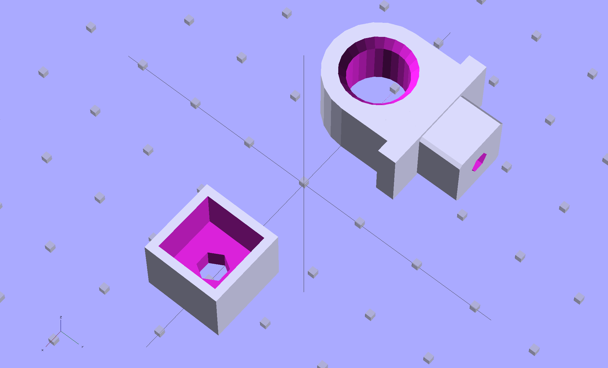
This early prototype tried out the sizes, shapes, and angles, using an M3x0.5 socket head cap screw:
The bottom nut trap locates the block on the inner floor plate by capturing the nut. It might need a bit more clearance or a chamfer to allow for brazing material around the nut flats; cleaning up the brazed nut with a file might also help.
The central trap holds a nut that anchors the block; the trap must be about 50% longer than the nut to allow for thread alignment, because the central hole is a loose tap fit.
That central nut probably isn’t needed, because you’d fill the central shaft with metal-loaded epoxy, which would form a perfectly serviceable, exactly form-fitting, and utterly non-removable “nut”. The vent from the end of the screw shaft releases air trapped behind the epoxy by the screw; if you don’t have a vent, then air pressure will force the epoxy out of the cavity.
If the epoxy “nut” is workable, then you can build it in a single piece printed vertically on the platform. Having a split version makes it easier to show off and, in truth, the cemented joint is about as strong as the rest of the object.
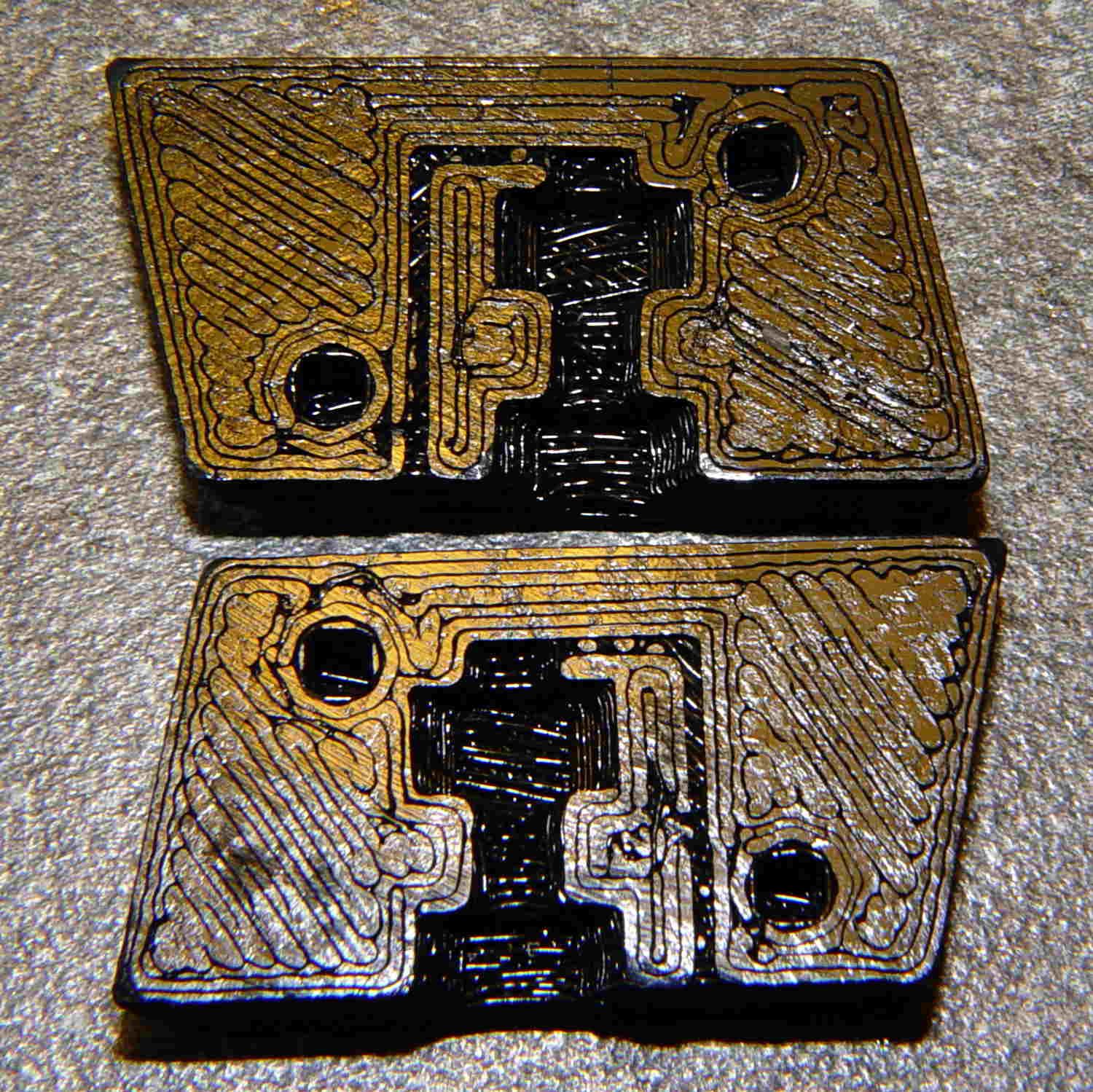
Hot off the M2 3D printer, it looks like this:
BHP magazine block – prototype nut trap – bare
A few threads droop into the air vent, so that channel should be larger. The overall plastic block may be porous enough to release the air pressure even without a vent.
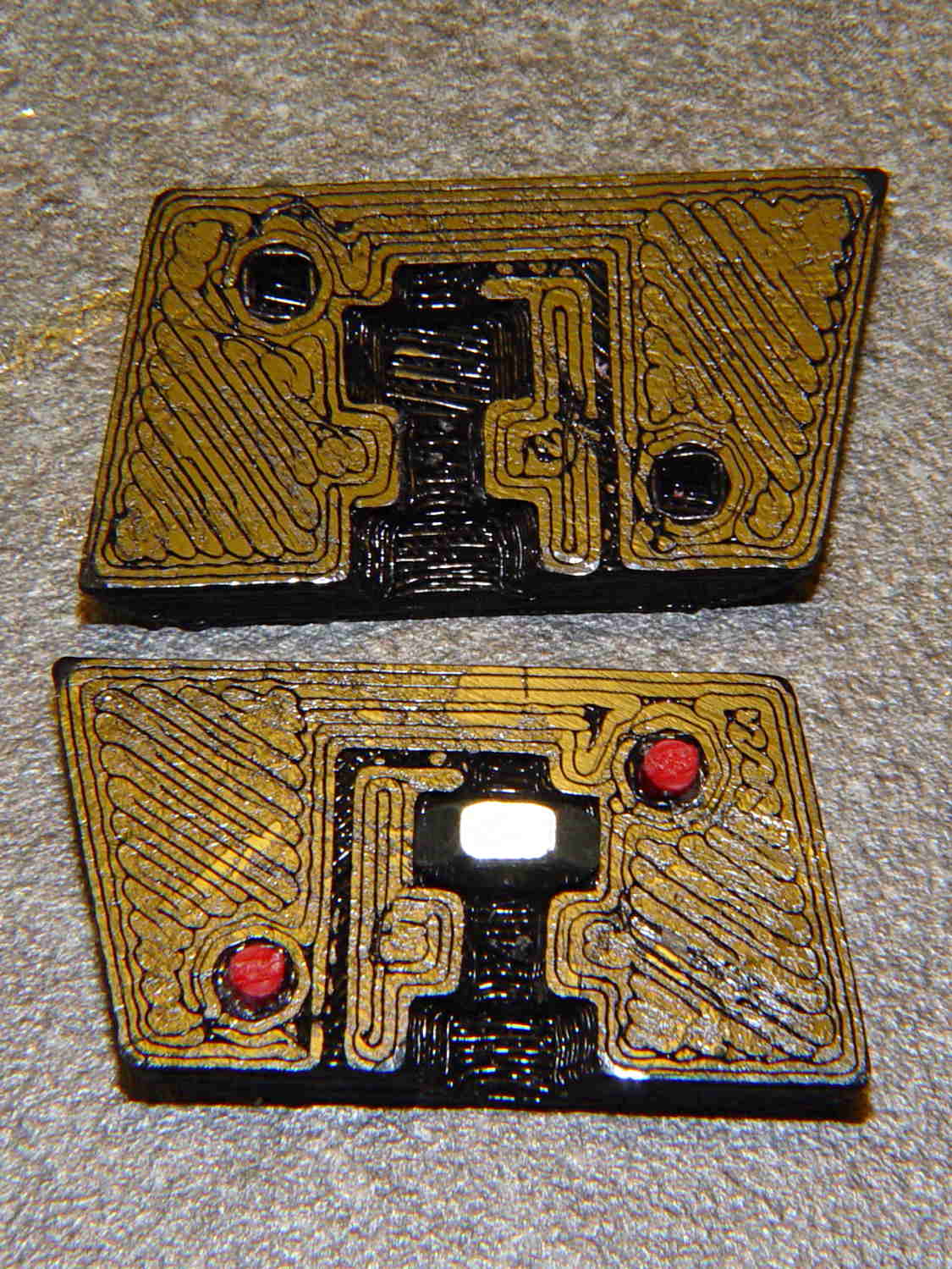
With locating pins glued in place and a nut in the central trap:
BHP magazine block – prototype nut trap
Pretty much as I expected, it doesn’t quite fit in the magazine, because it doesn’t have clearance for the little tab on the inner floor plate that captures the spring.
One might argue that a plastic block isn’t “permanent”, but it’s definitely not “readily” removed:
PLA doesn’t dissolve in common solvents
It doesn’t actually melt and flow away at high temperatures
It’s protected by the spring and inner floor plate
It’s certainly strong enough to resist simple mechanical attacks
This is a start…
The OpenSCAD source code, replete with inadequacies:
// Browning Hi-Power Magazine Plug
// Ed Nisley KE4ZNU November 2013

Layout = "Show";			// Show Whole Pin Build

CrossSection = 1;			// -1, 0, 1 to select section side or none

Section = (Layout == "Build") ? 1 : CrossSection;		// for cross-section for build

//- Extrusion parameters must match reality!
//  Print with 2 shells and 3 solid layers

ThreadThick = 0.25;
ThreadWidth = 0.40;

HoleWindage = 0.2;

Protrusion = 0.1;			// make holes end cleanly

//----------------------
// Dimensions

Angle = 12.5;				// from vertical

EndDia = 10.3;				// an 11/32 inch drill fits
EndRadius = EndDia / 2;

Length = 24.0;				// front-to-back perpendicular to magazine shaft
Height = 14.0;				// bottom-to-top, parallel to magazine shaft
							//  14 = 10 round capacity
							//  28 = 7 round

RectLength = Length - EndDia;	// block length between end radii

ScrewOD = 3.0 - 0.5;		// bottom screw tapping diameter
ScrewLength = 11.0;
ScrewOffset = 0;			//   ... from centerline

NutOD = 5.5;				// hex nut dia across flats
NutThick = 2.4;				//  ... then add 50% for thread engagement & epoxy
NutOffset = 6.0;			//  ... base height from floor

VentWidth = 2*ThreadWidth;	// air vent from back of screw recess
VentDepth = 4*ThreadThick;

NumSides = 8*4;				// default cylinder sides

PinOD = 1.72;				// alignment pins
PinLength = 6.0;
PinInset = 0.9*EndRadius;	// from outside edges
echo(str("Alignment pin length: ",PinLength));

Offset = 5.0/2;				// from centerline for build layout

//----------------------
// Useful routines

// Locating pin hole with glue recess
//  Default length is two pin diameters on each side of the split

module LocatingPin(Dia=PinOD,Len=0.0) {

	PinLen = (Len != 0.0) ? Len : (4*Dia);

	translate([0,0,-ThreadThick])
		PolyCyl((Dia + 2*ThreadWidth),2*ThreadThick,4);

	translate([0,0,-2*ThreadThick])
		PolyCyl((Dia + 1*ThreadWidth),4*ThreadThick,4);

	translate([0,0,-(Len/2 + ThreadThick)])
		PolyCyl(Dia,(Len + 2*ThreadThick),4);

}

module PolyCyl(Dia,Height,ForceSides=0) {			// based on nophead's polyholes

  Sides = (ForceSides != 0) ? ForceSides : (ceil(Dia) + 2);

  FixDia = Dia / cos(180/Sides);

  cylinder(r=(FixDia + HoleWindage)/2,
           h=Height,
	   $fn=Sides);
}

module ShowPegGrid(Space = 10.0,Size = 1.0) {

  Range = floor(50 / Space);

	for (x=[-Range:Range])
	  for (y=[-Range:Range])
		translate([x*Space,y*Space,Size/2])
		  %cube(Size,center=true);

}

//----------------------
// Components

module Block(SectionSelect = 0) {

Delta = tan(Angle)*(Length/2);				// incremental length due to angle

CropHeight = Height*cos(Angle);				// block height perpendicular to base

echo(str("Perpendicular height: ",CropHeight));

	difference() {
		intersection() {
			rotate([Angle,0,0])
				difference() {
					translate([0,0,-Height/2])
						linear_extrude(height=2*Height,convexity=2) {
							for (i=[-1,1])
								translate([0,(i*RectLength/2),0])
									rotate(180/NumSides)
										circle(r=EndRadius/cos(180/NumSides),
												$fn=NumSides);
							square([EndDia,RectLength],center=true);
						}
					for (i=[-1,1])
						translate([0,
									(i*(Length/2 - PinInset)),
									(CropHeight/2 + i*(CropHeight/2 - PinInset))])
							rotate([0,90,0]) rotate(45-Angle)
								LocatingPin(PinOD,PinLength);
				}
			translate([0,0,CropHeight/2])
				cube([2*EndDia,3*Length,CropHeight],center=true);
		}
		translate([0,ScrewOffset,-Protrusion])		// screw
			rotate(180/6)
				PolyCyl(ScrewOD,(ScrewLength + Protrusion),6);

		translate([0,ScrewOffset,NutOffset])		// nut trap in center
			rotate(180/6)
				PolyCyl(NutOD,1.5*NutThick,6);

		translate([0,ScrewOffset,-Protrusion])		// nut clearance at base
			rotate(180/6)
				PolyCyl(NutOD,(1.1*NutThick + Protrusion),6);

		translate([0,-(ScrewOffset + NutOD),(ScrewLength - Protrusion)/2])	// air vent
			cube([VentDepth/2,VentWidth,(ScrewLength + Protrusion)],center=true);
		translate([0,(ScrewOffset - NutOD/2),(ScrewLength - VentWidth/2)])
			cube([VentDepth/2,NutOD,VentWidth],center=true);

		if (SectionSelect == 1)
			translate([EndDia,0,Height/2-Protrusion])
				cube([2*EndDia,3*Length,Height+2*Protrusion],center=true);
		else if (SectionSelect == -1)
			translate([-EndDia,0,Height/2-Protrusion])
				cube([2*EndDia,3*Length,Height+2*Protrusion],center=true);
	}

}

//-------------------
// Build it...

ShowPegGrid();

if (Layout == "Pin")
	LocatingPin(PinOD,PinLength);

if (Layout == "Show")
	Block(CrossSection);

if (Layout == "Whole")
	Block(0);

if (Layout ==  "Build") {
	translate([(Offset + Length/2),Height/2,0])
		rotate(90) rotate([0,-90,-Angle])
			Block(-1);
	translate([-(Offset + Length/2),Height/2,0])
		rotate(-90) rotate([0,90,Angle])
			Block(1);
}
Word got around quickly after I set up the bird feeder at the corner of the patio, one week before Mary’s Project Feederwatch data collection started up:
Nuthatch on patio
You can tell this chipmunk wasn’t at all bothered by my presence:
North end of southbound chipmunk
We call them fur birds, but they don’t count for Feederwatch:
Chipmunk in vacuum cleaner mode
A few days later, I put a casserole of fresh-cooked brown rice on a patio table to cool, only to have a raccoon drag it off. Of course, the Pyrex bowl shattered on the concrete: neither of us got much of the rice…
Those simple floor brush strips for the Samsung vacuum cleaner worked moderately well, but the urethane adhesive didn’t have enough grip on the plastic strips. Having just run out of that batch, I made up another set with slightly undercut holes:
Bushing Solid Model – better holes – bottom
That’s half a thread width on each side, just enough to give the adhesive something to grab. Such is the plan, anyway.
I taped the strips to a pair of credit cards (actually, flat cards without embossed characters), slathered a thin layer of urethane atop them, and laid on squares of the same wool fabric I used the last time:
Samsung vacuum floor strips – gluing
Then I piled a steel block atop an aluminum slab on both arrays, fast forwarded a day, peeled and flexed and cut the strips apart:
Samsung floor brushes – glued
The urethane foamed through the holes as I hoped and (seems to have) locked the fabric in place, at least well enough to withstand some experimental bending on the workbench.
Now, to see how they stand up to actual use…
The OpenSCAD source code:
// Samsung Vacuum cleaner nozzle floor strips
// Ed Nisley KE4ZNU January 2013
//  November 2013 - adapt to M2, enlarge holes

Layout = "Build";			// Show, Build

//- Extrusion parameters must match reality!
//  Print with +0 shells and 3 solid layers

ThreadThick = 0.25;
ThreadWidth = 0.4;

HoleWindage = 0.75;

function IntegerMultiple(Size,Unit) = Unit * ceil(Size / Unit);

Protrusion = 0.1;           // make holes end cleanly

//----------------------
// Dimensions

Body = [6.0,59.0,3*ThreadThick];	// width, length, thick

Tab1 = [4.5,5.0,0.0];				// width, length, offset from centerline
Tab2 = [3.5,5.0,0.5];

HoleOC = 8.0;						// adhesive anchoring holes
HoleDia = 2.0;
HoleSides = 4;
HoleMax = floor(Body[1]/(2*HoleOC));

echo("HoleMax: ",HoleMax);

//----------------------
// Useful routines

module PolyCyl(Dia,Height,ForceSides=0) {           // based on nophead's polyholes

Sides = (ForceSides != 0) ? ForceSides : (ceil(Dia) + 2);

FixDia = Dia / cos(180/Sides);

cylinder(r=(FixDia + HoleWindage)/2,
         h=Height,
         $fn=Sides);
}

module ShowPegGrid(Space = 10.0,Size = 1.0) {

    Range = floor(50 / Space);

    for (x=[-Range:Range])
        for (y=[-Range:Range])
            translate([x*Space,y*Space,Size/2])
            %cube(Size,center=true);

}

module BackingStrip() {

	difference() {
		union() {
			translate([0,0,Body[2]/2])
			cube(Body,center=true);
			translate([Tab1[2],-1*Body[1]/2,Body[2]/2])
			cube([Tab1[0],2*Tab1[1],Body[2]],center=true);
			translate([Tab2[2],+1*Body[1]/2,Body[2]/2])
			cube([Tab2[0],2*Tab2[1],Body[2]],center=true);
		}
		for (i = [-HoleMax:HoleMax])
			translate([0,i*HoleOC,-Protrusion])
			rotate(45) {
				PolyCyl(HoleDia,(Body[2] + 2*Protrusion),HoleSides);
				PolyCyl((HoleDia + ThreadWidth),(ThreadThick + Protrusion),HoleSides);
			}
	}
}

//----------------------
// Build it!

ShowPegGrid();

if (Layout == "Show")
	BackingStrip();

if (Layout == "Build")
	rotate(90) BackingStrip();
We don’t drive the van nearly often enough (*) to keep the battery charged in cold weather, so I use a trickle charger to keep it alive between jaunts. While opening the hood one evening, I managed to twist the plastic fitting that anchors the hood prop rod beyond its limits and snapped the poor thing off, which left me holding the hood in one hand and the rod in the other.
After extricating most of the fragments from under the van, I found that the OEM part had a hollow post that snapped into a square hole in the front bulkhead under the hood. The post had two keys and a pair of snap latches that held it in place, a design that seemed optimized for rapid assembly with no fiddly parts, but which depended on a few millimeters of plastic to restrain a meter of steel rod.
I made up a simple replacement with a solid square post and a square cap to clamp it against the bulkhead:
Toyota Sienna hood rod pivot – first version
The general idea is that the screw puts the entire post under compression, giving it less temptation to shear at the deck line when I twist the rod a bit too far out of line. That 8-32 screw seemed entirely adequate to the task; a 10-32 screw would take up too much of the post for my liking.
Alas, it turns out that underneath the bulkhead’s top flange lies a metal plate surrounding the headlight that’s so close to the hole that the big blocky cap wouldn’t fit. So I slimmed the cap down to three thread widths and tried again, only to discover that the plate came that close to the edge of square hole.
However, there was a gap between the bottom of the bulkhead and the top of the plate, so I introduced pivot and cap to Mr Belt Sander, removed enough plastic to let the cap slide into the gap, then discovered the 8-32 screw head was just slightly too large to let the screw align with the post.
Another tweak to the model, based on actual measurements on the abused parts, produced the final version:
Toyota Sienna Hood Rod Pivot – solid model
The rod hole has a nice bevel, there’s no fragile neck between the rod hole and the base flange, the solid post lies flat on the platform for EZ building, and there’s a slight offset between the post and the flange that eliminates the need for support material. Printing it lying down orients the filament paths around the hole and base, making the part stronger in the direction it needs the most strength.
I think the cap walls could be slightly thicker, but we’ll see how long the thing lasts…
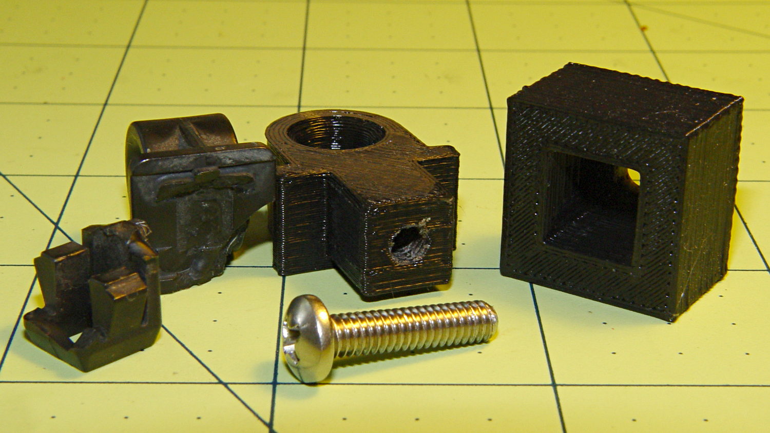
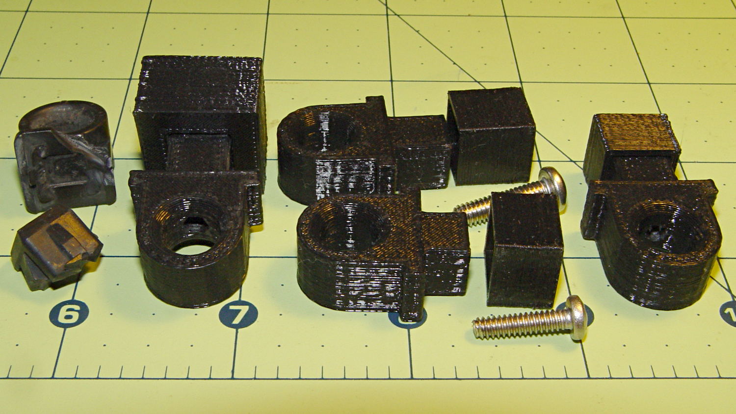
A group photo of all the versions, lined up from left to right, shows the broken OEM part, the first blocky attempt, the slimmed-down and too-long version to the rear, the shorter version that actually fit, and a backup part for when that one breaks:
Toyota Sienna hood rod pivot versions
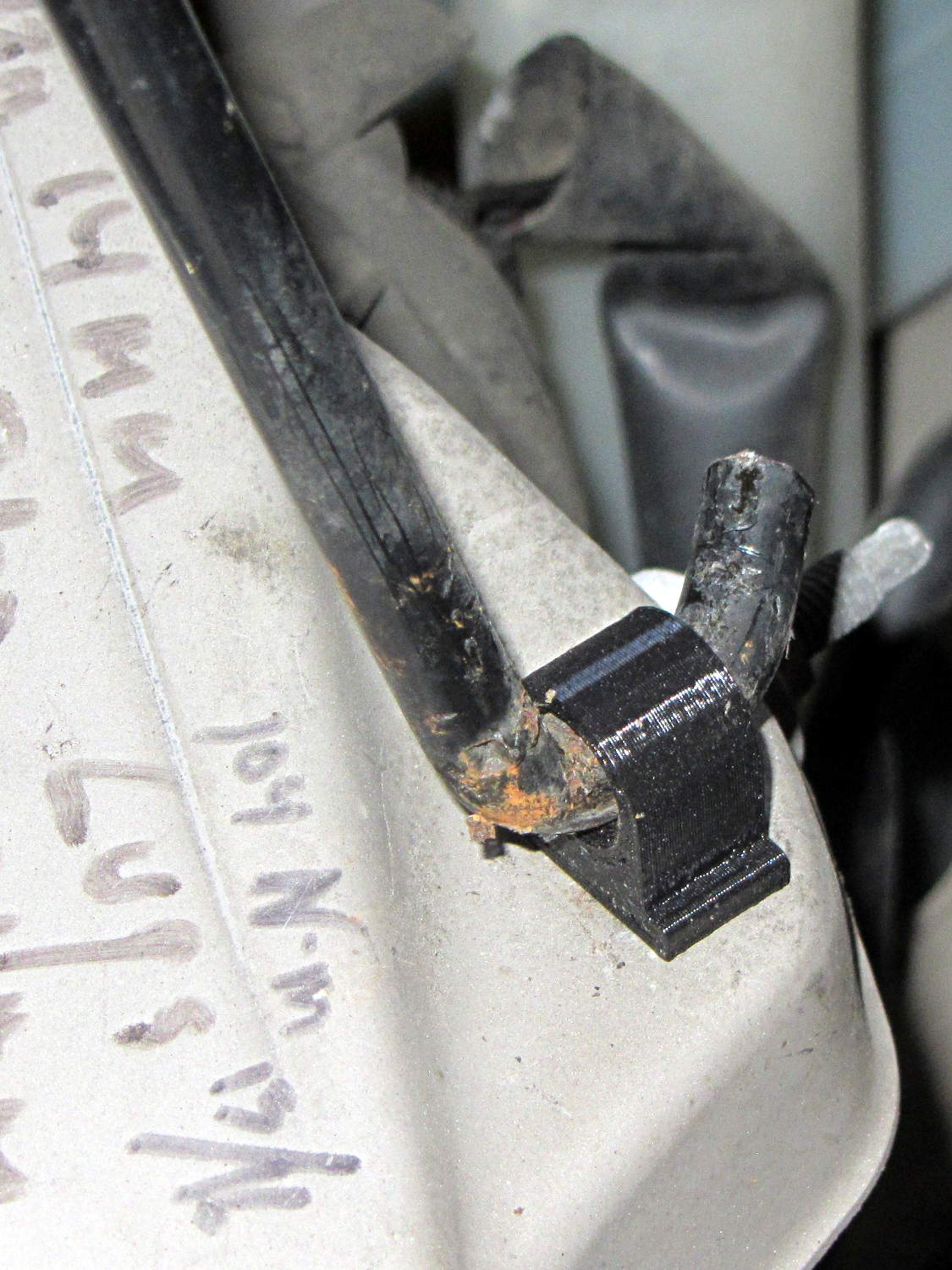
The sanded-down part held the hood open while I took that group picture. Here’s what it looks like under load:
Toyota Sienna hood rod pivot – in place
The scrawls on the bulkhead just in front of the pivot remind me of fluid levels, torques, and suchlike. The stud sticking out to the rear is a headlight aiming screw mounted in the plate that caused so much hassle; you’d think I’d have noticed it before starting this adventure, but noooo…
For what it’s worth, that’s rapid prototyping in action: three (and a half) iterations in quick succession, each getting closer to a goal that you (well, I) can’t quite define, but will recognize when it appears. Took about three hours over the course of two days.
I loves me my M2 3D printer…
(*) Indeed, the tires often take three miles to warm up their flat spots due to sitting in the garage for a week…
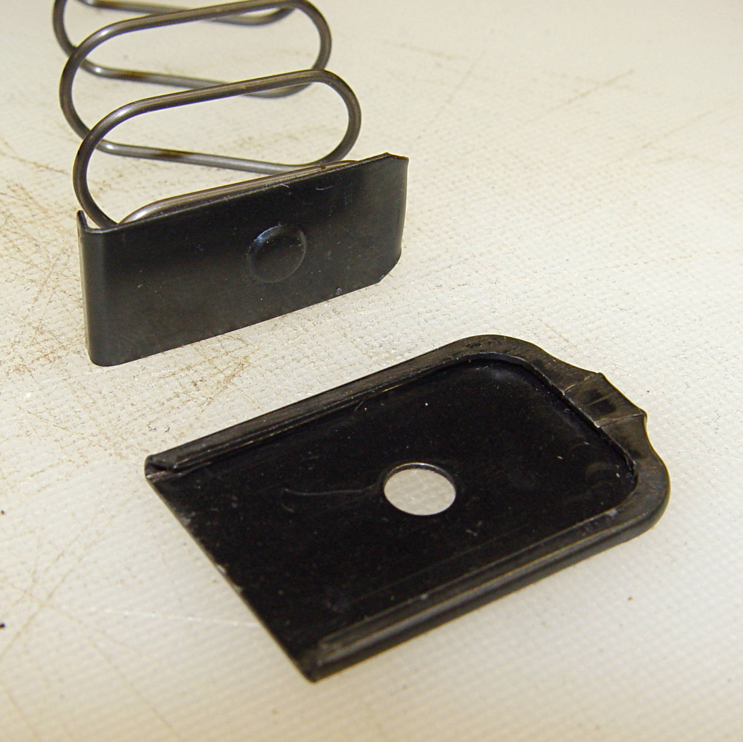
The Browning Hi-Power magazine has two floor plates:
the interior plate captures the spring and locates it properly inside the magazine case
the exterior plate provides reaction force against the spring and locates the interior plate’s boss
Browning Hi-Power magazine – base plates
The interior plate has two critical features:
the ramp on the front (to the right) that guides it over the edge of the exterior plate
the boss that latches the exterior plate in place
If you remove the interior plate, you must somehow hold the spring in place while sliding the exterior plate in place, after which the spring is free to thrash around inside the magazine under recoil forces.
An important point: you can buy exterior floor plates from all the usual sources, but, as nearly as I can tell, nobody sells replacement interior floor plates and they’re not included in kits of replacement springs. If you don’t have an interior floor plate, you must fabricate one from scratch before you can use the magazine.
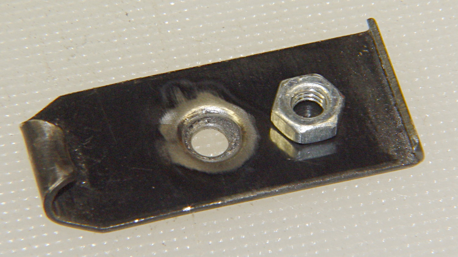
So one thought is to drill a hole in the middle of the boss:
Browning Hi-Power magazine – drilled floor plate
OK, that’s not quite centered, but it’ll suffice.
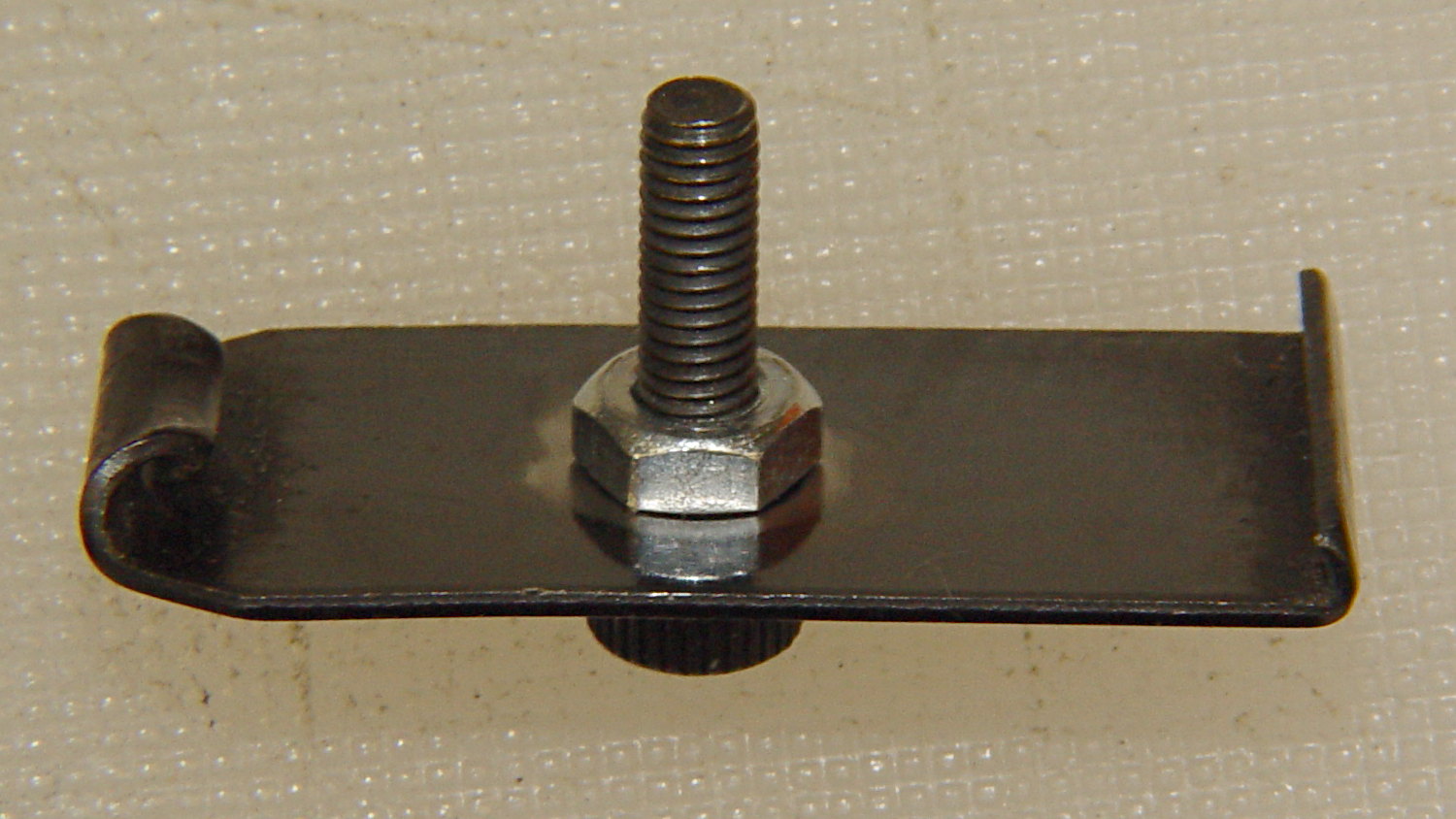
Wire-brush the coating around the inside of the boss to prepare it for brazing, then braze a nut onto the inside of the floor plate (which I haven’t done yet), and run a socket-head setscrew through it:
Browning Hi-Power magazine – drilled floor plate
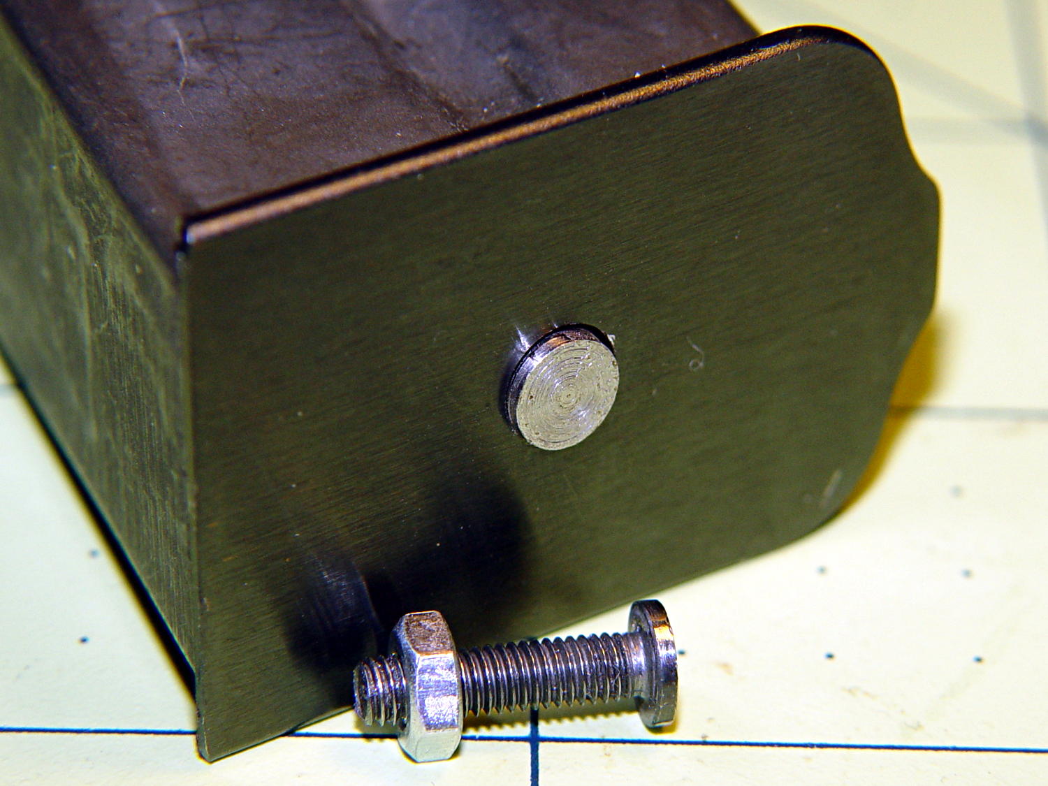
If that threaded into a block loaded with steel-filled epoxy, it’d never come back out again. You could machine the head down to a flat disk that would fit through the existing hole in the exterior floor plate and not provide any gripping surface:
BHP floor plate screw – disk head
To be absolutely certain, you could file the entire socket head off flush with the boss, leaving no way to grip the screw.
If the block surrounds the nut on the floor plate with a generous helping of steel-filled epoxy, then there’s no way to twist the block off the plate.
If the block also captures the spring, then you can’t heat the plate enough to un-braze the nut without also de-tempering and wrecking the spring.
I can think of a few other ways to attack it, but none seem like a project that would readily convert the magazine into one holding a few more rounds. Opinions may differ, of course, but …