Ed Nisley's Blog: Shop notes, electronics, firmware, machinery, 3D printing, laser cuttery, and curiosities. Contents: 100% human thinking, 0% AI slop.
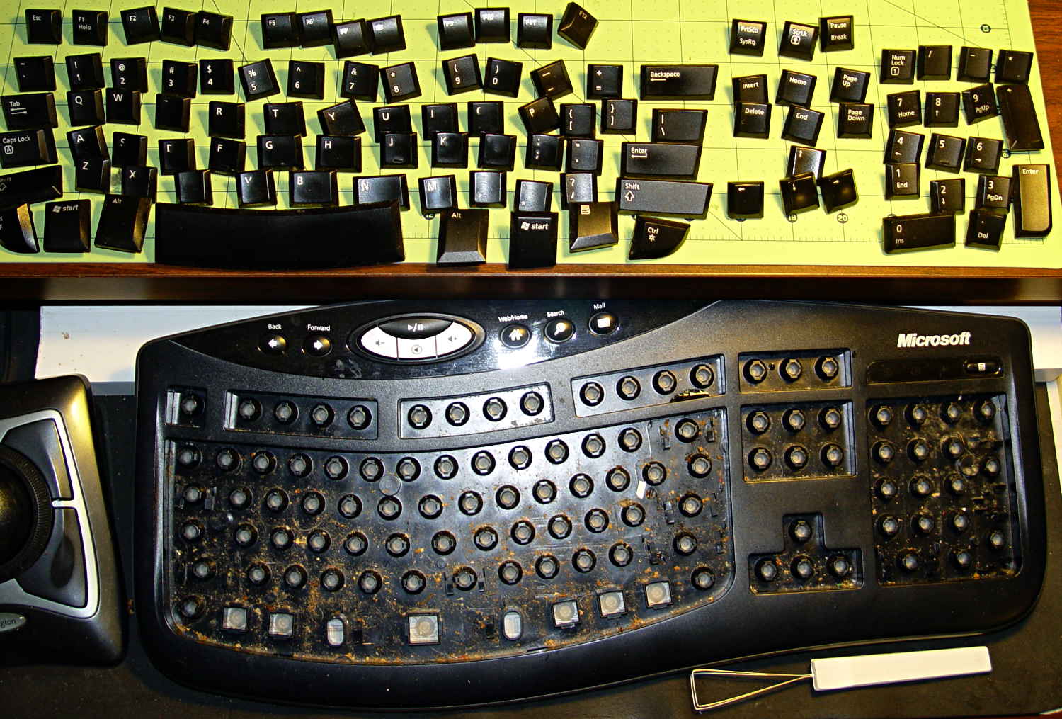
Part of the routine cleaning around here involves running the vacuum cleaner nozzle over the keyboard to suck up random debris, but that doesn’t extract crud from under the keycaps. Almost exactly three years after the previous cleaning, I finally decided the keys had lost enough of their normal feel to justify the hassle of taking the thing apart.
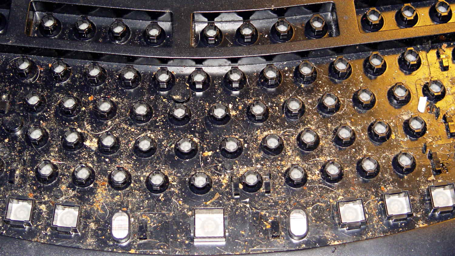
Bolstered by that experience, however, I just yanked the keycaps off with a removal tool from my old bag of tricks, revealing the horror that lies beneath the surface:
The keycaps took a swim in a dishpan full of hot soapy water, endured some scrubbing, and emerged looking like new. Thwacking them on a towel ejected the remaining water from the posts.
With the electronics still in place, I vacuumed the larger chunks out of the tray, scrubbed the aforementioned hot soapy water around the bushings with an acid brush, then cleaned up the residue with cotton swabs. There’s a paper towel under the drain gutters to catch the runoff, which worked surprisingly well.
The keycap legends have been eroding, as they’re basically a decal stuck on the surface. Eventually I’ll have a crappy non-clicky Das Keyboard Model S Ultimate.
[Update: a spammer’s script has been attempting to create hundreds of junk comments per day, so I’ve temporarily disabled comments for this post. Drop me a direct note using the About / Copyright / Contact link on the right if it’s critical. I expect this to pass in a few days, but I may be underestimating the stupidity out there. ]
A note from regular commenter Frans:
Don’t get a Das Keyboard if you want a keyboard without a keypad. Look into e.g. a Leopold Tenkeyless Otaku. The one to which I include a link comes with the same Cherry MX Brown switches as the Das Keyboard Silent.
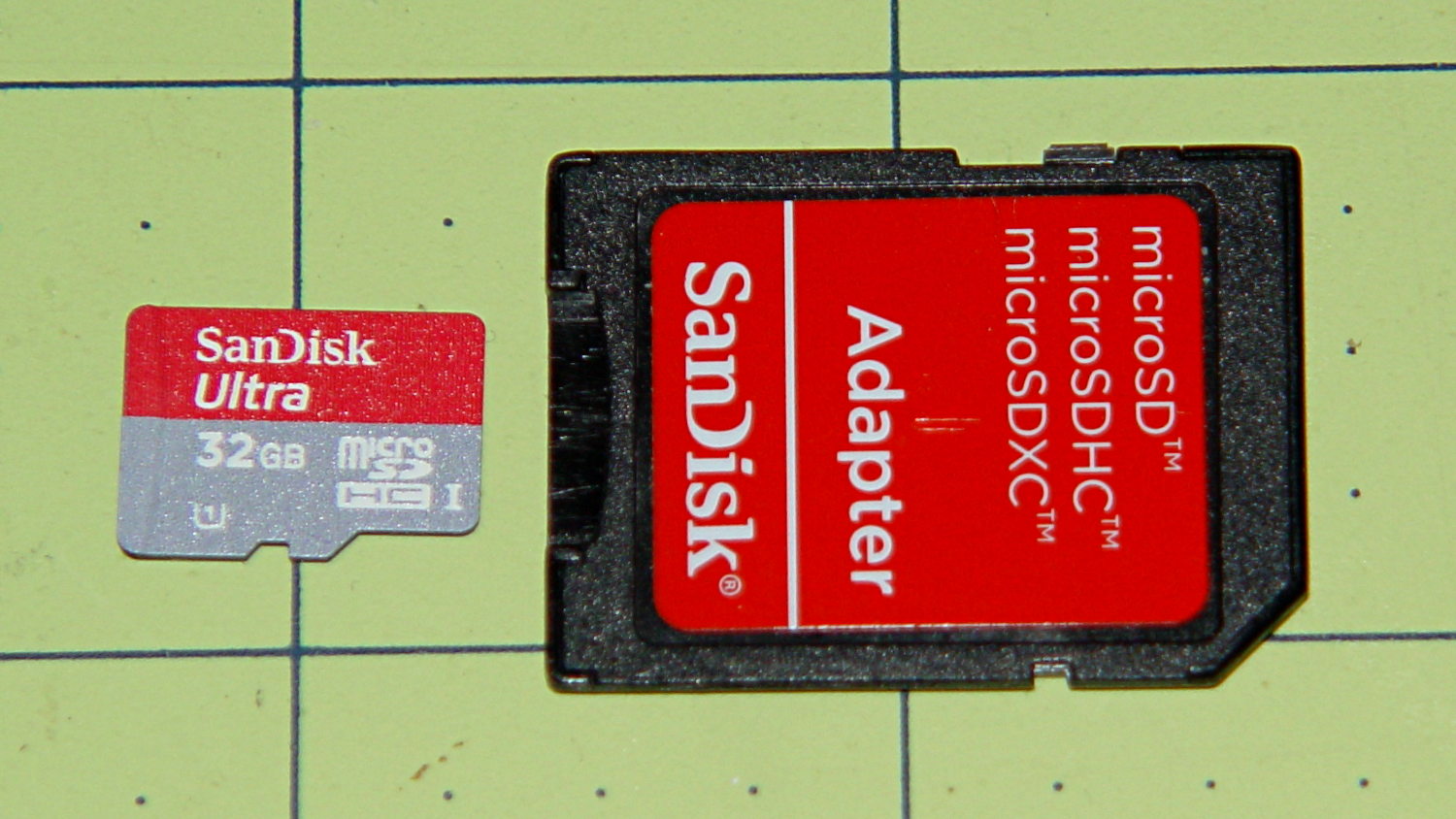
Picked up a Sandisk 32 GB Micro SD Card from a reputable supplier for $0.62/GB, in the hope that Santa will deliver a helmet camera:
Sandisk 32 GB microSD card
Until that happy event, I verified that it can store and return 32 GB of white noise with absolute fidelity.
It came formatted with an empty FAT32 filesystem that allows single files up to 4 GB. Reformatting with exFAT supports vastly larger capacities and, in this case, allows single files up to 32 GB. Whether it’s actually legal to use exFAT on a Linux box remains up for grabs, but installing exfat-utils, which drags in exfat-fuse, does the trick.
Verifying the SD Card capacity went swimmingly, much along the lines of the original recipe. The data file size came from the card’s FAT-32 formatting and is a smidge less than the capacity after reformatting the card with exFAT. Close enough for this purpose.
dd bs=1K count=31154656 if=/dev/urandom of=/mnt/part2/Testdata/Testdata.bin
(This took the better part of an hour; I didn't record it.)

sudo mkexfatfs -i babeface -n SanDisk32GB /dev/sdb1
mkexfatfs 1.0.1
Creating... done.
Flushing... done.
File system created successfully.

sudo dumpexfat /dev/sdb1
dumpexfat 1.0.1
Volume label             SanDisk32GB
Volume serial number      0xbabeface
FS version                       1.0
Sector size                      512
Cluster size                   32768
Sectors count               62325760
Free sectors                62317504
Clusters count                973719
Free clusters                 973711
First sector                       0
FAT first sector                 128
FAT sectors count               7616
First cluster sector            7744
Root directory cluster             7
Volume state                  0x0000
FATs count                         1
Drive number                    0x80
Allocated space                   0%

time rsync --progress /mnt/part2/Testdata/Testdata.bin /mnt/part/Test.bin
Testdata.bin
 31902367744 100%    9.15MB/s    0:55:24 (xfer#1, to-check=0/1)

sent 31906262150 bytes  received 31 bytes  9594425.55 bytes/sec
total size is 31902367744  speedup is 1.00

real	55m25.791s
user	3m16.088s
sys	2m7.808s

df -h /mnt/part
Filesystem      Size  Used Avail Use% Mounted on
/dev/sdb1        30G   30G  4.0M 100% /mnt/part

time diff /mnt/part2/Testdata/Testdata.bin /mnt/part/Test.bin

real	28m43.878s
user	0m4.044s
sys	0m42.902s

ll /mnt/part/Test.bin
-rwxr-xr-x 1 ed root 31902367744 Dec  2 18:32 /mnt/part/Test.bin*

rm /mnt/part/Test.bin

df -h /mnt/part
Filesystem      Size  Used Avail Use% Mounted on
/dev/sdb1        30G  4.1M   30G   1% /mnt/part
I’m probably easily impressed, but wow that’s a lot of data in a little chip of plastic… for $20 delivered.
Although the Optiplex 780 continues to chug along, some additional bringup notes for the new-to-me Optiplex 980 may be of future use. In no particular order, because that’s how it goes:
The OS is Xubuntu 13.10 in the 64-bit flavor, mostly for UI & infrastructure consistency with my other boxes. The Ubuntu project continues to diverge from consensus reality and the process of fighting down the Special Ubuntu Sauce seems increasingly difficult and less rewarding. This may be the last box I set up with Xubuntu, although I’m not sure what else to use; Arch requires more fiddly sysadmin-fu than I’m willing to allocate and Ubuntu-based distros like Mint seem to have all the disadvantage of Ubuntu plus the difficulties of splinter distros.
With two cores and HyperThreading turned on, it has enough moxie to run one instance of the GIMPS prime factoring code without crippling the UI. The estimated completion date for the current work is 9 July 2014, which should creep closer as the CPU sees more uptime. The previous crontab startup continues to work. It adds about 25 W to the baseline 50 W consumption.
Adobe has abandoned Adobe Reader for Linux and attempting to install the most recent version of 9.whatever produces a blizzard of warnings. I’ll try Okular and Evince, although both have problems with some PDFs that Reader handles with aplomb. Eliminating the security exposures in Reader should be a net win.
Okular gets its own devilspie2 rule that look a lot like the previous one for Adobe Reader:
if (string.find(get_window_name(),"Okular")) then
      unmaximize();
      set_window_geometry(0,0,1000,100);
      set_window_geometry(2561,0,1000,100)
      maximize();
end
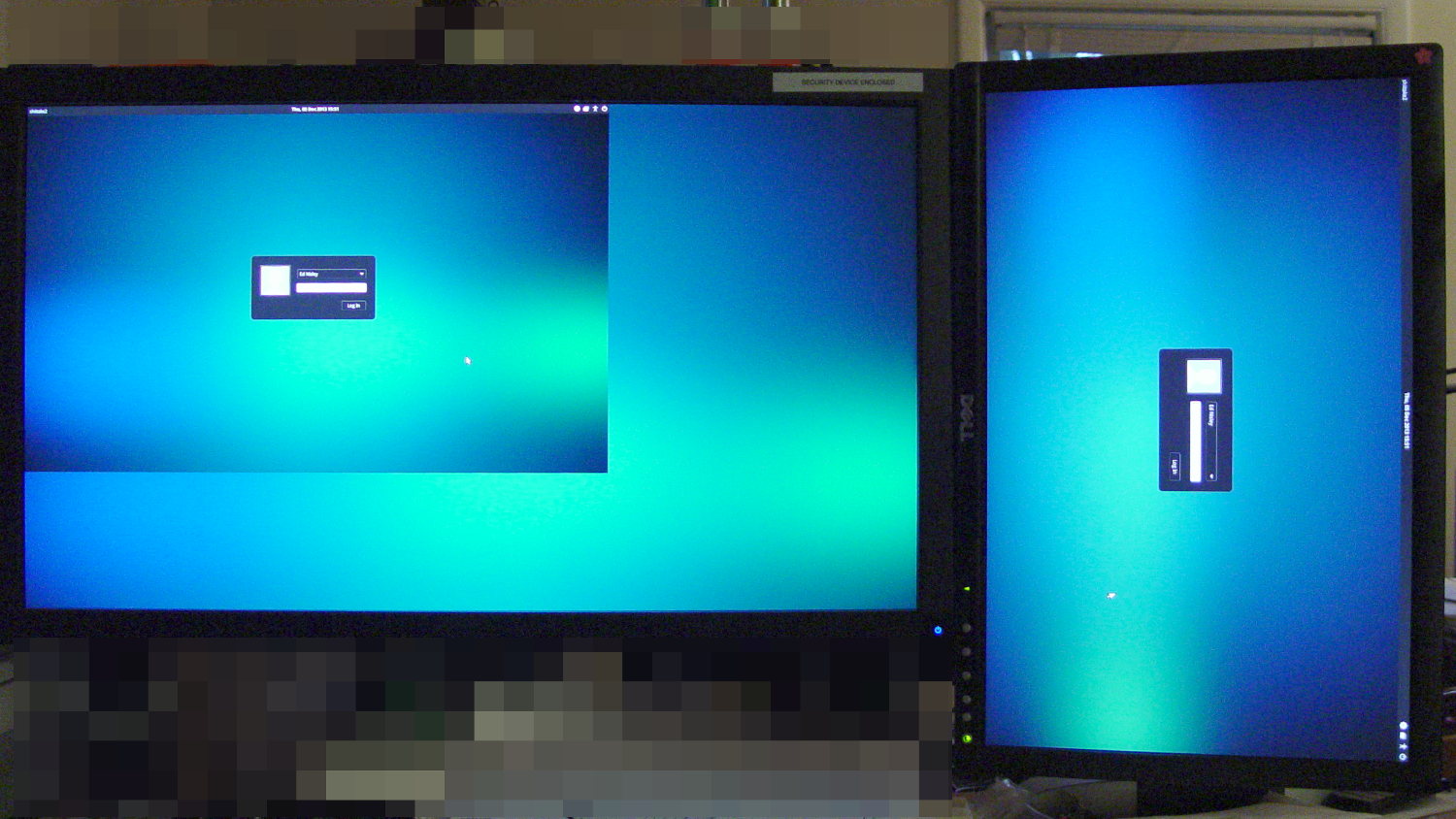
This Optiplex 980 has two built-in video connectors (DisplayPort and VGA) that work with the Free Software drivers. After some fumbling around, the XFCE Display configuration utility positioned and rotated the landscape and portrait monitors as I wanted them. Running the 1680×1050 display with analog VGA signals produces a noticeably less crisp result, but it’s on the OK side of Good Enough.
The startup display / greeter doesn’t handle that configuration very well at all:
Xubuntu greeter – dual displays
The .xprofile file doesn’t need the xrandr hacks and includes the display names corresponding to the new video outputs:
setxkbmap -option terminate:ctrl_alt_bksp
#xrandr --output HDMI-0 --rotate left
#xrandr --dpi 100x100
xsetwacom --verbose set "Wacom Graphire3 6x8 stylus" MapToOutput "DP1"
xsetwacom --verbose set "Wacom Graphire3 6x8 eraser" MapToOutput "DP1"
Although I’m sure there’s a Better Way that’s now The Standard Method, just creating a simple /etc/X11/xorg.conf file (with nothing else!) swapped the Kensington Expert Mouse buttons:
Perhaps that should be in a file tucked in /usr/share/X11/, along with 50-wacom.conf, which I modified to swap the stylus buttons, which worked the last time:
The default audio stream goes through DisplayPort and comes out of the monitor’s audio jack, which took an embarassingly long time to discover. As nearly as I can tell, there is no way to enable the internal audio in addition to the DisplayPort channel; putzing with pavucontrol and alsamixer was unproductive.
The “indicator applet” sound control seems to be irrecoverably broken, for reasons having to do with the change from GTK2 to GTK3 (or something like that); the suggested workaround do not work for this system. Unfortunately, XFCE allows exactly one mixer applet in the panel, which will pose a problem with the USB headset I use for phone calls.
I think having the local.conf routine emit a unique signal after mounting the NFS shares, then having the lightdm.conf routine wait for that signal, might just do the trick. More research is needed.
Of course, a release or two ago the tried-and-true network interface names changed, for well and good reason, but … OK, I can use em1 instead of eth0, although I sure hope that’s not a random outcome.
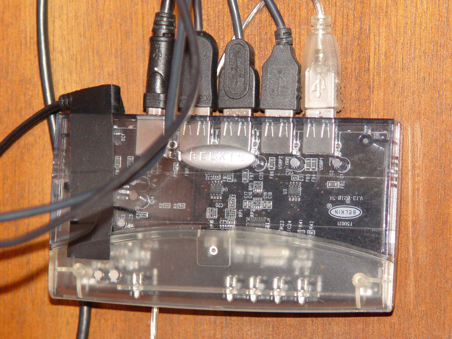
En passant, I discovered why the keyboard didn’t respond during boot: a crappy powered USB2 hub wasn’t working quite right. Swapping in an ancient Belkin powered USB hub solved that problem:
Belkin USB Hub – under desk
The hub concentrates the desktop peripherals (keyboard, two trackballs, and the tablet), so it doesn’t need high-speed throughput or responsiveness.
While the rest of the Master Gardener tour group walked on to the Island, I lay face-down on the Channel Bridge at Innisfree for a frog’s eye perspective:
Innisfree water lilies – stages
Painting these pastels would pose a challenge:
Innisfree water lily – pink
Hand-held with the Sony DSC-H5 on an overcast day that accentuated those colors.
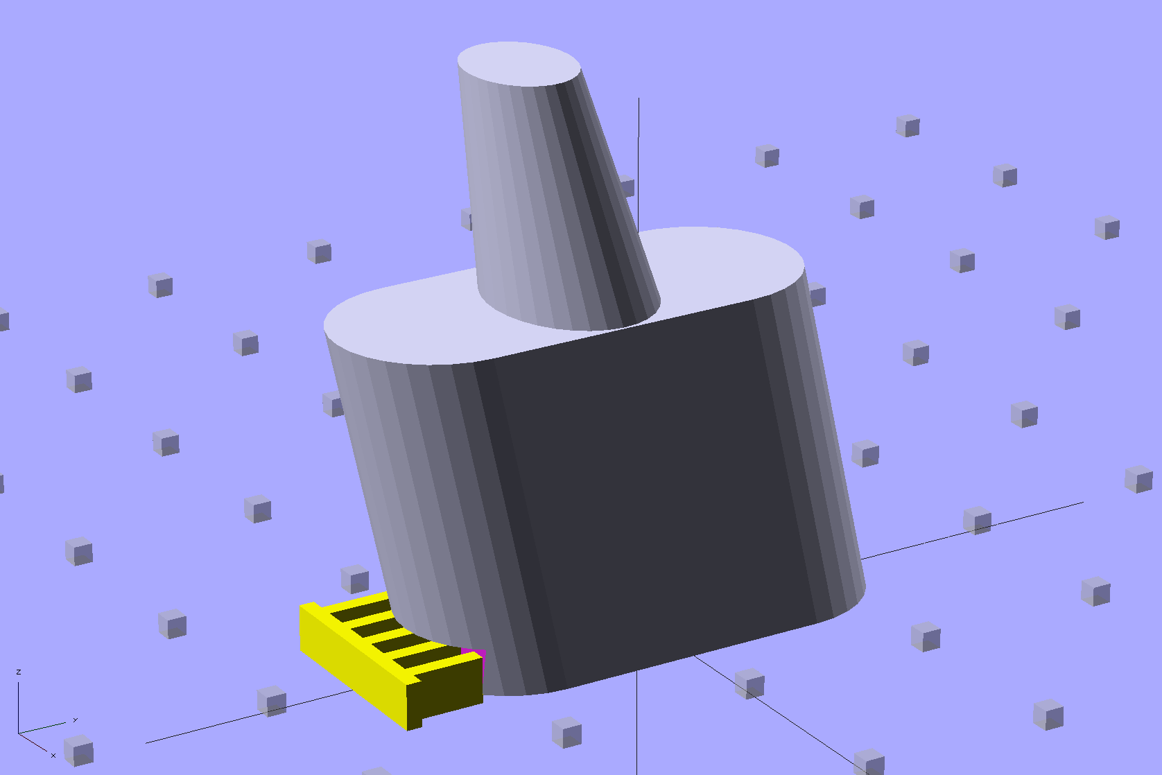
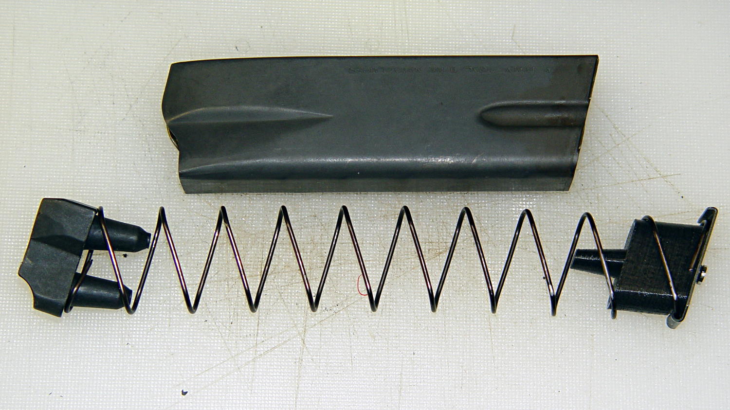
Browning Hi-Power Magazine Block – solid model – whole
The horn fits between the follower’s pegs, so that chopping the pegs off won’t increase the magazine’s capacity. Chopping the horn off without modifying the follower won’t make any difference, either. As nearly as I can tell, chopping the pegs off the follower will destabilize it enough that it’ll roll over atop the spring, but I admit to not actually trying that.
The yellow comb supports the overhang that captures the tab around the magazine spring and there’s a tiny support spider inside the lower nut clearance that holds the ceiling in place:
Browning Hi-Power Magazine Block – solid model – section
The inner nut trap probably droops a bit without any support, but there’s no way to tell when it’s printed as one solid piece. That trap will hold the blob of steel-filled epoxy that secures the screw and helps prevent the block from turning, so it’s not really a nut trap and doesn’t require a precision fit. The vent tube from the top of the screw shaft gives the air and any excess epoxy an exit path.
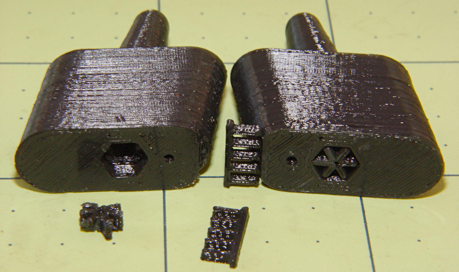
Here’s a bottom view of two blocks, showing the support structures and the results:
Browning Hi-Power magazine – block support detail
I poked the tips of a snap ring pliers into the spider and twisted it out. The comb snaps off with fingernail pressure.
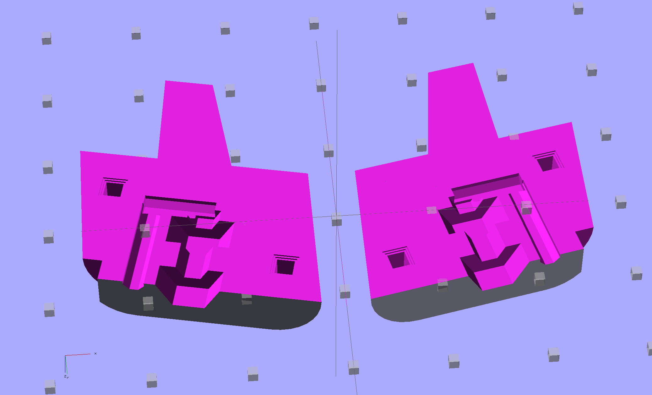
You could also print it without support by laying it flat, then glue the halves together with alignment pins. This is a bottom view:
Browning Hi-Power Magazine Block – solid model – split bottom
The OpenSCAD program has a handful of configuration settings that determine which of those blocks it produces, which components appear, and how it’s oriented.
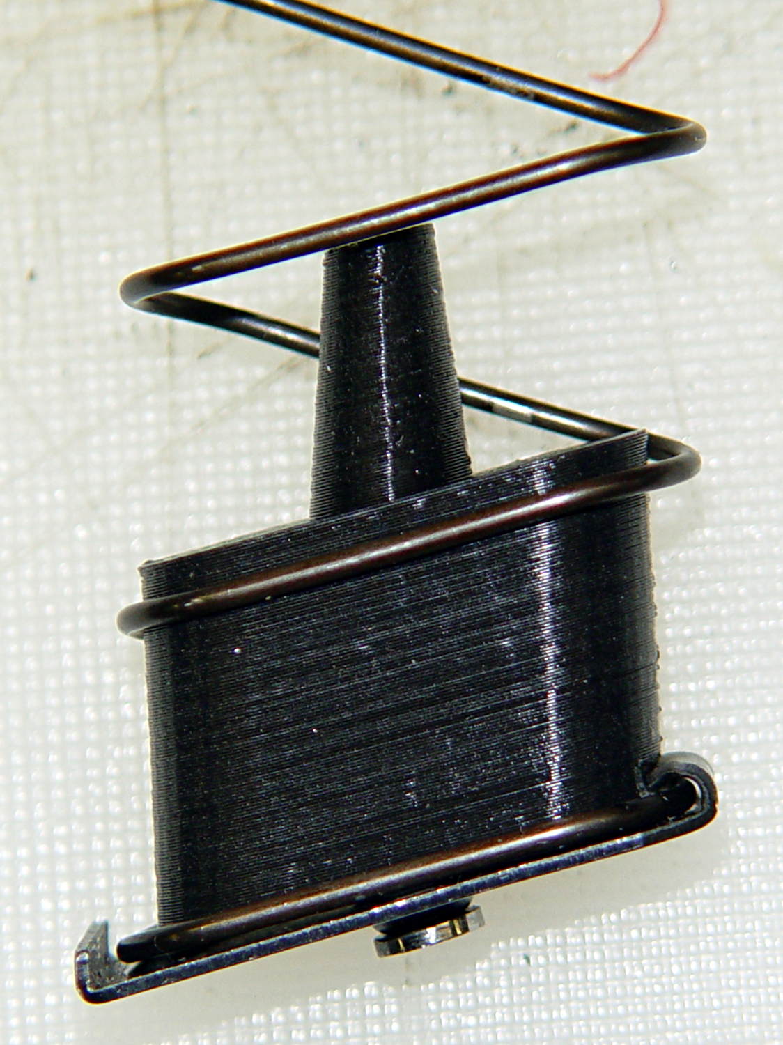
Installed in a Browning magazine, the block looks like this:
Browning Hi-Power magazine – block in place
A detail of the bottom shows the notch capturing the spring tab:
Browning Hi-Power magazine – block detail
I think the top surface would benefit from a small bevel to ease the spring around the block, but that’s in the nature of fine tuning.
Not having heard back from my legislators yet, I still don’t know whether this counts as a readily reversible modification. I have my doubts, what with it being plastic and all, but we shall see.
The OpenSCAD source code:
// Browning Hi-Power Magazine Block
// Ed Nisley KE4ZNU December 2013

Layout = "Whole";			// Show Whole Split
							//  Show = section view for demo, not for building
							//  Whole = upright for steel or plastic
							//  Split = laid flat for plastic show-n-tell assembly

AlignPins = (Layout == "Split");					// pins only for plastic show-n-tell

Support = (Layout != "Split");						// no support for split

//- Extrusion parameters must match reality!
//  Print with 2 shells and 3 solid layers

ThreadThick = 0.15;
ThreadWidth = 0.40;

HoleWindage = 0.2;

Protrusion = 0.1;			// make holes end cleanly

//----------------------
// Dimensions

Angle = 12.5;				// from vertical

SpringID = 10.3;			// magazine spring curvature (measure with drill shank)
SpringRadius = SpringID / 2;

Length = 24.0;				// front-to-back perpendicular to magazine shaft
Height = 18.0;				// bottom-to-top, parallel to magazine shaft
							//  18 = 10 round capacity

RectLength = Length - SpringID;	// block length between end radii

HornBaseOD = 8.0;			// fits between follower pegs to prevent shortening
HornTipOD = 5.0;
HornAddTip = (HornTipOD/2)*tan(Angle);
HornAddBase = (HornBaseOD/2)*tan(Angle);
HornAddLength = HornAddTip + HornAddBase + 2*Protrusion;
HornLength = 12.0;			// should recompute ODs, but *eh*

TrimHeight = 2.5;			// vertical clearance for spring clip on base plate
							//   OEM = 2.5
							//   generic A = 2.5

TrimInset = 1.5;			// ... horizontal
							//	 OEM = 0.0
							//   generic A = 1.5

ScrewOD = 3.0 - 0.25;		// screw hole dia - minimal thread engagement
ScrewLength = 11.0;
ScrewOffset = -1.5;			//   ... from centerline
							//  OEM = 0.0
							//  generic A = -1.5

NutOD = 5.6;				// hex nut dia across flats
NutThick = 2.4;				//  ... then add 50% to trap for thread engagement & epoxy
NutOffset = 6.0;			//  ... base height from floor

VentDia = 2.0;				// air vent from back of screw recess

PinOD = 1.72;				// alignment pins
PinLength = 6.0;
PinInset = 0.6*SpringRadius;	// from outside edges
echo(str("Alignment pin length: ",PinLength));

NumSides = 8*4;				// default cylinder sides

Offset = 5.0/2;				// from centerline for build layout

//----------------------
// Useful routines

function Delta(a,l) = l*tan(a);				// incremental length due to angle

// Locating pin hole with glue recess
//  Default length is two pin diameters on each side of the split

module LocatingPin(Dia=PinOD,Len=0.0) {

	PinLen = (Len != 0.0) ? Len : (4*Dia);

	translate([0,0,-ThreadThick])
		PolyCyl((Dia + 2*ThreadWidth),2*ThreadThick,4);

	translate([0,0,-2*ThreadThick])
		PolyCyl((Dia + 1*ThreadWidth),4*ThreadThick,4);

	translate([0,0,-(Len/2 + ThreadThick)])
		PolyCyl(Dia,(Len + 2*ThreadThick),4);

}

module PolyCyl(Dia,Height,ForceSides=0) {			// based on nophead's polyholes

  Sides = (ForceSides != 0) ? ForceSides : (ceil(Dia) + 2);

  FixDia = Dia / cos(180/Sides);

  cylinder(r=(FixDia + HoleWindage)/2,
           h=Height,
	   $fn=Sides);
}

module ShowPegGrid(Space = 10.0,Size = 1.0) {

  Range = floor(50 / Space);

	for (x=[-Range:Range])
	  for (y=[-Range:Range])
		translate([x*Space,y*Space,Size/2])
		  %cube(Size,center=true);

}

//----------------------
// The magazine block

module Block(SectionSelect = 0) {

CropHeight = Height*cos(Angle);				// block height perpendicular to base
echo(str("Perpendicular height: ",CropHeight));

	difference() {
		union() {
			intersection() {
				rotate([Angle,0,0])
					hull() {
						for (i=[-1,1])
							translate([0,i*RectLength/2,-((Length/2)*sin(Angle) + Protrusion)])						cylinder(r=SpringRadius,
										h=(Height + 2*(Length/2)*sin(Angle) + 2*Protrusion),
										$fn=NumSides);
					}
				translate([0,0,CropHeight/2])
					cube([2*SpringID,3*Length,CropHeight],center=true);
			}
			translate([0,-Height*sin(Angle),Height*cos(Angle)])
				resize([SpringID,0,0])
					intersection() {
						rotate([Angle,0,0])
							translate([0,0,-(HornAddBase + Protrusion)])
								cylinder(r1=HornBaseOD/2,
										r2=HornTipOD/2,
										h=(HornLength + HornAddLength + Protrusion),
										$fn=NumSides);
					cube([2*SpringID,Length,2*(HornLength*cos(Angle) + Protrusion)],center=true);
				}
		}

		translate([0,ScrewOffset,-Protrusion])		// screw
			rotate(180/6)
				PolyCyl(ScrewOD,(ScrewLength + Protrusion),6);

		translate([0,ScrewOffset,NutOffset])		// nut trap in center
			rotate(180/6)
				PolyCyl(NutOD,1.5*NutThick,6);

		translate([0,ScrewOffset,-Protrusion])		// nut clearance at base
			rotate(180/6)
				PolyCyl(NutOD,(1.1*NutThick + Protrusion),6);

		translate([SpringID/2,-((Length/2)/cos(Angle) - TrimInset),-Protrusion])
			rotate(180)
				cube([SpringID,2*TrimInset,(TrimHeight + Protrusion)],center=false);

		if (AlignPins)								// alignment pins
			for (i=[-1,1])
				rotate([Angle,0,0])
				translate([0,
							(i*((Length/2)*cos(Angle) - PinInset)),
							(CropHeight/2 - i*2*PinInset)])
					rotate([0,90,0]) rotate(45 - Angle)
						LocatingPin(PinOD,PinLength);

		translate([0,(ScrewOffset - NutOD),-Protrusion])	// air vent
			rotate(180/8)
				PolyCyl(VentDia,(ScrewLength + Protrusion),8);
		translate([0,(ScrewOffset + VentDia/2),ScrewLength])
			rotate([90,0,0]) rotate(180/8)
				PolyCyl(VentDia,(NutOD + VentDia),8);

		if (SectionSelect == 1)
			translate([0*SpringID,-2*Length,-Protrusion])
				cube([2*SpringID,4*Length,(Height + HornLength + 2*Protrusion)],center=false);
		else if (SectionSelect == -1)
			translate([-2*SpringID,-2*Length,-Protrusion])
				cube([2*SpringID,4*Length,(Height + HornLength + 2*Protrusion)],center=false);

	}

	NumBars = floor((SpringID/2)/(5*ThreadWidth));

	if (Support) {									// add support structures
		for (i = [-NumBars:NumBars])
			translate([i*5*ThreadWidth,
					   -((Length/2)/cos(Angle) + TrimInset/2 + ThreadWidth),
					   (TrimHeight - ThreadThick)/2])
				color("Yellow")
				cube([(2*ThreadWidth),(3*TrimInset),(TrimHeight - ThreadThick)],center=true);

		translate([-SpringID/2,-((Length/2)/cos(Angle) + 2*TrimInset + ThreadWidth),0])
			color("Yellow")
			cube([SpringID,(2*ThreadWidth),(TrimHeight - ThreadThick)],center=false);

		translate([0,ScrewOffset,0])
			for (j=[0:5]) {
			rotate(30 + 360*j/6)
				translate([(NutOD/2 - ThreadWidth)/2,0,(1.1*NutThick - ThreadThick)/2])
					color("Yellow")
					cube([(NutOD/2 - ThreadWidth),
						  (2*ThreadWidth),
						  (1.1*NutThick - ThreadThick)],
						  center=true);
        }
	}

}

//-------------------
// Build it...

ShowPegGrid();

if (Layout == "Show")
	Block(1);

if (Layout == "Whole")
	Block(0);

if (Layout ==  "Split") {
	translate([(Offset + Length/2),Height/2,0])
		rotate(90) rotate([0,-90,-Angle])
			Block(-1);
	translate([-(Offset + Length/2),Height/2,0])
		rotate(-90) rotate([0,90,Angle])
			Block(1);
}
A Home Shop Machinist article (A Speed Key for Your Four-Jaw Chuck, p 67 Nov-Dec 2013, David Morrow) showed some lovely knurled steel knobs. These 3D printed knobs aren’t nearly as pretty, but they do much the same thing:
Sherline Knobs – in 4 jaw chuck
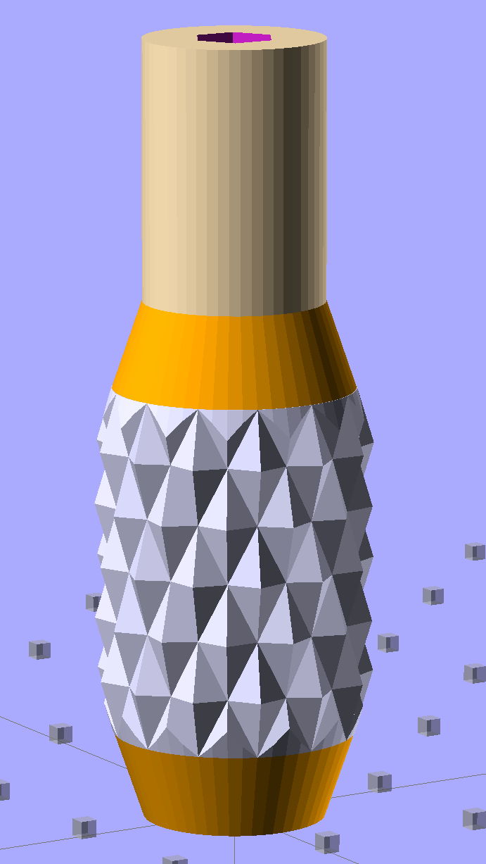
The solid model resembles the illegitimate offspring of a wine bottle and a pineapple:
Sherline Knob – solid model
The knurling comes from aubenc’s Knurled Surface Library v2. I ran off a prototype (on the left), then tweaked the dimensions to get the final version on the right:
Sherline Knobs – knurl depth variation
Being that type of guy, I define the knurl in terms of its diametral pitch, compute the diamond width & length to fit in the available space, then hand those measurements to the knurling library… which recomputes everything and decides on one less diamond than I do: NumSides has a Finagle Constant of -1 to make the answer come out right. We may be using a different diameter or something, but I haven’t deciphered the source code. It’s parametric out the wazoo, as usual, so you can spin up what you like, how you like it.
Anyhow, a 24 DP knurl with 1.0 mm depth looks and feels pretty good; the XY resolution isn’t good enough for a 48 DP knurl around that knob diameter. The diamonds don’t come out as crisp and pointy as crushed steel knurls, but they’re OK for my fingers.
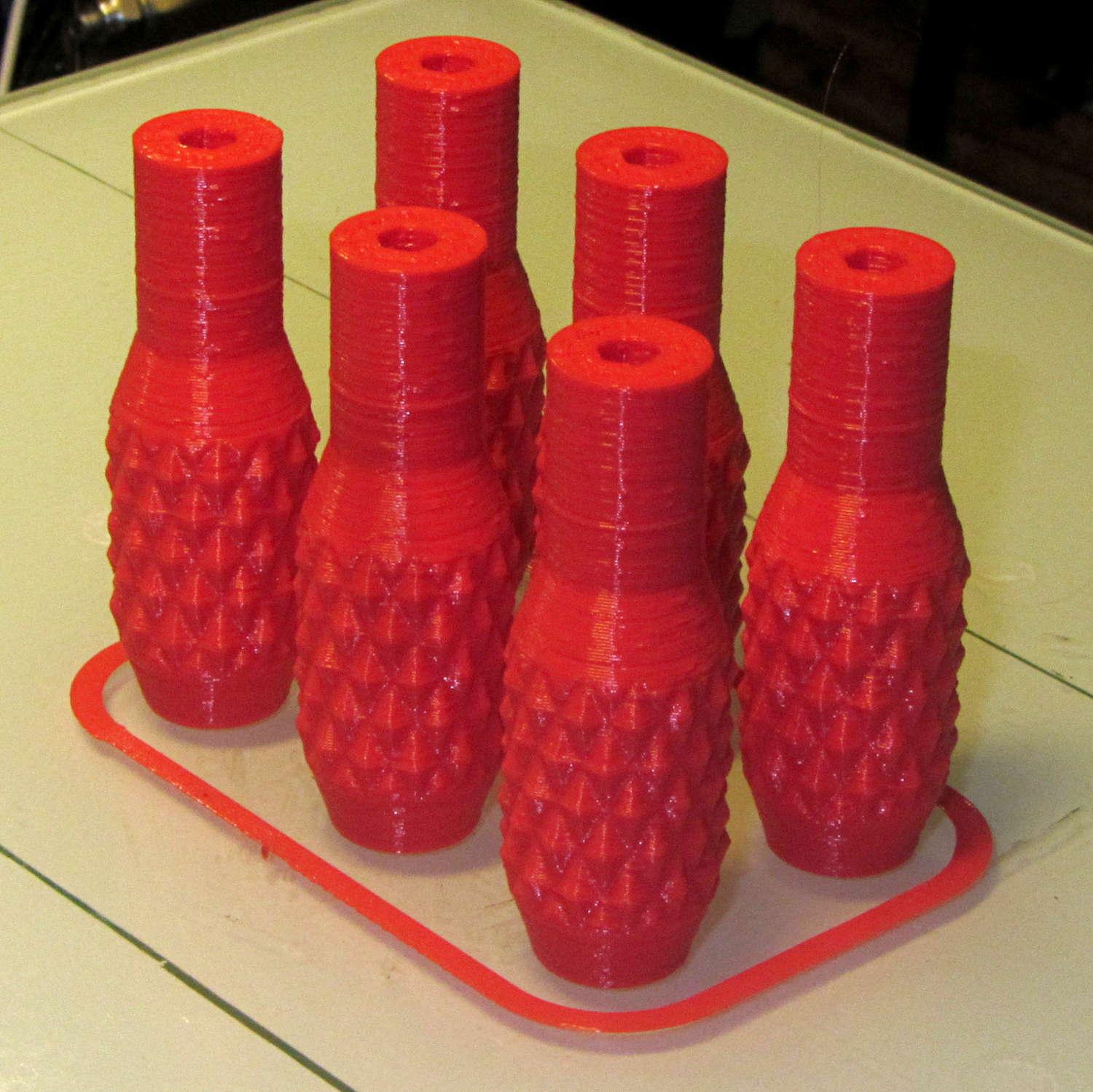
Doing half a dozen doesn’t take much longer than doing a few, because there’s a 20 second minimum layer time in effect and those things don’t have much plastic, so now I have one for the hold-down clamps and another for Show-n-Tell sessions:
Sherline Knobs – M2 platform
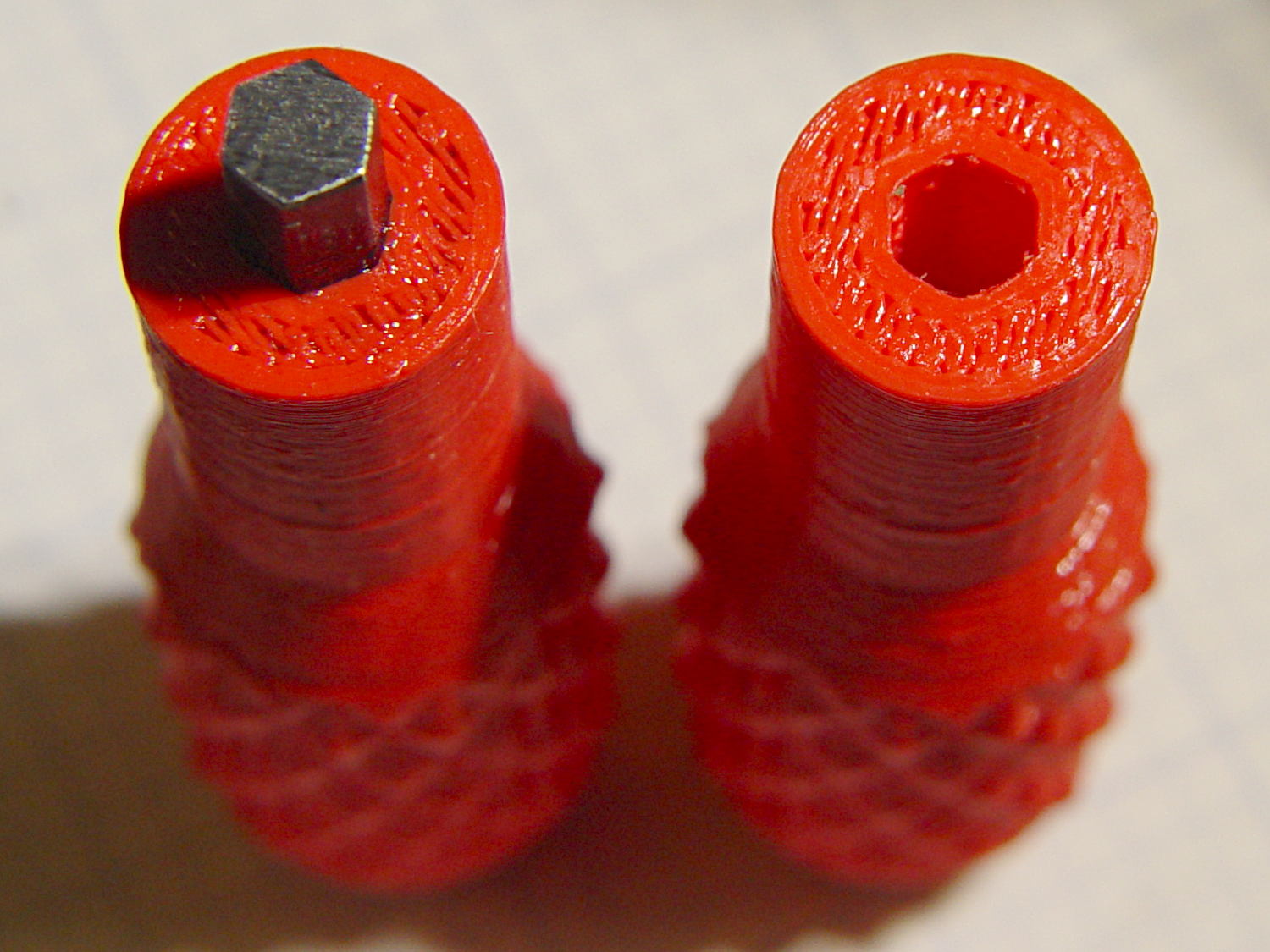
I chopped a 5/32 inch hex key into five 15 mm lengths with a Dremel cutoff wheel, then filed both ends flat and broke the edges. The hex stubs were a press fit in the hex holes, so I finger-started them, grabbed the hex in the drill press, aligned the handle below, and rammed the stub about 5 mm deep. The final depth comes from jamming the wrench into the chuck and pressing firmly, so the stubs project exactly as far as possible:
Sherline Knobs – hex key inserted
One might quibble about the infill on the end; one may go adjust one’s own printer as one prefers.
There’s 0.1 mm more HoleWindage than usual, because these holes must fix a hex shaft, not a circular pin, and the corners need some clearance. They came out a firm press fit: exactly what’s needed.
They’re no good for final tightening of those chuck jaws, but that’s not their purpose…