Ed Nisley's Blog: Shop notes, electronics, firmware, machinery, 3D printing, laser cuttery, and curiosities. Contents: 100% human thinking, 0% AI slop.
For some unknown reason, one of the very rare updates to the Ubuntu 10.04 LTS infrastructure (for LinuxCNC 2.5.3 on my Foxconn D510 box, driving the Sherline mill) stopped supporting the system board’s built-in NIC: networking stopped working. The only symptom was that the NIC didn’t respond and all the usual tricks were unproductive.
After some fruitless searching, I took the easy way out:
NIC added to Foxconn D510 PC
That’s the backside of an ancient NIC using the classic Tulip driver. It used to have a full-size bracket, which I chopped off, bent, and filed to suit, much as with that one in the D525.
Fired it up, the kernel automagically picked the proper driver, and networking Just Worked again.
Used to be, back in the day, that when you got a box full of shiny new electronics, it bore stickers: “Do not accept if seal is broken” or “Factory sealed” or “Genuine product” or something like that. When you slit the seal, you had some confidence that the last person to look in the box sat at the end of their production line; I’ll grant you that counterfeit stickers have become cheap & readily available, but it’s the principle of the thing.
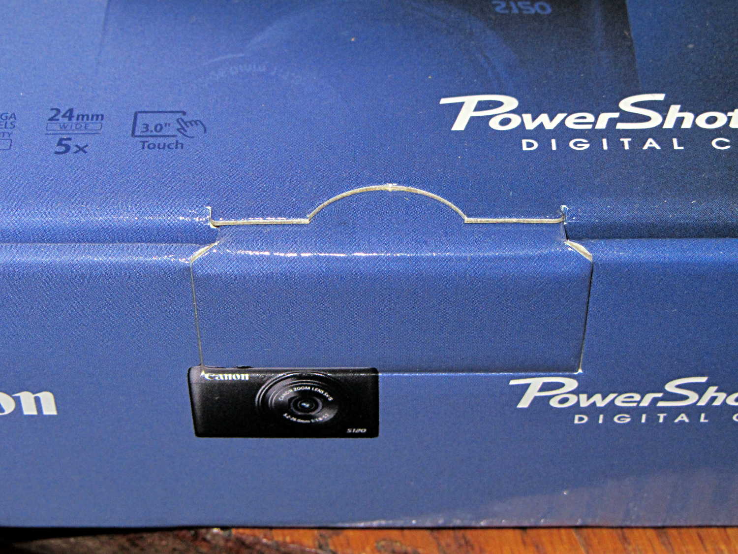
Nowadays, a shiny new Canon camera arrives in a box with a tab tucked into a slit:
Canon Camera box – unopened and unsealed
The box looked unopened and everything inside seemed in order, but … even though I’d seen this before on other cameras, it’s still disconcerting.
A few months ago I fired the Thing-O-Matic, only to have it wake up dead. Not exactly dead, but spitting out checksum errors on simple G-Code files sent from Pronterface, which used to work just fine. Trying a bit of this-and-that to no avail, I proposed to The Mighty Thor that I could loan the carcass to Squidwrench, reanimate it with a less bizarre set of hardware and firmware than the much-hacked Makerbot menagerie under the hood, and use it as an exemplar in my 3D Printing classes.
Fortunately, that particular Thing-O-Matic has the most well-documented hardware evah…
Matt suggested an Azteeg X3 controller, because it has thermocouple inputs that match the existing sensor, Thor ordered one, and I tinkered up a first-pass version of Marlin that could read the inputs and twiddle the motors. The firmware is on Github, not that you’ll need it for anything you’re doing; more on that later.
Here’s the Official Doc for the microstepping jumpers hidden under the driver boards:
Azteeg X3 – microstep jumpers
That’s XYZE = 16 16 8 4, respectively, with a spare slot (and spare driver, not installed) for the second extruder it’ll never have.
The extruder’s Type K thermocouple connects to the TC1 port on the shield, exactly reversed from the way you see the test thermocouple there: the red lead is to the left, the yellow lead is to the right. If you get it backwards, the indicated temperature goes down when you touch the bead. The printer’s thermocouple has some backstory.
The 10 kΩ thermistor bead connects to the BED port on the main board and isn’t polarized. The Heated Build Platform has a bit of backstory, too.
The gutted TOM286 carcass with the MBI hardware off to the side:
TOM286 – gutted electronics bay
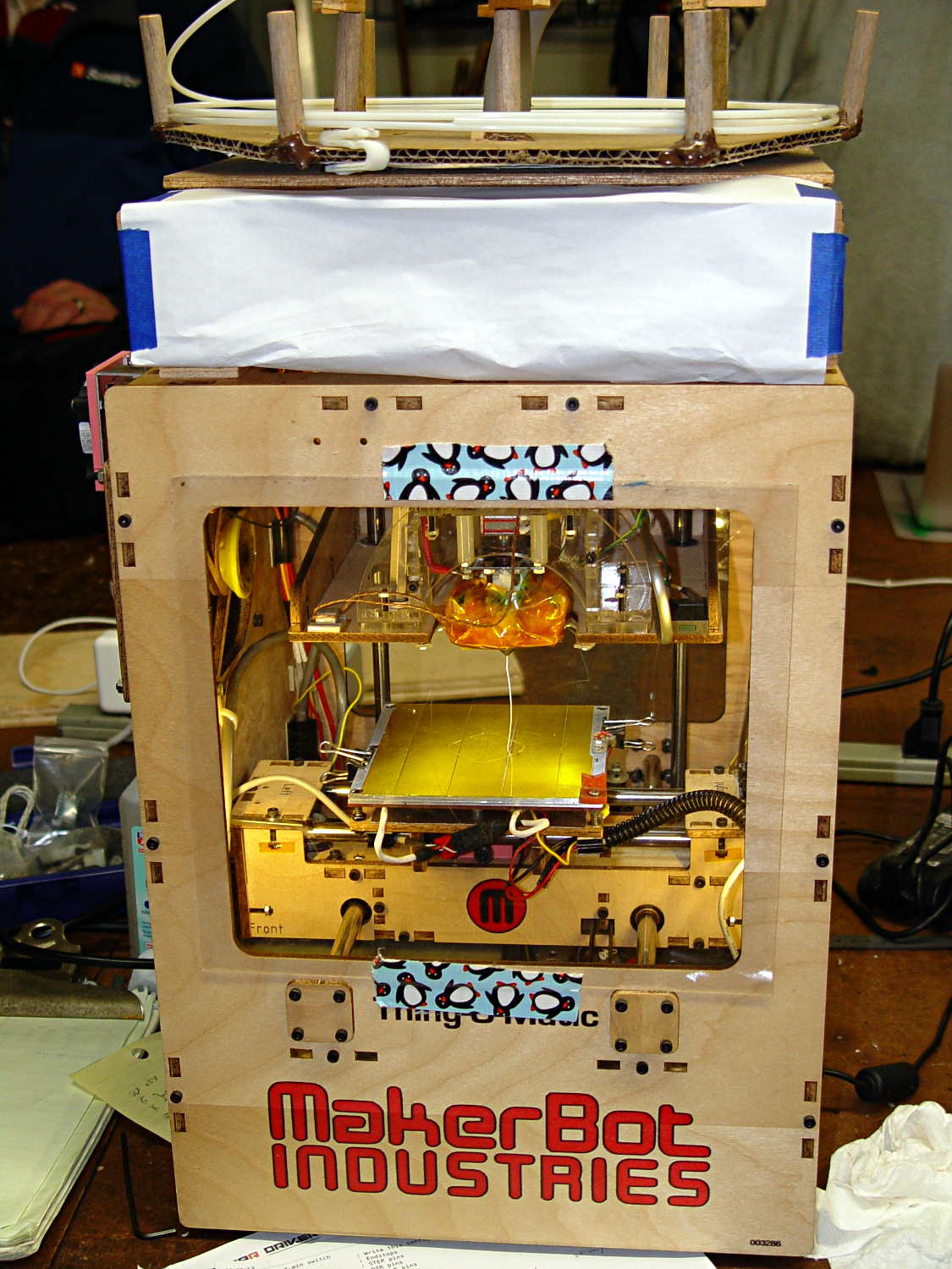
After a few sessions, it looked pretty cheerful again:
This is what you see when looking down through the acrylic baseplate:
Azteeg X3 – inside TOM286
The blurry silver rectangle off to the left is an aluminum channel glommed to bottom of the acrylic baseplate with silicone snot to eliminate a nasty mechanical resonance.
The thermal cutout circuitry isn’t wired in yet; the ATX power supply has its -Power-On pin hotwired to the adjacent ground pin for now. The X3 gets its power directly from the +12 V supply, so there doesn’t seem to be any way to power the X3 from the +5 V Standby ouput, deliver +12 V to the motors, and switch the supply through the X3’s ATX output pin.
The heaters work fine, the motors turn properly, and the extruder feeds molten plastic; all the motor calibrations seem to be pretty close. The first test object was a total botch, of course, but the printer’s parts seem to work OK again.
Mary has been learning free motion quilting, which uses a special sewing-machine foot that holds the fabric in place. Leah Day describes modifying a standard darning foot, but I suggested deploying a bit more shop-fu to do it right. The notion of “adjusting” something with a twisted rubber band just made my skin crawl…
The starting point is a Brewer BP1814 “FOOT Darning/Quilting low shank with clear base”, two of which appear next to an older version that she’s had for quite some time. The rightmost one has my modifications:
Brewer BP1814 Quilting Foot – assortment
The older (mostly metal) foot works much better for its intended purpose, but the newer white plastic version seems easier to modify for free-motion quilting. The older spring is much softer than the new ones, for whatever that’s worth. After the modification, the spring pressure becomes largely irrelevant, as it only acts when something pushes up on the base.
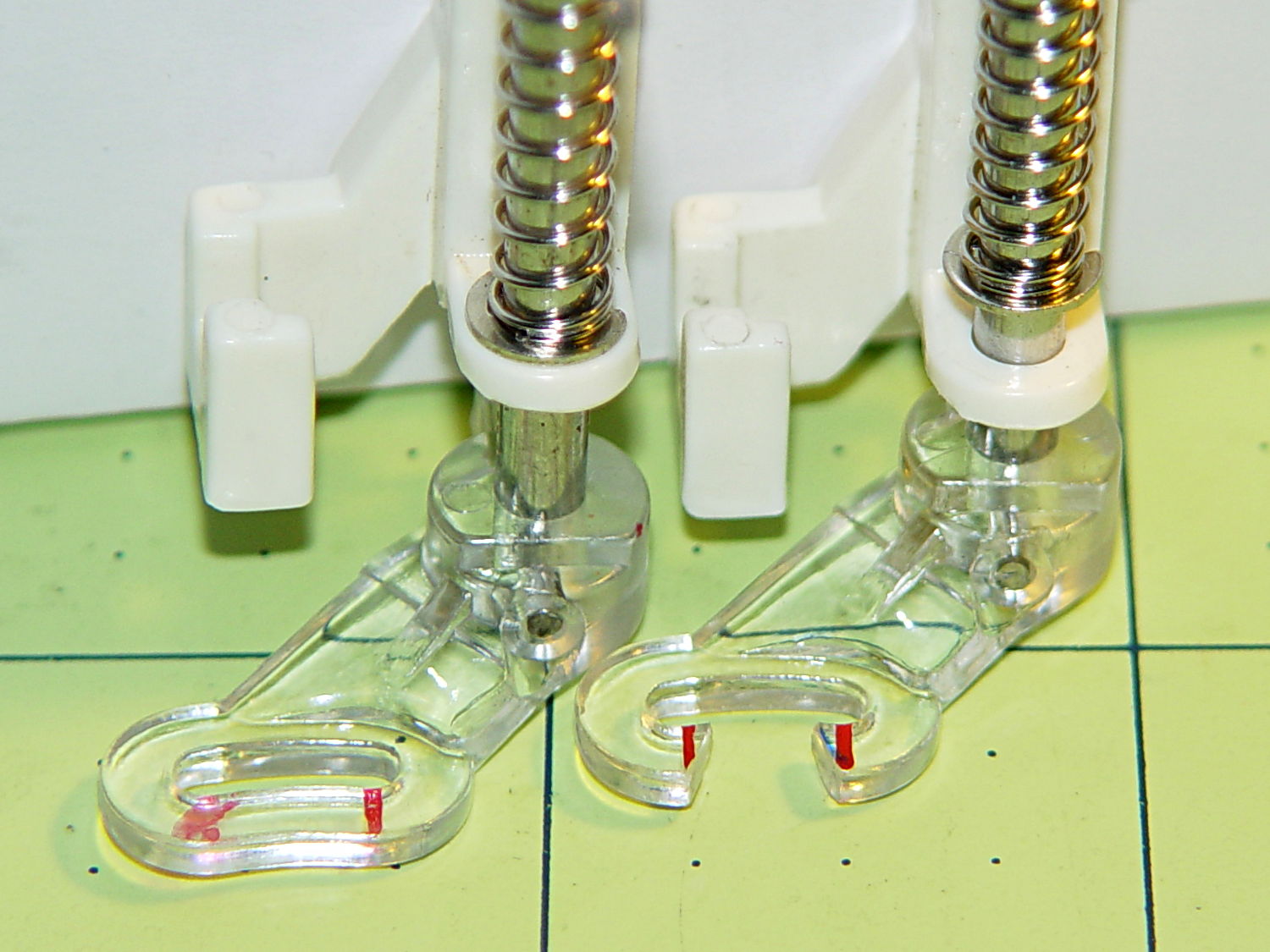
The first modification improves visibility by cutting out part of the transparent plastic base. Leah suggests chopping it with a diagonal cutter (“jewelry clippers”), but I deployed a slitting saw in the Dremel tool at low speed to avoid melting. Mary wanted angled cuts, so that’s what she got:
Modified Darning Foot – opened base
A bit of touchup with a fine file smoothed out the edges so the base slides easily over the fabric. There’s no way to remove the red guide lines; the un-modified foot on the left emerged from its bag with that smeared line.
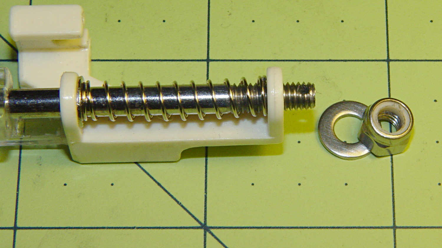
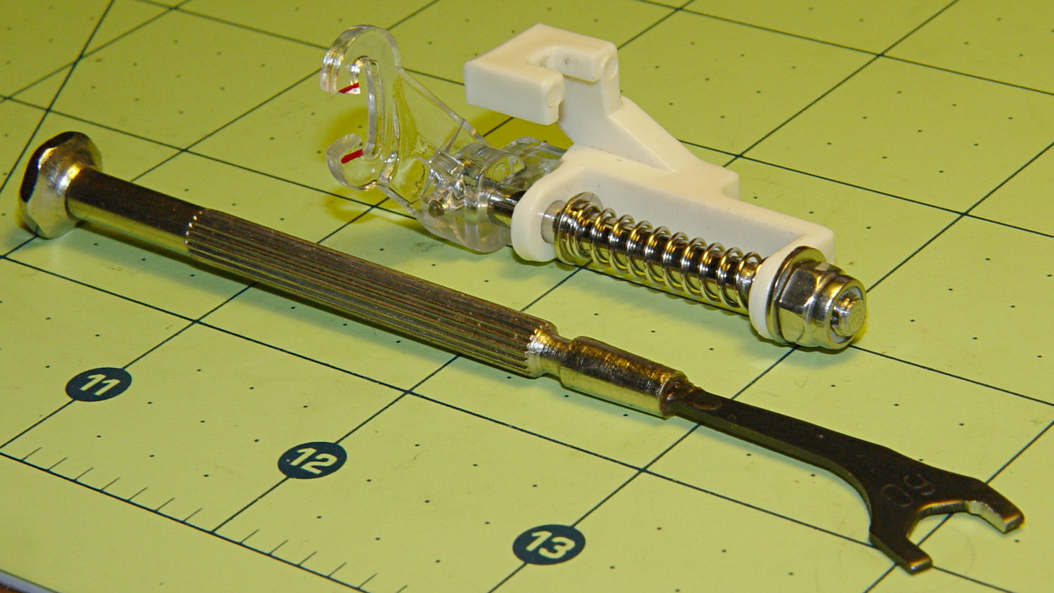
Then drive out the top metal pin with a small drift punch, hold the base and shaft, remove the C-clip, capture the spring, and extract the base and shaft. The 4.0 mm diameter metal shaft cries out to be threaded, so that’s what I did; this picture shows the reassembled shaft and spring:
Modified Darning Foot – threaded shaft
That’s significantly harder to accomplish than it looks, because there’s no practical way to remove the plastic base (it’s pinned in place, but one side of the cross-hole is blocked). I filed the end of the shaft to a taper that started the M4.0x0.7 die a bit more easily, clamped the shaft in the bench vise, applied nasty sulfur-based tapping fluid, crossed my fingers and eyes, held my nose, and managed to make it happen without cracking the plastic.
I reamed out the Nyloc nut with a hand-twisted series of drills, through about #24 = 3.861 mm, to reduce the locking torque. It’s now just slightly more than finger-tight, which should suffice.
In use, the foot fits under the sewing machine’s arm and puts the nut where fingers can’t reach. I filed a 6.0 mm “precision wrench” to fit the 6.8 mm nut flats and it’s All Good:
Modified Darning Foot – assembled with wrench
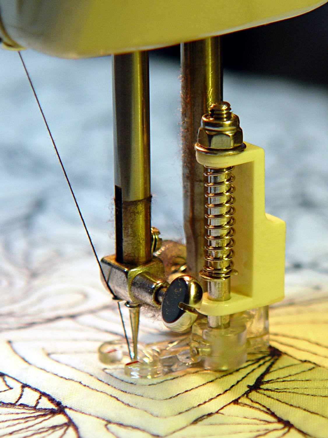
A staged photo op atop some trial quilting:
Modified Darning Foot – in action
With a Nyloc nut instead of a rubber band, it will stay exactly where she wants it…
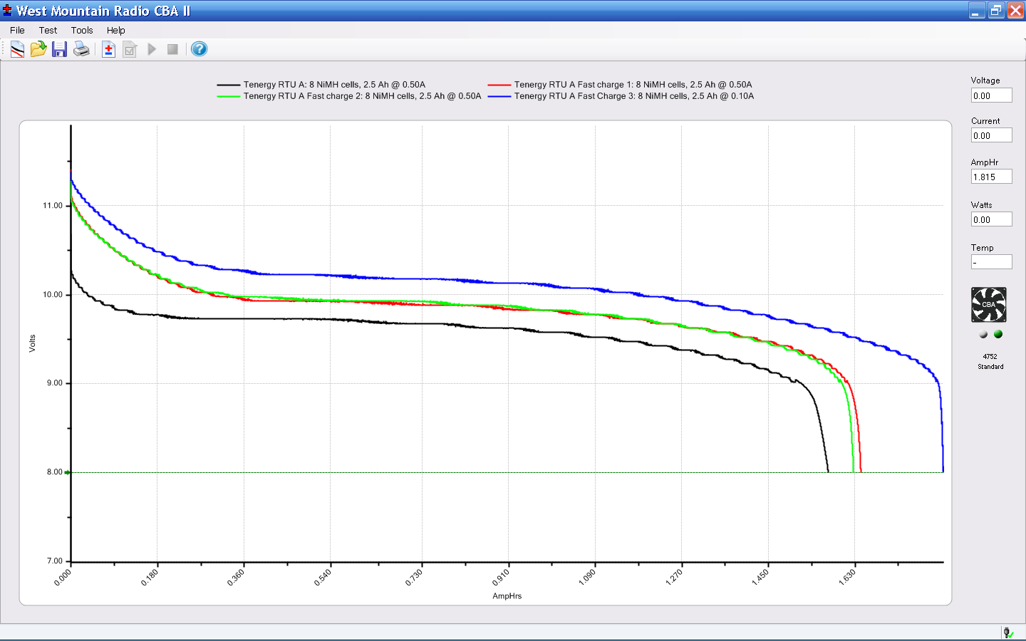
The main reason for taking the FC1002 frequency counter apart was to replace the failed quad-AA NiCd battery pack. Rather than buy new cells with tabs, I recycled some low-discharge “ready to use” NiMH cells from the heap. Back in 2009, they looked like this:
Tenergy RTU Pack A Tests – Aug 2009
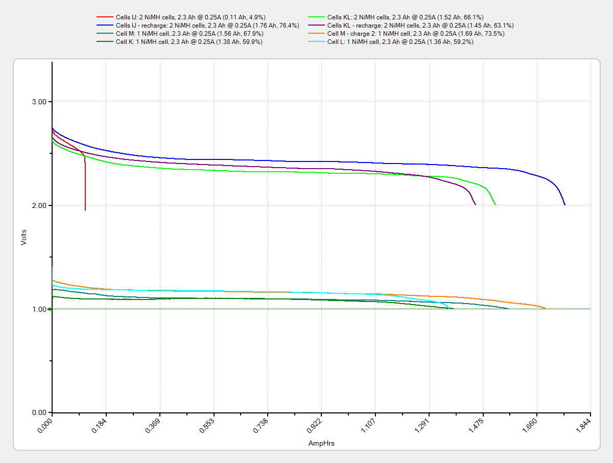
Nowadays, they’re a bit less peppy:
Tenergy RTU – 2014-01 – loose cells
The red blooper shows that you can’t trust a smart fast charger to get the right answer; it concluded that pair was fully charged. After the discharge test and an overnight C/10 charge, they regained as much enthusiasm as they’ll ever have.
They have slightly less capacity than in 2009 and also a somewhat lower terminal voltage. That shouldn’t matter here, as the frequency meter has a power supply to take care of that problem.
Although I’ve sometimes been able to (quickly!) solder directly to ordinary AA cells, a trial run on a defunct RTU cell showed that wasn’t going to work on whatever variety of steel they used, no matter how much I scuffed it and despite using aggressive flux that normally blends silver solder onto stainless steel.
Fortunately, the top half of a four cell case fit exactly in the space available, so I used woven copper fabric tape inside the case to interconnect the cells, then lashed everything together with the obligatory Kapton tape:
FC1002 Frequency Counter – battery pack
That cracked faceplate isn’t the nicest thing to confront, but it’ll suffice until I get more motivation:
And it came to pass in the Christmas Season that our ignition keys began jamming in the lock, rather than just starting the van. It seems Toyota used split wafers in their locks up through the early part of this millennium, with the result that the delicate wafer edges tend to wear out both themselves and the edges of the keys.
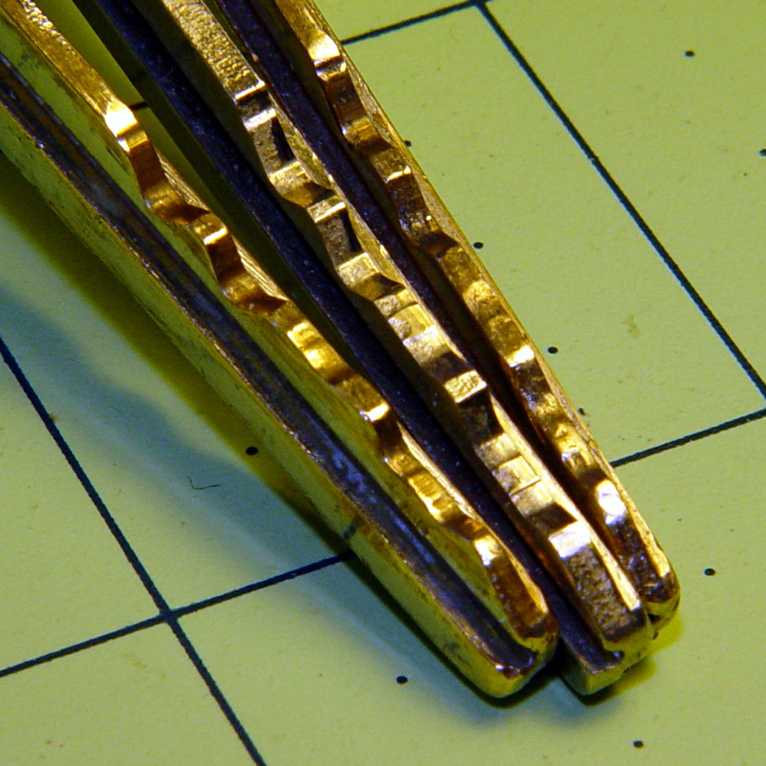
I can’t vouch for the wafers, but the keys definitely aren’t in good shape:
Ignition keys – worn vs new
Given that picture, someone can probably conjure up a shiny new key and drive away with our 14-year-old Sienna van. It just rolled over 90 k miles and is in pretty good condition. New battery and hood prop pivot, too.
Being that type of guy, the first thing I did with the new van was to get duplicate keys and drop the OEM keys into the “2000 Sienna” file folder. The middle key in that photo has had maybe a dozen uses and is in pristine condition.
Rumor has it that one can cannibalize a set of split wafers from the glove box lock:
Glove box latch
Or, according to different sources, you can simply discard the split wafers and be done with it.
The trick to removing the lock cylinder lies in turning the key to the Accessory position, then poking a pointy object into a small hole to depress an internal spring-loaded pin. Of course, one must disable the air bags, dismantle the steering wheel, and remove half a dozen trim panels to reveal the small hole.
Fortunately, the two “new” keys from the file folder work perfectly and we’ll run with them for a while. I suppose I should get another set of duplicates, but …