I loves me some good error message:
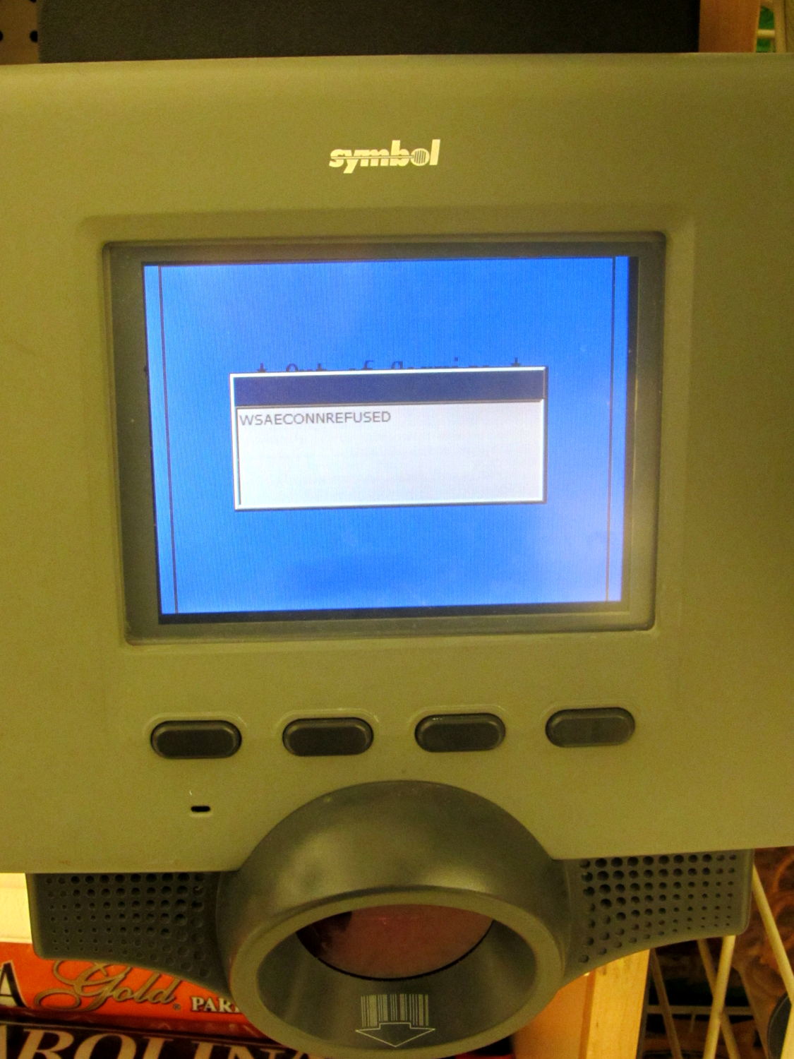
A closer look:
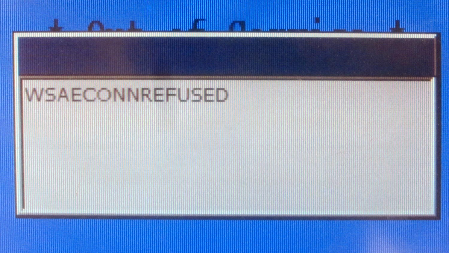
If the popup appeared just one pixel lower, you could easily decode the message behind it; perhaps * Out of Service * fits?
At least it doesn’t show an OK? button.
The Smell of Molten Projects in the Morning
Ed Nisley's Blog: Shop notes, electronics, firmware, machinery, 3D printing, laser cuttery, and curiosities. Contents: 100% human thinking, 0% AI slop.
I loves me some good error message:
A closer look:
If the popup appeared just one pixel lower, you could easily decode the message behind it; perhaps * Out of Service * fits?
At least it doesn’t show an OK? button.
Back in the day, the Hudson River would freeze solid enough to supply all the icehouses in the valley that stored a year’s worth of refrigeration. These days, it’s probably a good thing we don’t depend on river ice, because it’s not nearly frozen in mid-January:

That’s Roth Hall at the CIA over on the left, with a Dutchess County Water and Wastewater Authority water tower on St. Andrews Road, about a mile beyond it.
The barge looks like it’s deadheading back to NYC after unloading, most likely at the Port of Albany, following the clear channel bulldozed by an earlier and much larger barge.
Start with a monochrome image:

A bit of tinkering produce a height map image:

I picked a 3.0 pixel/mm scale factor, so a 33 mm mold covers only 100 pixels. That image is 1100 mm tall and will be reduced by a factor of 10 to the final image size: this is not the place for fine detail and fancy lettering!
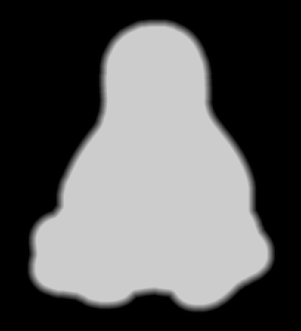
The conversion process assumes you’ll handle the Z axis scaling yourself, so the script no longer normalizes the gray levels. If you select gray levels using HSV, the V slider gives you a direct reading in percent-of-maximum thickness; Tux varies from V = 80 to 100, so he’s pretty much bas relief.
The border around the image must be 0 = black and will be stripped from the final mold. That’s why Tux doesn’t turn into a bird served on a rectangular platter.
Because this is a mold, its edges must have some draft, which means the outline must shade from black to whatever gray represents the interior of the mold. Do this:
Which looks like this with V=80 gray inside:
The 30 pixel feathered border, scaled by the 10× reduction, means the edge of the mold goes from 0 = black to the interior in about 3 pixel / (3 pixel/mm) = 1 mm. If the interior is 255 = white at 7 mm, the draft angle is arctan 1/7 = 8°, which is probably about right for the deepest part of the mold. The edge of the Tux mold is V = 80 (or about 200 gray), so it’s at 0.8 × 7 mm = 5.6 mm and the draft angle is arctan 1/5.6 = 10°.
Inside the mold, anything goes, but you should avoid 0 = black levels so that the alignment pins don’t poke through the mold. Any 255 = 100 V = white levels will be the maximum mold thickness, which is 7 mm for the molds you see here and that may be somewhat too thick for a chocolate treat. It is really hard to maintain draft on small features, but I think if you don’t get carried away it’ll be all good.
There’s also a 1 mm backing plate below the mold that ensures the deepest mold parts have some substance behind them and the alignment pin sockets have enough depth to be useful.
Scaling the image down by 10× to about 110 pixels tall (including the black border) will make the final Tux mold about 37 mm tall:

This image enlarges it by 10× with no smoothing to show the gritty nature of the image. This is why you can’t have delicate detail or fine lettering:

Notice the nearly complete lack of draft on the interior features. Each level differs by about V = 5 over the range V = 80(the border) to V = 100 (beak and flipper), so they amount to only 0.05 × 7 mm = 0.35 mm = one or two thread layers at 0.20 mm/layer. I think if you were doing this right, you’d pick an overall thickness so that V = 5 increments corresponded to one layer or use whatever V increments corresponded to a single layer.
Running that image through the Bash script & OpenSCAD programs (more on those later) produces a reasonable result:

When it’s converted into plastic, you can count the layers in each V = 5 level (clicky for more dots):
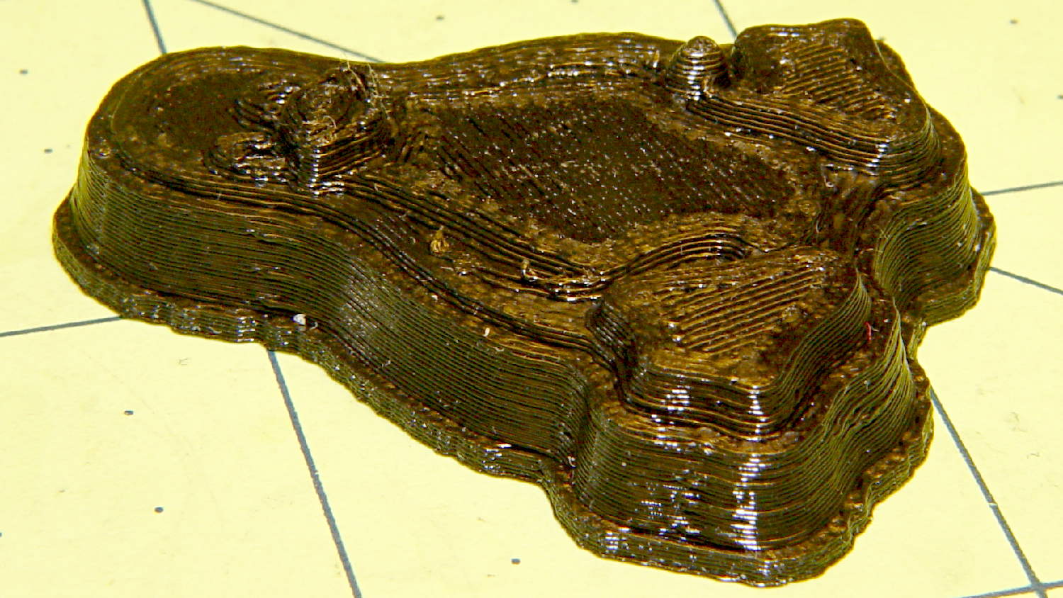
It may be a bit less rounded in the tummy than the real Tux, but seems good enough for the purpose.
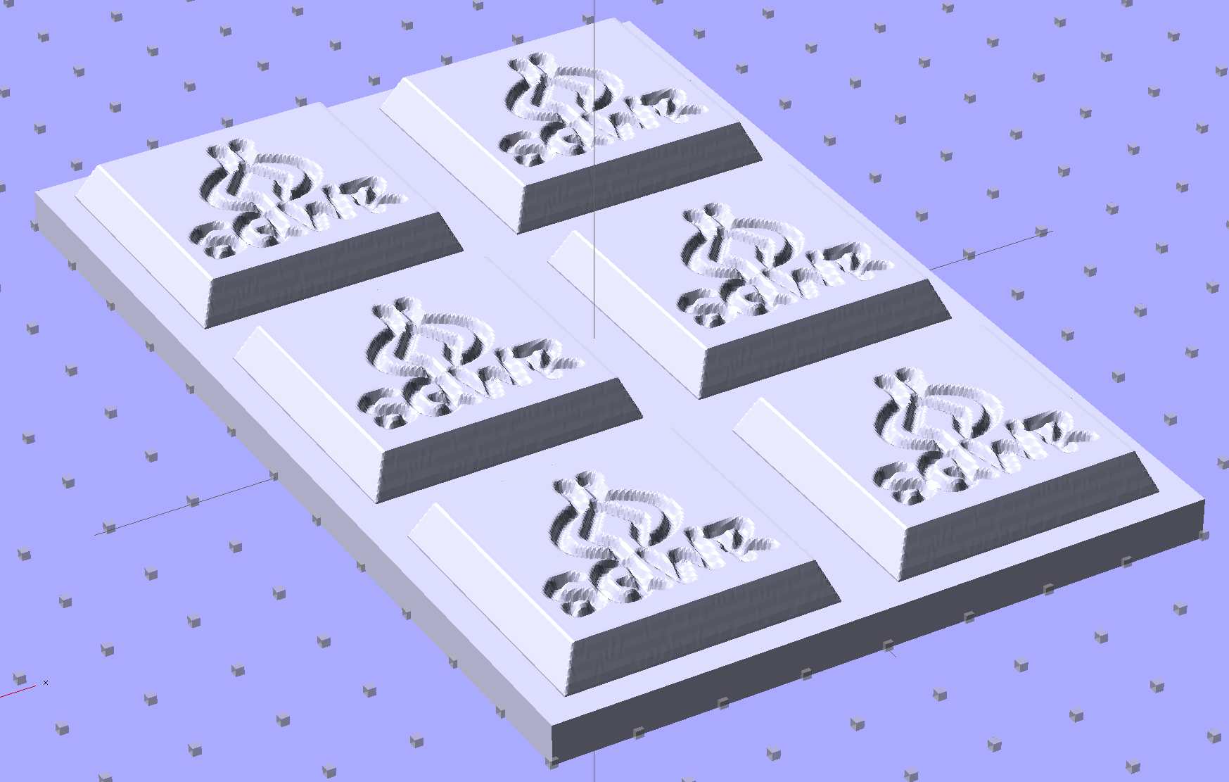
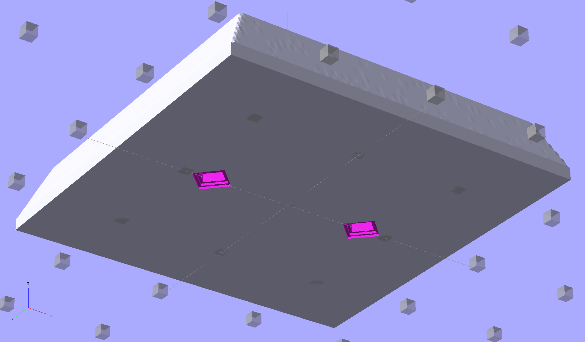
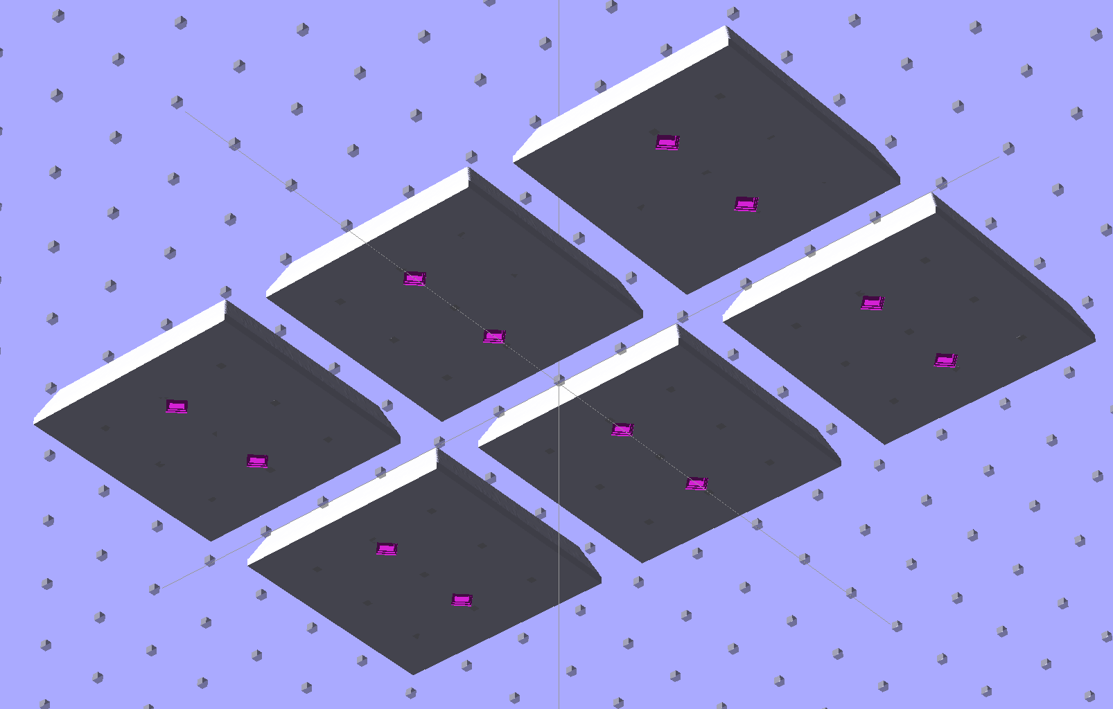
Given an STL file generated from a height map image, import it into OpenSCAD:
Then slide a plate under six copies to produce a positive model for a casting mold:
This is one of the few cases where the compiled-and-rendered version looks better, as though you’d shrink-wrapped it in gold foil:
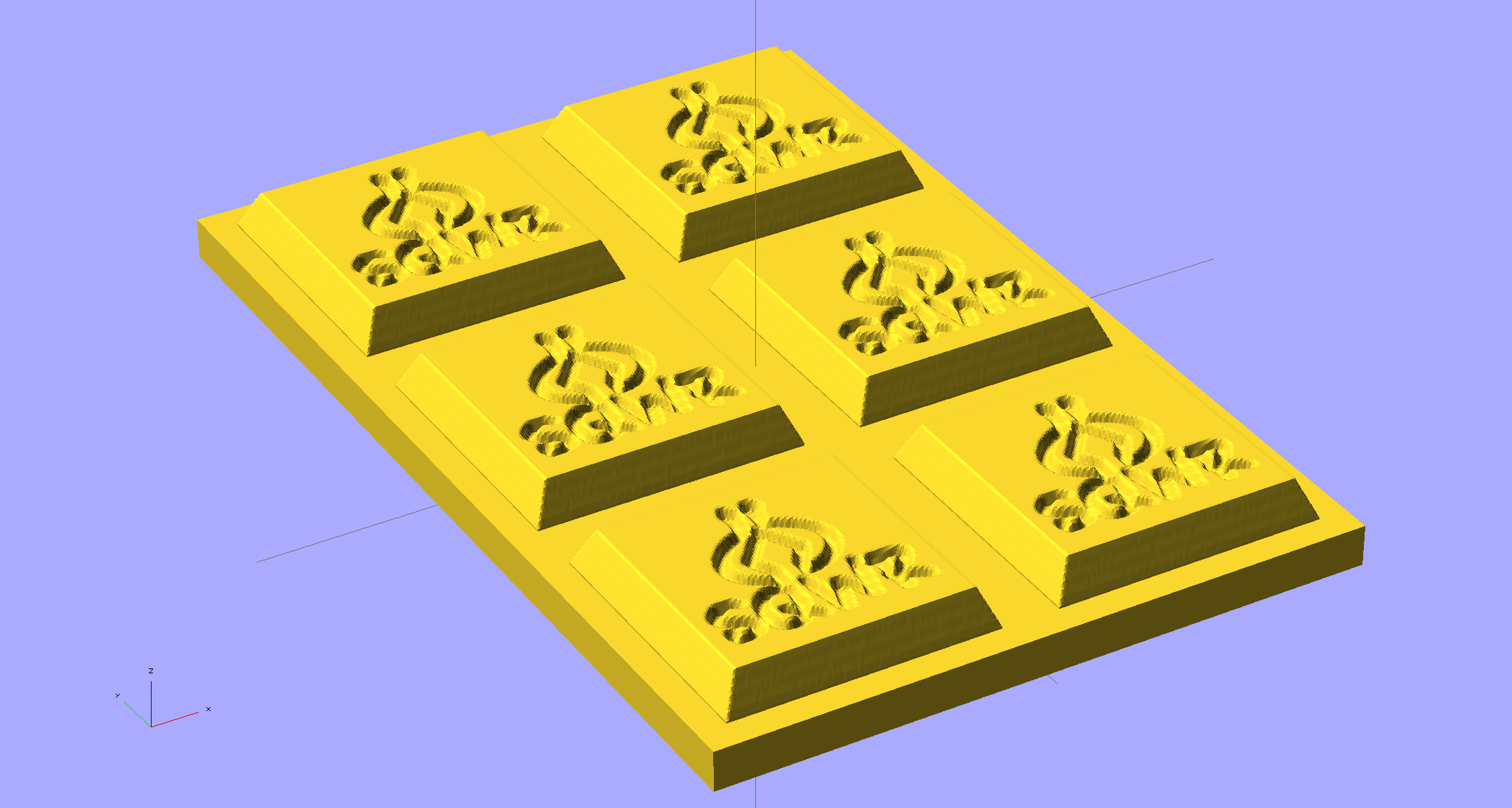
The height map STLs each have a bazillion tiny facets that take forever-and-a-day (well, the better part of half an hour for this set) to render, not to mention that the whole array would take two hours to print… and then be used once or twice to produce the flexy silicone negative mold.
So it’s better to have a generic frame with alignment pin holes that you print once:
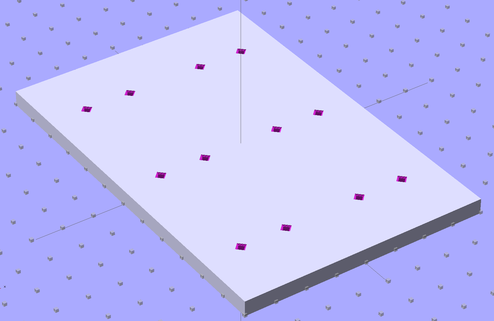
Better yet, just CNC-drill those holes in a nice, flat acrylic / polycarbonate slab.
Insert and glue filament snippets as alignment pins, trim about 1 mm over the surface to fit the small molds.
The OpenSCAD program can punch matching holes in the back of the small mold:
Or you could print out an array of the things with holes:
It’s not clear having OpenSCAD labor for half an hour to generate and emit a single STL file spanning all six molds is a win. Given that you don’t care about the mold-to-mold spacing, having Slic3r duplicate the same small STL file half a dozen (or more!) times would probably be a net win.
There’s no reason the OpenSCAD program that creates the original STL from the height map image can’t punch alignment pin holes, too, which would avoid this import-and-recompile step. If you’re going with a CNC-drilled plate, then it would make even more sense to not have a pair of OpenSCAD programs.
Anyhow.
Apply a handful of small molds to the backing plate with tapeless sticky, butter it up with mold release agent, slather on silicone putty, flip it over to produce a smooth surface “under” the small molds (so you can rest it flat on a table when pouring molten chocolate into the cavities), cure, peel, and you’d get a pretty good negative mold.
This may not make any practical sense, but it was easy & fun to see what’s possible…
The OpenSCAD source code:
// Positive mold framework for chocolate slabs
// Ed Nisley - KE4ZNU - January 2014

Layout = "FramePins";		// Molds FramePins FrameMolds Frame Single Pin

//- Extrusion parameters must match reality!
//  Print with 2 shells and 3 solid layers

ThreadThick = 0.20;
ThreadWidth = 0.40;

Protrusion = 0.1;			// make holes end cleanly

HoleWindage = 0.2;

//----------------------
// Dimensions

FileName = "SqWr-press.stl";	// overrride with -D

Molds = [2,3];					// count of molds within framework

MoldOC = [40.0,40.0];			// on-center spacing of molds
MoldSlab = 1.0;					// thickness of slab under molds

BaseThick = 5.0;

BaseSize = [(Molds[0]*MoldOC[0] + 0),(Molds[1]*MoldOC[1] + 0),BaseThick];
echo(str("Overall base: ",BaseSize));

PinOD = 1.75;					// locating pin diameter
PinLength = 2.0;				//  ... total length
PinSpace = 15.0;				// spacing within mold item

//----------------------
// Useful routines

//- Put peg grid on build surface

module ShowPegGrid(Space = 10.0,Size = 1.0) {

	RangeX = floor(100 / Space);
	RangeY = floor(125 / Space);

	for (x=[-RangeX:RangeX])
		for (y=[-RangeY:RangeY])
			translate([x*Space,y*Space,Size/2])
			%cube(Size,center=true);

}

module PolyCyl(Dia,Height,ForceSides=0) {			// based on nophead's polyholes

  Sides = (ForceSides != 0) ? ForceSides : (ceil(Dia) + 2);

  FixDia = Dia / cos(180/Sides);

  cylinder(r=(FixDia + HoleWindage)/2,
           h=Height,
	   $fn=Sides);
}

// Locating pin hole with glue recess
//  Default length is two pin diameters on each side of the split

module LocatingPin(Dia=PinOD,Len=0.0) {

	PinLen = (Len != 0.0) ? Len : (4*Dia);

	translate([0,0,-ThreadThick])
		PolyCyl((Dia + 2*ThreadWidth),2*ThreadThick,4);

	translate([0,0,-2*ThreadThick])
		PolyCyl((Dia + 1*ThreadWidth),4*ThreadThick,4);

	translate([0,0,-(Len/2 + ThreadThick)])
		PolyCyl(Dia,(Len + 2*ThreadThick),4);

}

module LocatingPins(Length) {
	for (i=[-1,1])
	translate([i*PinSpace/2,0,0])
		LocatingPin(Len=Length);
}

//-- import a single mold item

module MoldItem() {
	import(FileName,convexity=10);
}

//-- Overall frame shape

module Frame() {

	translate([0,0,BaseSize[2]/2])		// platform under molds
		cube(BaseSize,center=true);

}

//- Build it

ShowPegGrid();

if (Layout == "Pin")
	LocatingPin(Len=PinLength);

if (Layout == "Single")
	difference() {
		MoldItem();
		LocatingPins(PinLength);
	}

if (Layout == "Frame")
	Frame();

if (Layout == "Molds") {
	translate([-MoldOC[0]*(Molds[0] - 1)/2,-MoldOC[1]*(Molds[1] - 1)/2,0])
	for (i=[0:Molds[0]-1],j=[0:Molds[1]-1])
		translate([i*MoldOC[0],j*MoldOC[1],0])
			difference() {
				MoldItem();
				LocatingPins(PinLength);
			}
}

if (Layout == "FramePins")
	difference() {
		Frame();

		translate([-MoldOC[0]*(Molds[0] - 1)/2,-MoldOC[1]*(Molds[1] - 1)/2,0])
			for (i=[0:Molds[0]-1],j=[0:Molds[1]-1])
				translate([i*MoldOC[0],j*MoldOC[1],BaseSize[2]])
					LocatingPins(BaseThick);
	}

if (Layout == "FrameMolds") {
	Frame();
	translate([-MoldOC[0]*(Molds[0] - 1)/2,-MoldOC[1]*(Molds[1] - 1)/2,0])
		for (i=[0:Molds[0]-1],j=[0:Molds[1]-1])
			translate([i*MoldOC[0],j*MoldOC[1],BaseThick - MoldSlab + Protrusion])
			MoldItem();
}
Given that you really don’t care about the absolute dimensions, you can generate a positive mold from a height map image and avoid the entire solid modeling process. Having already solved the cookie press problem, this was a quick-and-easy feasibility study…
Start by selecting the logo, growing the selection by a few pixels, and feathering the edges to produce the mold draft. Then apply a square gradient behind the Squidwrench logo to produce the height map for the edge of the mold. This one is scaled at 3.0 pixel/mm and is 100×100 pixel, thus producing a 33 mm square mold:

One could, of course, produce a non-square mold with a different gradient outline shape.
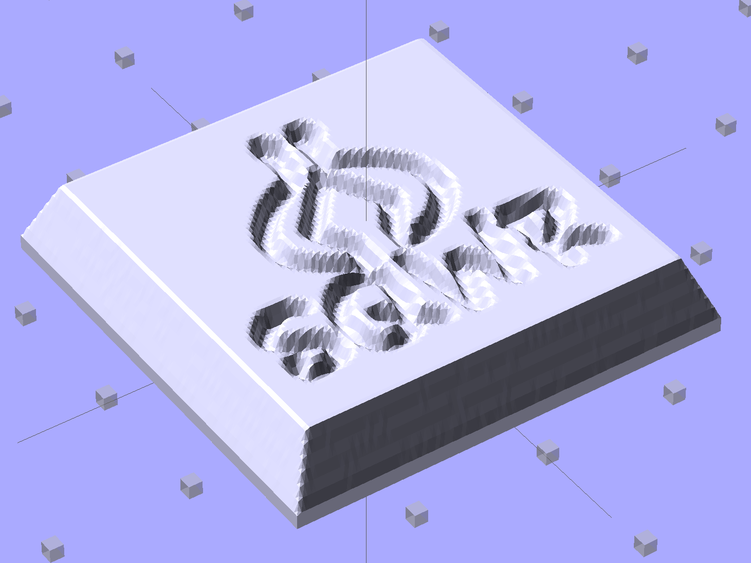
Hand the image to a slightly modified version of the cookie press script (see below) to get an STL file of the mold:

Feed the STL into Slic3r, hand the G-Code to Pronterface, fire the M2!, and you get a positive mold that looks enough like black chocolate to seem ready-to-eat:

I have no idea whether that will work as a mold, but I suspect flexy silicone putty won’t reproduce much of the fine plastic filament detail, so the negative mold won’t grab the chocolate. The logo is six threads deep with a little bit of draft, if that makes any difference.
The backing plate is 1 mm thick and the height map is 5 mm stacked atop that. A few iterations suggested using about 0.75 gray for the logo; working backwards says 5 mm = 25 layers @ 0.20 mm/layer, so a depth of 0.25 * 25 is about six threads.
For production use, I’d be tempted to import maybe a dozen copies of the STL into OpenSCAD, mount them on a platform with a gutter and a lip on the outside, and then print the whole positive multi-cavity mold in one shot.
The Bash script that produces the mold strongly resembles my cookie cutter script and contains about as much cruft as you’d expect. Because we need a positive mold, not a negative press, the script doesn’t invert the colors or flop the image left-to-right, nor does it generate the cookie cutter STL around the outside of the press:
#!/bin/bash
DotsPerMM=3.0
MapHeight=7
ImageName="${1%%.*}"
rm ${ImageName}_* ${ImageName}-press.stl ${ImageName}-cutter.stl
echo Normalize and prepare grayscale image...
convert $1 -type Grayscale -depth 8 -auto-level -trim +repage -flip +set comment ${ImageName}_prep.png
echo Create PGM files...
convert ${ImageName}_prep.png -compress none ${ImageName}_map.pgm
convert ${ImageName}_prep.png -white-threshold 1 -compress none ${ImageName}_plate.pgm
echo Create height map data files...
ImageX=`identify -format '%[fx:w]' ${ImageName}_map.pgm`
ImageY=`identify -format '%[fx:h]' ${ImageName}_map.pgm`
echo Width: ${ImageX} x Height: ${ImageY}
cat ${ImageName}_map.pgm   | tr -s ' \012' '\012' | tail -n +5 | column -x -c $((8*$ImageX)) > ${ImageName}_map.dat
cat ${ImageName}_plate.pgm | tr -s ' \012' '\012' | tail -n +5 | column -x -c $((8*$ImageX)) > ${ImageName}_plate.dat
echo Create cookie press...
time openscad -D BuildPress=true \
-D fnPlate=\"${ImageName}_plate.dat\" \
-D fnMap=\"${ImageName}_map.dat\" -D Height=$MapHeight \
-D ImageX=$ImageX -D ImageY=$ImageY -D DotsPerMM=$DotsPerMM \
-o ${ImageName}-press.stl Cookie\ Cutter.scad
The OpenSCAD program are unchanged from the cookie cutter process.
With this NP-BX1 battery test fixture in hand:

The discharge tests run at 250 mA, which is probably a bit low, as the HDR-AS30V camera can capture video for about two hours on a single battery. Given the Sony’s nominal 1.24 A·h (love that precision!) capacity and derating the Wasabi’s ambitious 1.6 A·h, two hours suggests a current around 500 mA would be more appropriate, but we’ll go with a lower current for now.
Oddly, the two Wasabi batteries (green & blue traces) outperform the Sony OEM battery (red and purple) in terms of voltage:

I can’t explain the small kink just before the big dropoff for both Wasabi batteries. Perhaps the protection circuitry behind the battery terminals has a slight peculiarity?
Looking at the total energy delivered, however:
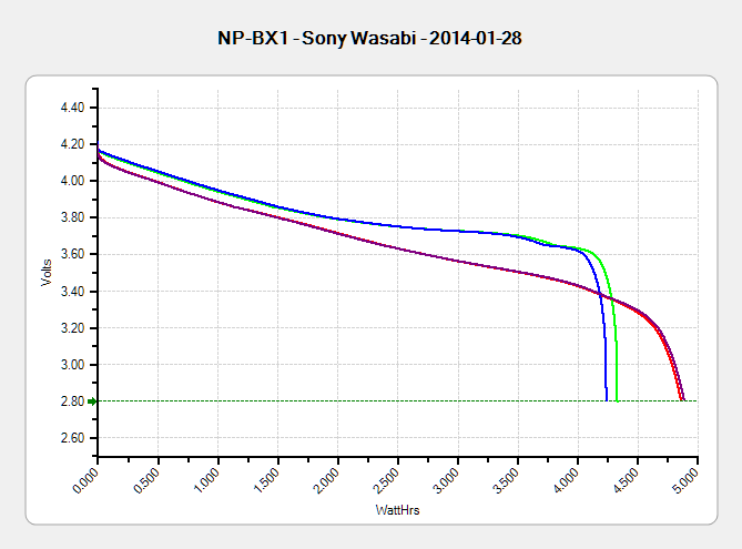
The Sony battery says it’ll deliver 4.5 W·h and actually produces 4.8 W·h. The Wasabi batteries claim 5.7 W·h and don’t even come close at 4.25 W·h.
I cross-checked those results by importing the CSV data into a spreadsheet, computing the point-by-point power, finding the average, and then multiplying by the total test time in hours. Doing it a couple different ways says you can eyeball a reasonable value by multiplying the median voltage by the test current to get average wattage, then multiplying by the total test time to get W·h. That’s within a few percent, which is good enough for me.
The camera’s power supply undoubtedly has a low-voltage cutoff, but it’s a single-cell battery and they might just run it down around 2.8 V; in that case, the Sony batteries will last longer. If the voltage cutout is 3.5 V, similar to the Canon camera, then the Wasabi batteries win.
I don’t have enough experience with the camera or the batteries to predict anything based on actual use.
The price for this specialized wrench used to extract oxygen sensors took a big jump some time after I added a link to it:

Were it not for the very specific part number that’s certainly not available anywhere else, you could take advantage of their “Guaranteed Lowest Prices” to make a quick $494.
As my buddy dBm puts it: “Such a deal!”
