Ed Nisley's Blog: Shop notes, electronics, firmware, machinery, 3D printing, laser cuttery, and curiosities. Contents: 100% human thinking, 0% AI slop.
Coming out of Adams, we’re ready to make a left turn onto Rt 44:
Left turn on red – 2014-07-24
He was one car back in the left-turn storage lane when his light went yellow-to-red, crossed the stop line on the red, and was one car length over the stop line and accelerating when our light changed to green.
We’re ready to start rolling on green, but we’ve learned to wait a few heartbeats for just such occasions; what counts as a fender-bender for you would be a fatality for us.
Y’know how motorists get very, very angry at cyclists? I’ve always wondered why they don’t get that angry when motorists do those same stupid things, at higher speeds with much more energy.
We ride as though we’re thin cars, which is how it’s supposed to be done, and generally don’t get too much hassle.
One thing that is annoying, though: short-stroke yellow cycles that last maybe two seconds. We can cross the stop line on green, accelerating firmly through the intersection, and still get caught in the middle as the signal changes to green-to-yellow-to-red behind us and red-to-green for opposing traffic. No, we didn’t run the yellow, but that’s what it looks like.
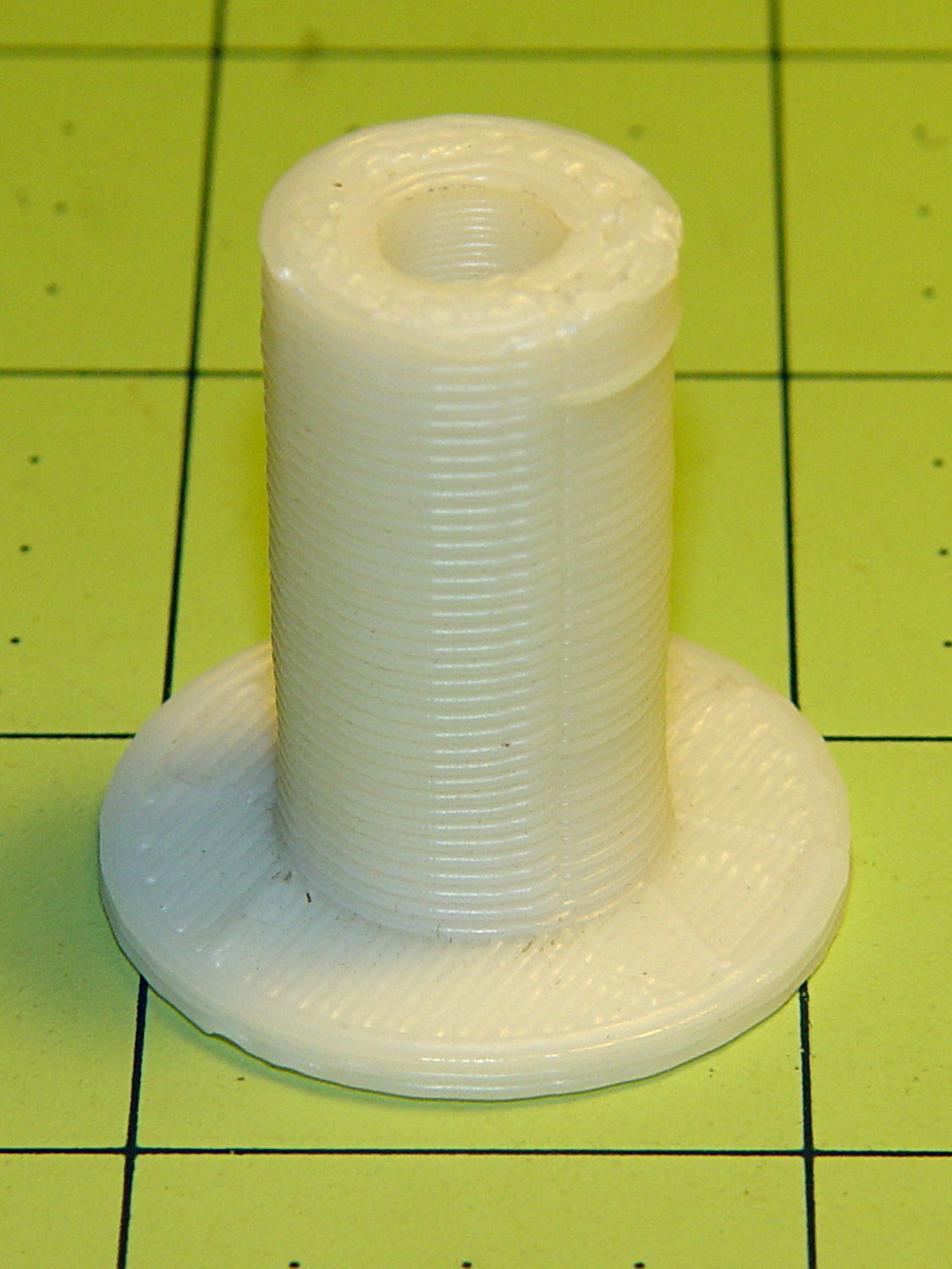
Mary recently learned that large spools of thread have a cross-wound lay that should feed over the end, not from the side as do ordinary stack-wound spools. So I built a right-angle adapter that fits over the not-quite-vertical spool pin on the sewing machine and aims directly at the thread tensioner:
Large spool adapter – on sewing machine
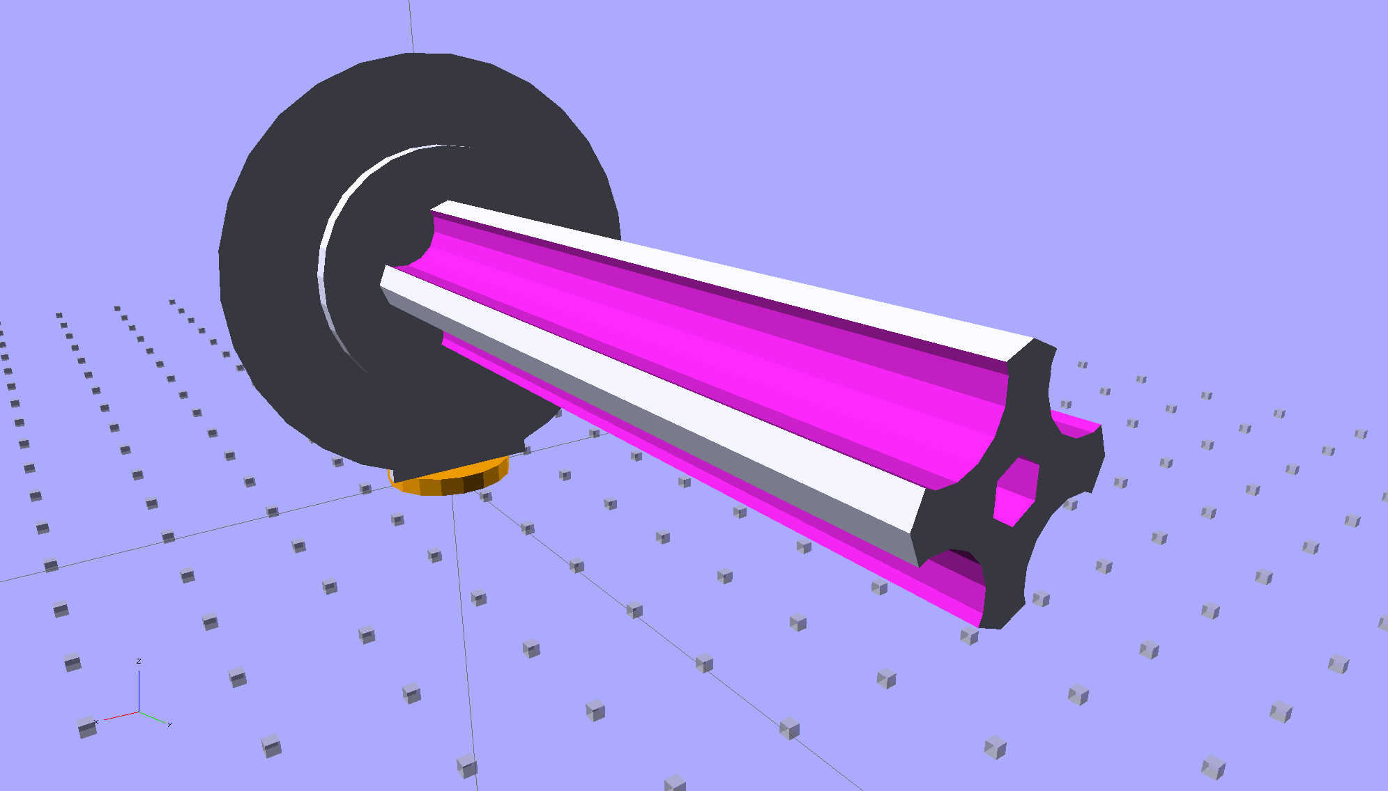
The solid model shows off the fluted rod that passes through the spool:
Large Spool Adapter – solid model – mount
It’s more impressive from the other end:
Large Spool Adapter – solid model – spool end
The first pass at the rod had six flutes, but that seemed unreasonably fine; now it has four. The round base on the rod provides more griptivity to the platform while building and has enough space for the two alignment pins that position it in the middle of the dome:
Large Spool Adapter – solid model – alignment holes
The dome gets glued to the rod base plate:
Large spool adapter – clamped
The spool pin hole is a snug fit around the pin on the sewing machine, because otherwise it would tend to rotate until the spool pointed to the rear of the machine. The fluted rod is a snug friction fit inside the (cardboard) spool. Some useful dimensions:
Spool pin (on Model 158): 5 mm OD, 40 mm tall
Large spool cores: 16 mm ID, 27 mm OD, 70 mm long
I had all manner of elaborate plans to make an expanding fluted rod, but came to my senses and built the simple version first. If that rod isn’t quite big enough, I can build another adapter, just like this one, only slightly larger. The source code includes a 0.5 mm taper, which may suffice.
Back in the day, shortly after the Thing-O-Matic started producing dependable results, one of the very first things I made was a simple adapter to mount large spools on the pin in the most obvious way:
Large spool adapter – old TOM version
Now we all know better than that, my OpenSCAD-fu has grown stronger, and the M2 produces precise results. Life is good!
The OpenSCAD source code:
// Large thread spool adapter
// Ed Nisley - KE4ZNU - August 2014

Layout = "Show";			// Build Show Spindle Spool

Gap = 10.0;					// between pieces in Show

//- Extrusion parameters must match reality!
//  Print with 4 shells and 3 solid layers

ThreadThick = 0.20;
ThreadWidth = 0.40;

HoleWindage = 0.2;			// extra clearance

Protrusion = 0.1;			// make holes end cleanly

AlignPinOD = 1.70;			// assembly alignment pins: filament dia

function IntegerMultiple(Size,Unit) = Unit * ceil(Size / Unit);

//----------------------
// Dimensions

LEN = 0;											// subscripts for cylindrical objects
ID = 1;
OD = 2;

Spindle = [40.0,5.0,14.0];							// spool spindle on sewing machine
Spool = [70.0,16.0,27.0];							// spool core

Taper = 0.50;										// spool diameter increase at base

CottonRoll = [65.0,Spool[OD],45.0];					// thread on spool

Mount = [Spindle[LEN],(Spindle[ID] + 4*ThreadWidth),1.0*Spool[ID]];

Flutes = 4;
Flange = [2.0,Spool[OD],Spool[OD]];

ScrewHole = [10.0,4.0 - 0.7,5.0];					// retaining screw

PinOC = Spool[ID]/4;								// alignment pin spacing

//----------------------
// Useful routines

module PolyCyl(Dia,Height,ForceSides=0) {			// based on nophead's polyholes

  Sides = (ForceSides != 0) ? ForceSides : (ceil(Dia) + 2);

  FixDia = Dia / cos(180/Sides);

  cylinder(r=(FixDia + HoleWindage)/2,
           h=Height,
           $fn=Sides);
}

module ShowPegGrid(Space = 10.0,Size = 1.0) {

  RangeX = floor(100 / Space);
  RangeY = floor(125 / Space);

	for (x=[-RangeX:RangeX])
	  for (y=[-RangeY:RangeY])
		translate([x*Space,y*Space,Size/2])
		  %cube(Size,center=true);

}

//- Locating pin hole with glue recess
//  Default length is two pin diameters on each side of the split

module LocatingPin(Dia=AlignPinOD,Len=0.0) {

	PinLen = (Len != 0.0) ? Len : (4*Dia);

	translate([0,0,-ThreadThick])
		PolyCyl((Dia + 2*ThreadWidth),2*ThreadThick,4);

	translate([0,0,-2*ThreadThick])
		PolyCyl((Dia + 1*ThreadWidth),4*ThreadThick,4);

	translate([0,0,-(Len/2 + ThreadThick)])
		PolyCyl(Dia,(Len + 2*ThreadThick),4);

}

//----------------------
// Spindle

module SpindleMount() {

	render(convexity=4)
	difference() {
		union() {
			resize([0,0,Mount[OD]])							// spool backing plate
				translate([0,CottonRoll[OD]/2,0])
					sphere(d=CottonRoll[OD],center=true);
			translate([0,CottonRoll[OD]/4,0])				// mounting post
				rotate([90,0,0])
					cylinder(d=Mount[OD],h=CottonRoll[OD]/2,center=true);
		}

		translate([0,(2*Mount[LEN] - Protrusion),Mount[OD]/4])				// punch spindle hole
			rotate([90,0,0])
//				PolyCyl(Spindle[ID],2*Mount[LEN],6);
				cylinder(d=Spindle[ID],h=2*Mount[LEN],$fn=6);

		for (i=[-1,1]) {									// punch alignment pin holes
			translate([i*PinOC,CottonRoll[OD]/2,0])
					LocatingPin(Len=Mount[OD]/3);
		}

		translate([0,0,-CottonRoll[OD]])					// remove half toward spool
			cube(2*CottonRoll[OD],center=true);
	}

}

//----------------------
// Spool holder

module SpoolMount() {

	difference() {

		union() {

			translate([0,0,(Flange[LEN] - Protrusion)])
				difference() {
					cylinder(d1=(Spool[ID] + Taper),d2=Spool[ID],h=Spool[LEN],$fn=2*Flutes);						// fit spool ID

					for (a=[0 : 360/Flutes : 360-1])						// create flutes
						rotate(a + 180/Flutes)
							translate([Spool[ID]/2,0,-Protrusion])
								rotate(180/16)
								cylinder(r=Spool[ID]/4,h=(Spool[LEN] + 2*Protrusion),$fn=16);

					translate([0,0,(Spool[LEN] - ScrewHole[LEN])])			// punch screw hole
						PolyCyl(ScrewHole[ID],(ScrewHole[LEN] + Protrusion),6);

				}
			cylinder(d=Flange[OD],h=Flange[LEN]);							// base flange
		}

		for (i=[-1,1])												// punch alignment pin holes
			translate([0,i*PinOC,0])								//  ... orients solid flange up
					LocatingPin(Len=Flange[LEN]);
	}

}


ShowPegGrid();

if (Layout == "Spindle") {
	SpindleMount();
}
if (Layout == "Spool") {
	SpoolMount();
}

if (Layout == "Show") {
	translate([0,Mount[OD]/4,2.0]) {
		rotate([90,0,0])
			SpindleMount();
		translate([0,Gap,CottonRoll[OD]/2])
			rotate([-90,0,0]) rotate(90)
				SpoolMount();
	}
	color("Orange") {
		translate([0,0,2])
			cylinder(d=Spindle[ID],h=Spindle[LEN],$fn=6);
		cylinder(d=Spindle[OD],h=2.0,$fn=18);
	}

}

if (Layout == "Build") {
	translate([-5,0,0])
		rotate(90)
			SpindleMount();
	translate([Flange[OD]/2,0,0])
			SpoolMount();
}
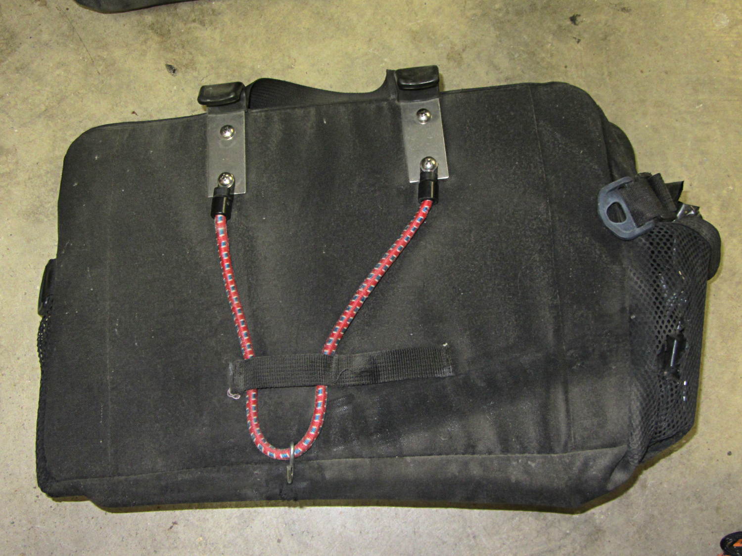
The elastic cord behind the left-side under-seat Easy Reacher pack on my Tour Easy snapped some time ago, probably due to wear against the brace I installed to keep it from flopping around. Quite contrary to what I expected, the repair turned out to be almost trivially easy.
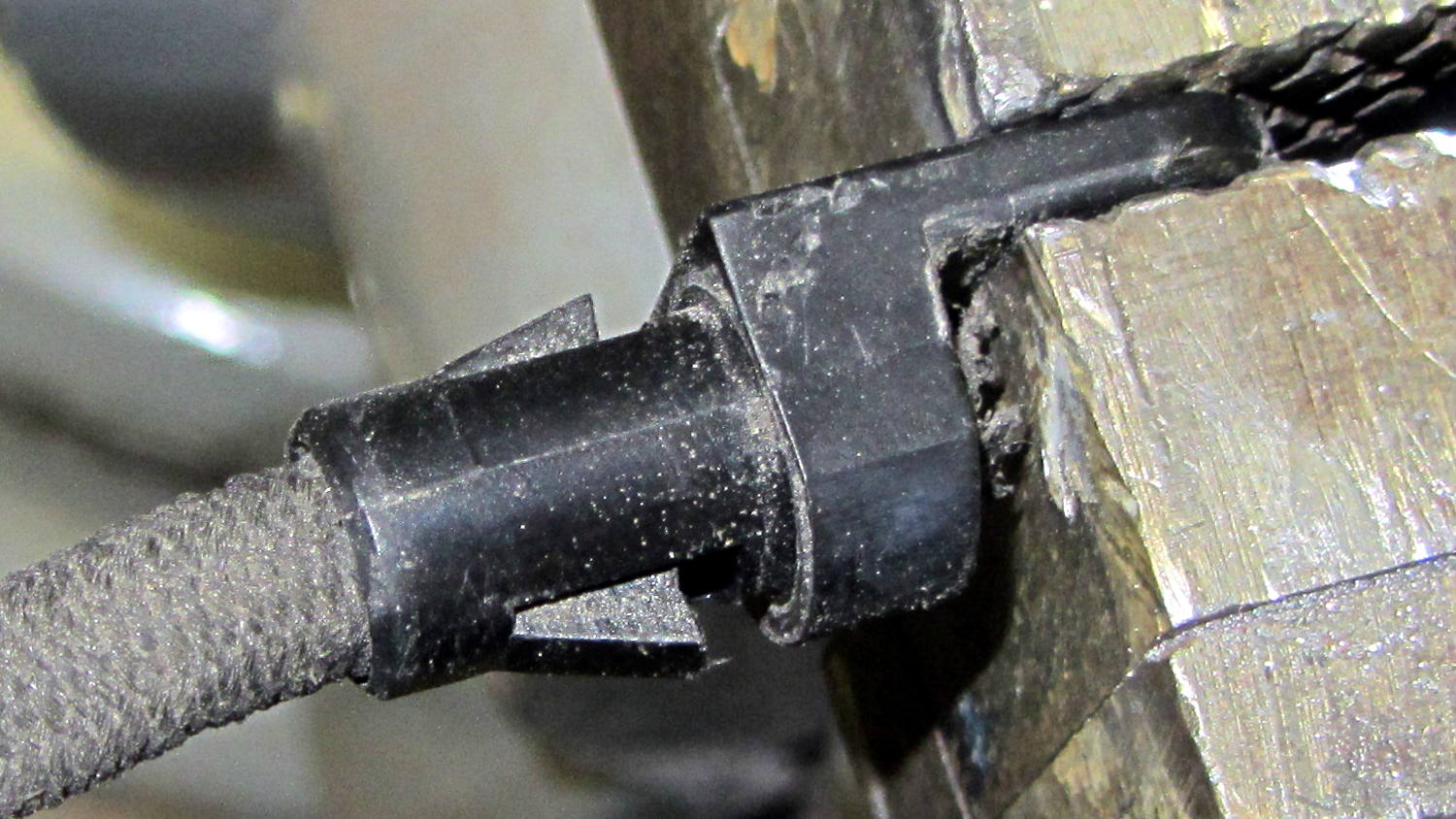
The cord terminates in a pair of plastic lugs, each with a ferrule that slipped off under moderate persuasion to reveal a pair of wedges that engaged the cord:
Easy Reacher pack – elastic cord clamp
I expected the ferrule to have a positive lock engaging those wedges, but, nope, there’s (at most) a small ridge. Pry the wedges out and the cord slides out of the lug without a protest; the wedges don’t quite meet in the middle with the ferrule in place and there’s plenty of retention force on that flexy cord.
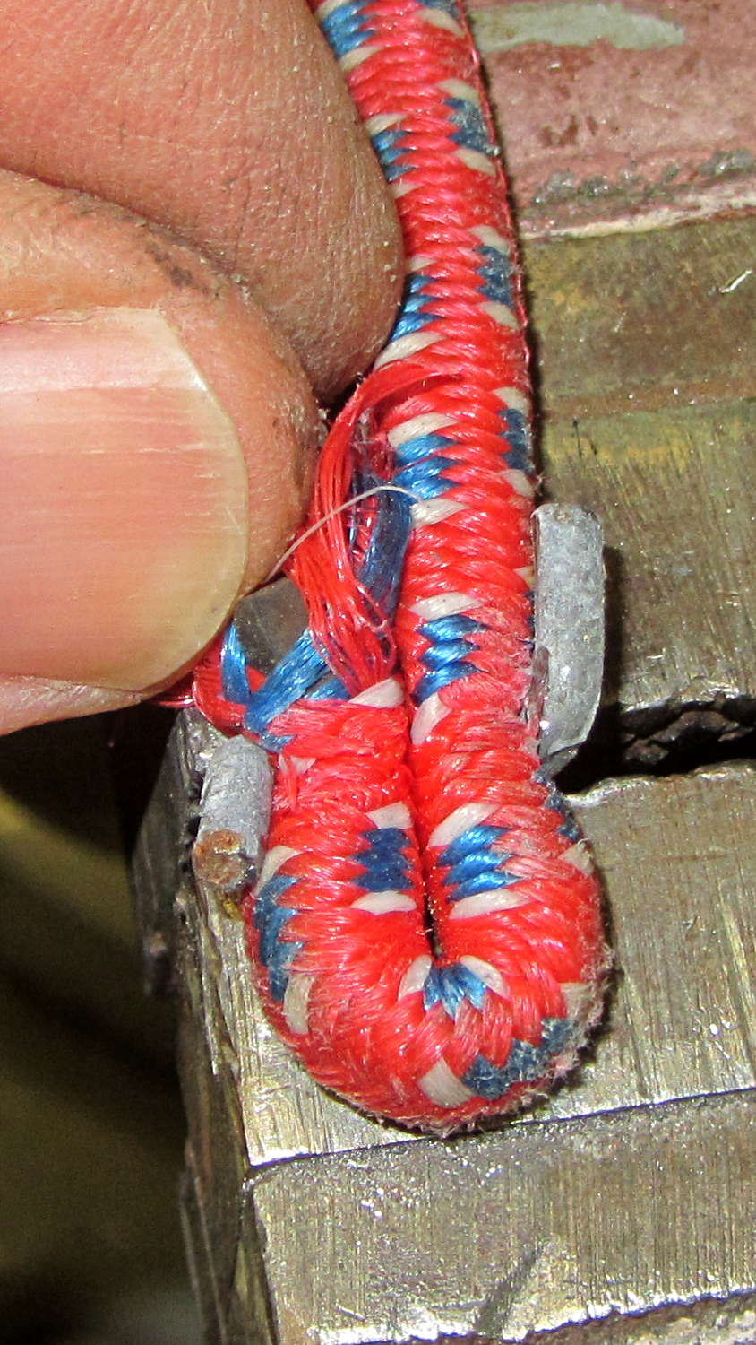
One of the shorter bungie cords in my collection turned out to be exactly the right diameter and length, with ends secured in its hooks using a simple crimped wire. Bending the ends of the wire at right angles freed the cord from its embrace:
Easy Reacher pack – unclamping new elastic cord
The original stainless steel hook lies by the edge of the road along my usual bicycling route, but a slightly reshaped S hook (made, alas, of ordinary steel) fits around the cord well enough. When this one rusts away, I have plenty more.
Insert cord into lugs, push ferrules over locking wedges, remove one ferrule and lug, install reshaped S hook, reinstall lug and ferrule, install new cord on pack:
Easy Reacher pack – new elastic cord
Install pack on bike: done!
I have no explanation for how well this worked out; I fear the Universe is saving up spit for something truly awful.
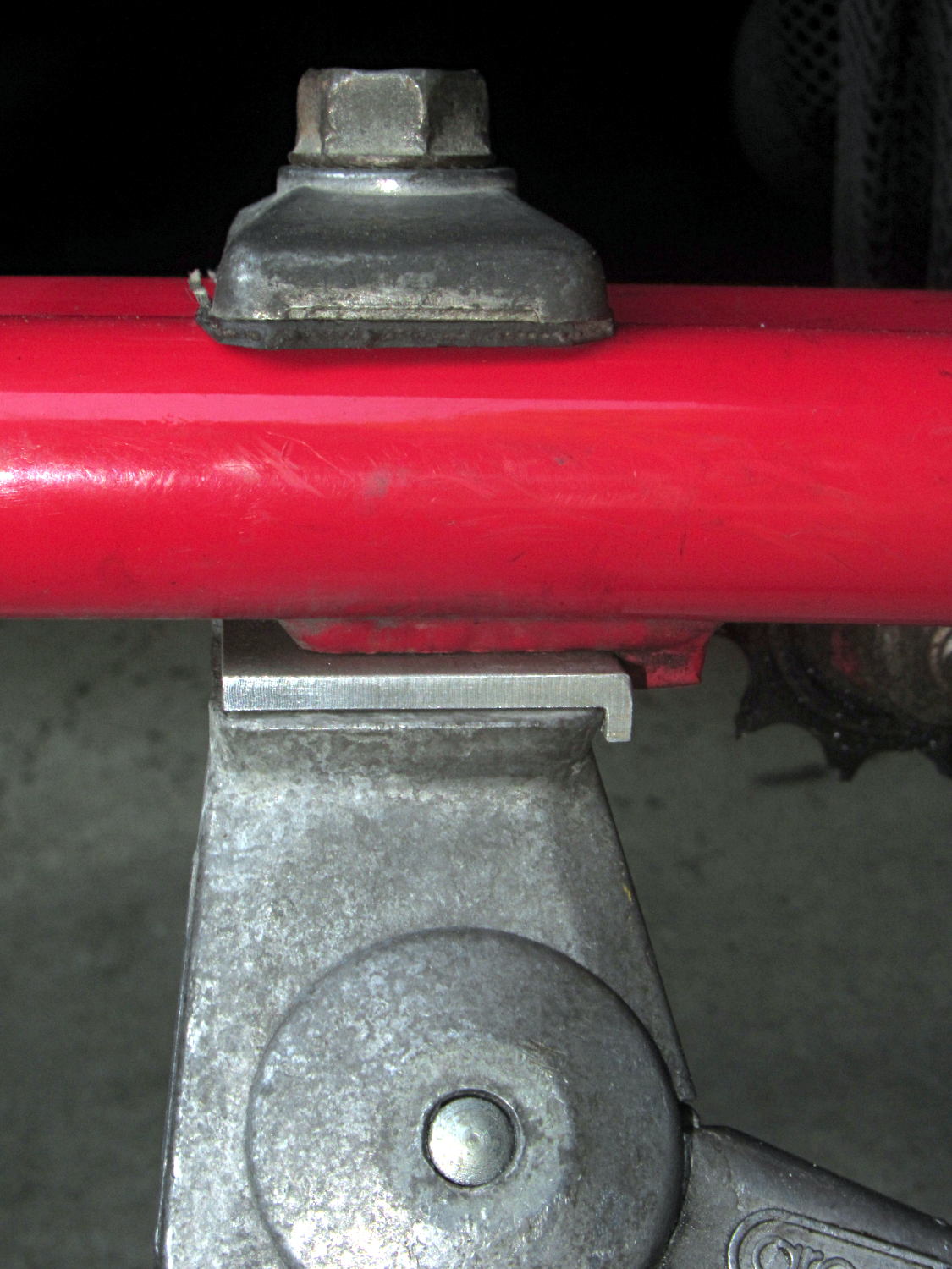
The venerable Greenfield kickstand on my Tour Easy doesn’t quite match the mounting plate under the frame, with the result that it can pivot just enough to make the bike tippy with a moderate load in the rear panniers. I’ve carried a small block to compensate for sloping ground, but I finally got around to fixing the real problem.
The solution turned out to be a spacer plate that fills the gap between the back of the kickstand casting and the transverse block brazed to the mounting plate:
Tour Easy kickstand adapter plate
That little lip is 2 mm wide, so it’s not off by much.
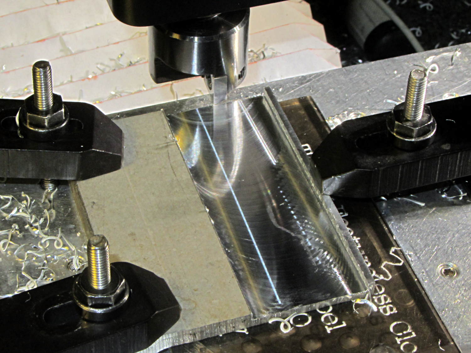
The aluminum came from a Z-shaped post that contributed its legs to a previous project. I flycut the stub of one leg flush with the surface, then flycut a slot 2 mm from the edge:
Tour Easy kickstand adapter – flycutting recess
For no reason whatsoever, the width of that slot turned out exactly right.
Bandsaw along the left edge of the slot, bandsaw the plate to length, square the sides, break the edges, mark the actual location of the mounting plate hole, drill, and it’s done!
An identical Greenfield kickstand on Mary’s identical (albeit smaller) Tour Easy (the bikes have consecutive serial numbers) fits perfectly, so I think this is a classic case of tolerance mismatch.
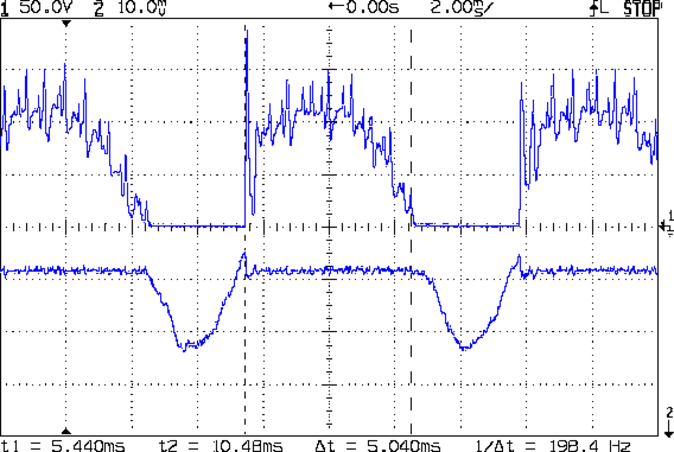
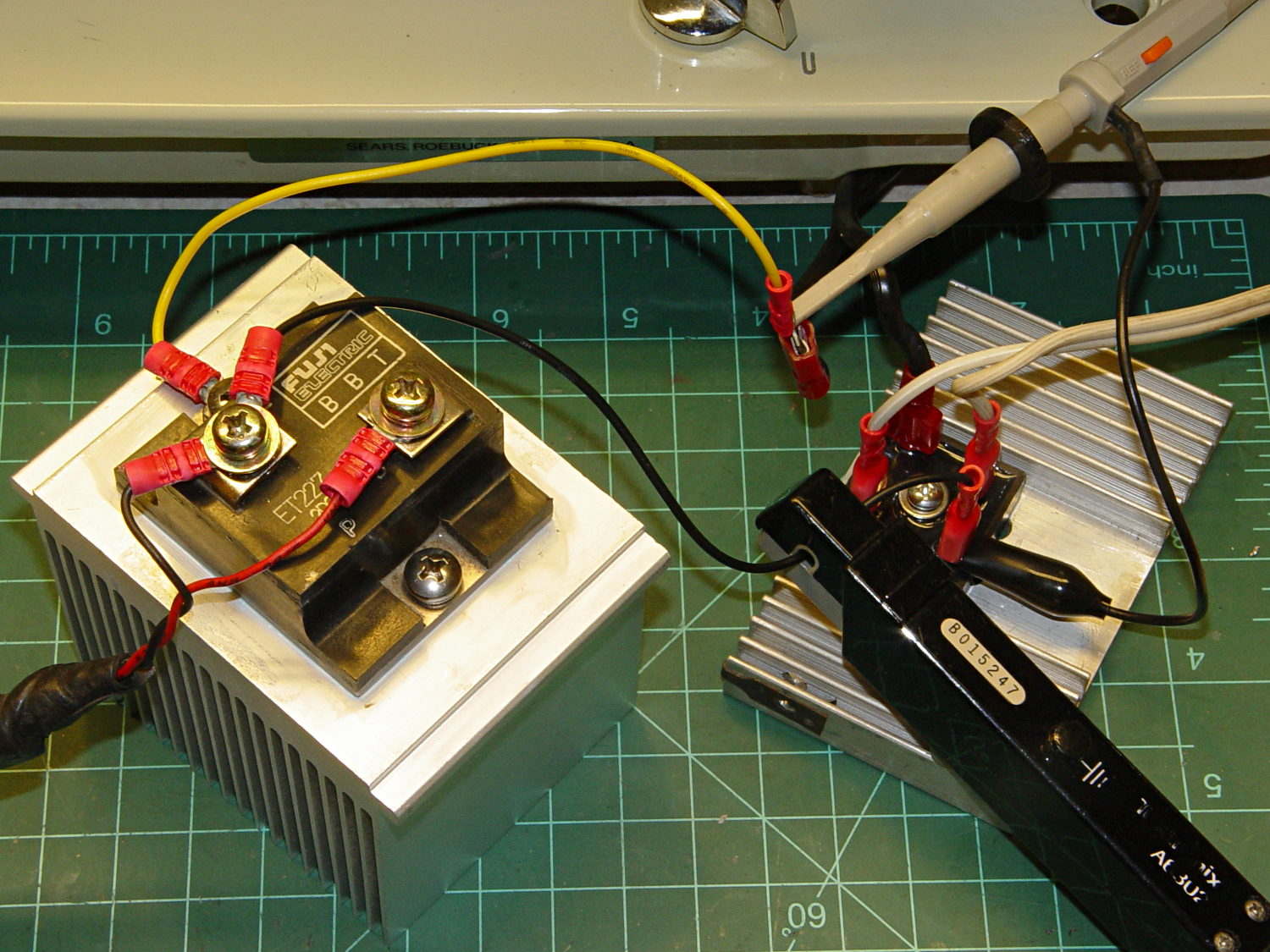
The motor current (200 mA/div) never goes to zero, but the ET227 collector voltage hits zero as the transistor saturates: the motor winding soaks up all the available line voltage and the transistor dissipation drops close to zero. The datasheet suggests VCE(sat) < 0.1 V for IC < 5 A, albeit with IB = 30 A (!).
The ET227 base drive was 77 mA, measured on a better meter than the low-resolution one in the power supply, and the transistor gain works out to 8 = 620 mA / 77 mA along those flat tops.
Eyeballometrically speaking, the dissipation averages 50 W = 90 V x 620 mA during those spiky sections where the transistor must absorb the difference between the line voltage and the motor voltage. The cursors say that takes 5 ms of the 8.3 ms period of the 120 Hz full wave rectified power, so the duty cycle is 42% and the average average dissipation works out to 20 W. That’s still enough to warm up that big heatsink; the motor driver will need a thermal sensor and a quiet fan.
That commutation noise looks pretty scary, doesn’t it?
The test setup:
Kenmore 158 – AC motor FW ET227 drive – test setup
The bridge rectifier doesn’t really need a heatsink, but it looked better for a Circuit Cellar picture…
Took a picture of the sewing machine setup with the Sony DSC-F717, transferred it into DigiKam, got the “done transferring, you can disconnect the camera” message, believed it, disconnected the camera, deleted the image file, and then discovered that DigiKam mislaid the image file.
Rather than re-set-up and re-take the shot, I followed my own directions and recovered the image from the Memory Stick:
dmesg | tail
[43176.079853] usb 2-1.6.3: New USB device strings: Mfr=1, Product=2, SerialNumber=0
[43176.079855] usb 2-1.6.3: Product: Sony PTP
[43176.079856] usb 2-1.6.3: Manufacturer: Sony
[43198.073652] usb 2-1.6.3: USB disconnect, device number 22
[43333.788533] sd 9:0:0:0: [sdc] 1947648 512-byte logical blocks: (997 MB/951 MiB)
[43333.803292] sd 9:0:0:0: [sdc] No Caching mode page found
[43333.803299] sd 9:0:0:0: [sdc] Assuming drive cache: write through
[43333.824681] sd 9:0:0:0: [sdc] No Caching mode page found
[43333.824688] sd 9:0:0:0: [sdc] Assuming drive cache: write through
[43333.825491]  sdc: sdc1
sudo dd if=/dev/sdc of=/tmp/pix.bin bs=1M
^C615+0 records in
614+0 records out
643825664 bytes (644 MB) copied, 38.5841 s, 16.7 MB/s
strings -t x pix.bin | grep Exif | head
  68006 Exif
 208006 Exif
 3f8005 _Exif
 7b8006 Exif
13d8006 Exif
15b0005 wExif
1798005 CExif
19c0006 Exif
1b90006 Exif
1f98005 %Exif
dd if=pix.bin of=image03.jpg bs=$((16#1000)) count=1K skip=$((16#3f8))
1024+0 records in
1024+0 records out
4194304 bytes (4.2 MB) copied, 0.0121431 s, 345 MB/s
display image03.jpg
convert image03.jpg dsc00656.jpg
Obviously, there was a bit more flailing around than you see here, but that’s the gist of the adventure. For what it’s worth, image01 was a random blurred shot and image02 is the ID picture I keep on all my cameras.
The convert step discards all the junk after the end of the image, so the dsc00656.jpg file doesn’t include anything unexpected.
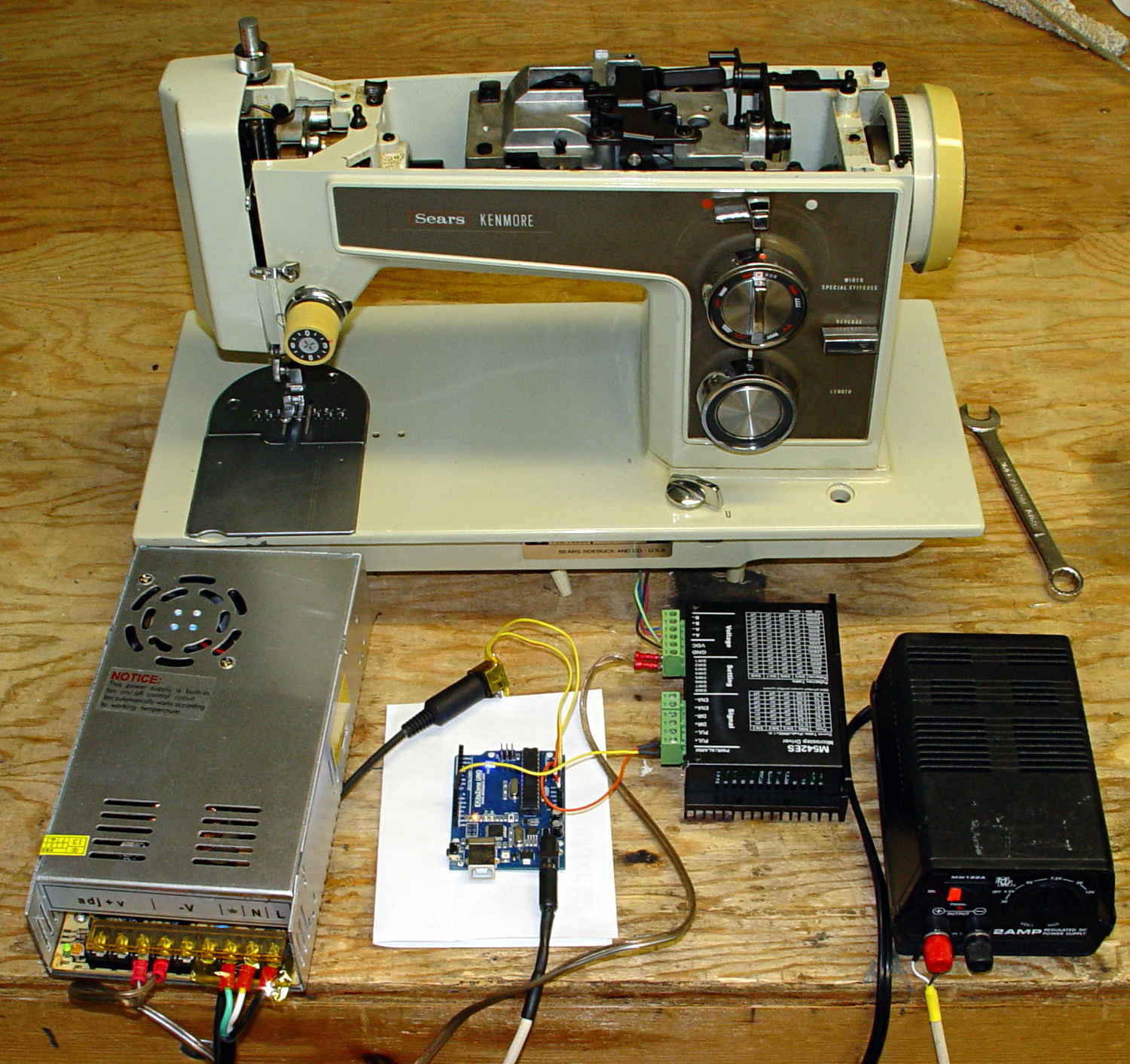
The picture isn’t all that much to look at, even after cropping out the background, but …
Kenmore 158 – stepper drive test
The advantage of the manual method: renewing one’s acquaintance with tools that come in handy for other tasks.
A four-click rotary pushbutton switch actuates the three functions (plus “off”) in sequence:
Flashlight switch – internal wiring
All three lights became intermittent, which suggested a poor return connection at the far end of the battery. The case is, of course, aluminum, with coarse-cut threads that grate as you tighten the parts. I cleaned the crud out of the threads, anointed them with Ox-Gard compound, and discovered that the laser and UV LEDs were still flaky.
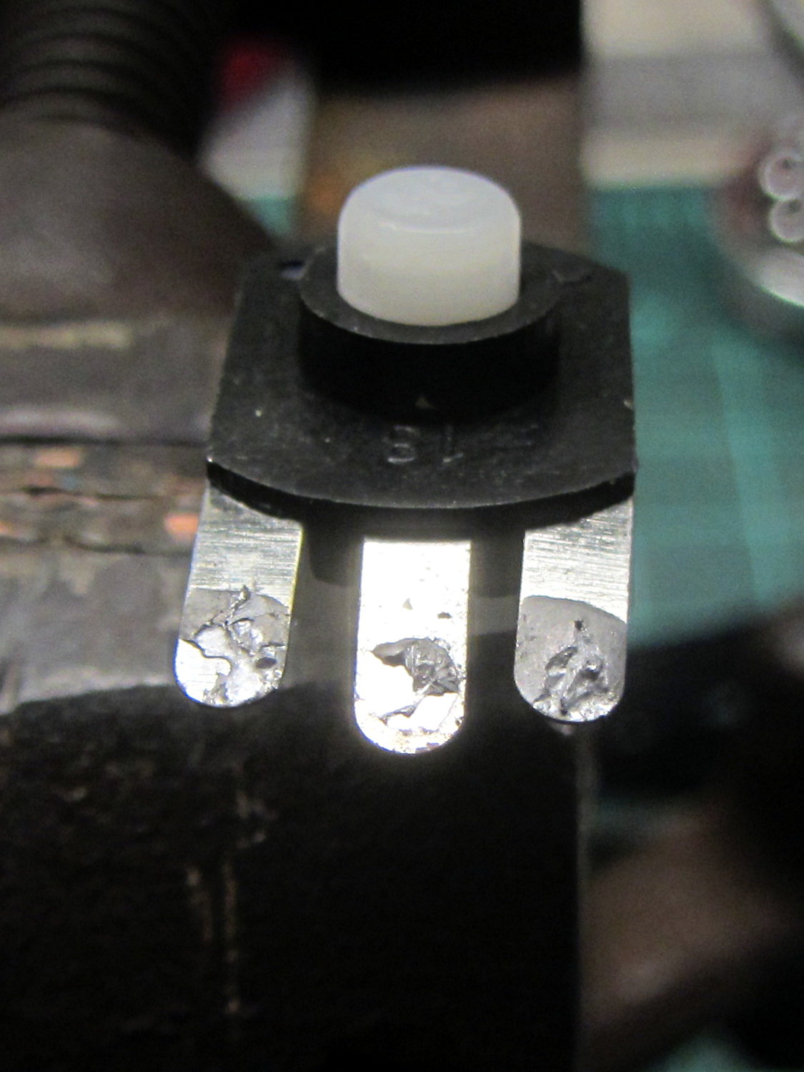
Taking the thing apart and unsoldering the switch connections revealed the problem:
Flashlight switch – bad solder joints
Yup, two lousy solder joints. They’re not exactly cold solder joints, because there’s not really a joint there to begin with; the switch tabs never got hot enough to bond with the molten solder before it cooled.
A dab of flux and touch from a hot soldering iron solved that problem.
Assemble in reverse order and it works better than it ever did before!