The Smell of Molten Projects in the Morning

Ed Nisley's Blog: Shop notes, electronics, firmware, machinery, 3D printing, laser cuttery, and curiosities. Contents: 100% human thinking, 0% AI slop.

Author: Ed

  • Kenmore 158 Needle LEDs: First Light

    With the boost converter mounted and the needle LEDs wired up:

     Kenmore 158 Needle Light - heatsink
    Kenmore 158 Needle Light – heatsink

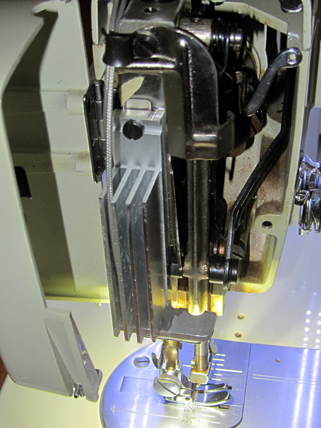
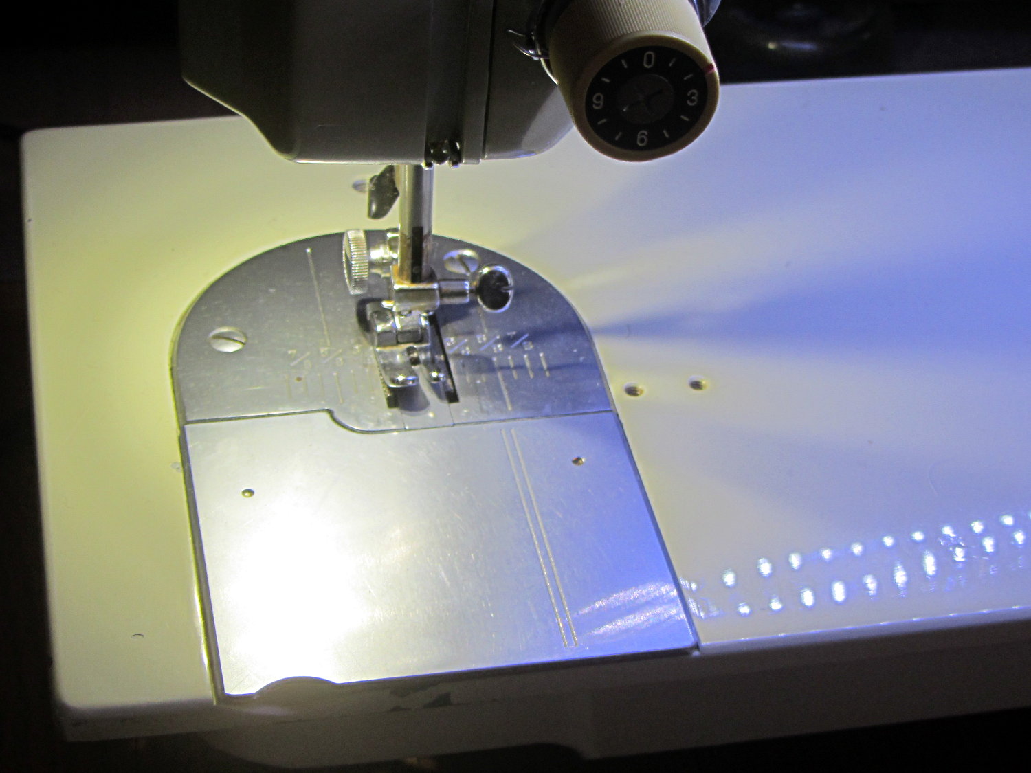
    The Kenmore 158 sewing machine crash test dummy has plenty of light:

    Kenmore 158 LED Lighting - first light
    Kenmore 158 LED Lighting – first light

    Well, as long as you don’t mind the clashing color balance. The needle LEDs turned out warmer than I expected, but Mary says she can cope. I should build a set of warm-white LED strips when it’s time to refit her real sewing machine and add another boost supply to drive them at their rated current.

    Much to our relief, the two LEDs at the needle don’t cast offensively dark shadows:

    Kenmore 158 LED Lighting - detail
    Kenmore 158 LED Lighting – detail

    All in all, it looks pretty good.

  • Generic PCB Holder: Boost Power Supply

    The DC-DC boost power supply for the LED needle lights has four mounting holes, two completely blocked by the heatsink and the others against components with no clearance for screw heads, soooo

    3D printing to the rescue:

    Boost converter - installed
    Boost converter – installed

    Now that the hulking ET227 operates in saturation mode, I removed the blower to make room for the power supply. Two strips of double-stick foam tape fasten the holder to the removable tray inside the Dell GX270’s case.

    It’s basically a rounded slab with recesses for the PCB and clearance for solder-side components:

    Boost converter mount - as printed
    Boost converter mount – as printed

    The solid model shows the screw holes sitting just about tangent to the PCB recess:

    XW029 Booster PCB Mount
    XW029 Booster PCB Mount

    That’s using the new OpenSCAD with length scales along each axis; they won’t quite replace my layout grid over the XY plane, but they certainly don’t require as much computation.

    I knew my lifetime supply of self-tapping hex head 4-40 screws would come in handy for something:

    Boost converter in mount
    Boost converter in mount

    The program needs to know the PCB dimensions and how much clearance you want for the stuff hanging off the bottom:

    PCBoard = [66,35,IntegerMultiple(1.8,ThreadThick)];
    
    BottomParts = [[1.5,-1.0,0,0],	// xyz offset of part envelope
    				[60.0,37.0,IntegerMultiple(3.0,ThreadThick)]];	// xyz envelope size (z should be generous)
    

    That’s good enough for my simple needs.

    The hole locations form a list-of-vectors that the code iterates through:

    Holes = [			// PCB mounting screw holes: XY + rotation
    		[Margin - ScrewOffset,MountBase[Y]/2,180/6],
    		[MountBase[X] - Margin + ScrewOffset/sqrt(2),MountBase[Y] - Margin + ScrewOffset/sqrt(2),15],
    		[MountBase[X] - Margin + ScrewOffset/sqrt(2),Margin - ScrewOffset/sqrt(2),-15],
    		];
    
    ... snippage ...
    
    for (h = Holes) {
    	translate([h[X],h[Y],-Protrusion]) rotate(h[Z])
    		PolyCyl(Tap4_40,MountBase[Z] + 2*Protrusion,6);
    }
    

    That’s the first occasion I’ve had to try iterating a list and It Just Worked; I must break the index habit. The newest OpenSCAD version has Python-ish list comprehensions which ought to come in handy for something.

    The “Z coordinate” of each hole position gives its rotation, so I could snuggle them up a bit closer to the edge by forcing the proper polygon orientation. The square roots in the second two holes make them tangent to the corners of the PCB, rather than the sides, which wasn’t true for the first picture. Fortunately, the washer head of those screws turned out to be just big enough to capture the PCB anyway.

    The OpenSCAD source code:

    // PCB mounting bracket for XW029 DC-DC booster
    // Ed Nisley - KE4ZNU - January 2015
    
    Layout = "Build";			// PCB Block Mount Build
    
    //- Extrusion parameters must match reality!
    //  Print with 4 shells and 3 solid layers
    
    ThreadThick = 0.20;
    ThreadWidth = 0.40;
    
    HoleWindage = 0.2;			// extra clearance
    
    Protrusion = 0.1;			// make holes end cleanly
    
    AlignPinOD = 1.70;			// assembly alignment pins: filament dia
    
    function IntegerMultiple(Size,Unit) = Unit * ceil(Size / Unit);
    
    X = 0;						// useful subscripts
    Y = 1;
    Z = 2;
    
    //----------------------
    // Dimensions
    
    inch = 25.4;
    
    Tap4_40 = 0.089 * inch;
    Clear4_40 = 0.110 * inch;
    Head4_40 = 0.211 * inch;
    Head4_40Thick = 0.065 * inch;
    Nut4_40Dia = 0.228 * inch;
    Nut4_40Thick = 0.086 * inch;
    Washer4_40OD = 0.270 * inch;
    Washer4_40ID = 0.123 * inch;
    
    PCBoard = [66,35,IntegerMultiple(1.8,ThreadThick)];
    
    BottomParts = [[1.5,-1.0,0,0],				// xyz offset of part envelope
    				[60.0,37.0,IntegerMultiple(3.0,ThreadThick)]];			// xyz envelope size (z should be generous)
    
    Margin = IntegerMultiple(Washer4_40OD,ThreadWidth);
    
    MountBase = [PCBoard[X] + 2*Margin,
    			PCBoard[Y] + 2*Margin,
    			IntegerMultiple(5.0,ThreadThick) + PCBoard[Z] + BottomParts[1][Z]
    			];
    echo("Mount base: ",MountBase);
    
    ScrewOffset = Clear4_40/2;
    
    Holes = [									// PCB mounting screw holes: XY + rotation
    		[Margin - ScrewOffset,MountBase[Y]/2,180/6],
    		[MountBase[X] - Margin + ScrewOffset/sqrt(2),MountBase[Y] - Margin + ScrewOffset/sqrt(2),15],
    		[MountBase[X] - Margin + ScrewOffset/sqrt(2),Margin - ScrewOffset/sqrt(2),-15],
    		];
    
    CornerRadius = Washer4_40OD / 2;
    
    //----------------------
    // Useful routines
    
    module PolyCyl(Dia,Height,ForceSides=0) {			// based on nophead's polyholes
    
      Sides = (ForceSides != 0) ? ForceSides : (ceil(Dia) + 2);
    
      FixDia = Dia / cos(180/Sides);
    
      cylinder(r=(FixDia + HoleWindage)/2,
               h=Height,
               $fn=Sides);
    }
    
    module ShowPegGrid(Space = 10.0,Size = 1.0) {
    
      RangeX = floor(100 / Space);
      RangeY = floor(125 / Space);
    
    	for (x=[-RangeX:RangeX])
    	  for (y=[-RangeY:RangeY])
    		translate([x*Space,y*Space,Size/2])
    		  %cube(Size,center=true);
    
    }
    
    //----------------------
    // Build things
    
    module PCB() {
    
    	union() {
    		cube(PCBoard);
    		translate(BottomParts[X] - [0,0,BottomParts[1][Z]])
    			cube(BottomParts[Y] + [0,0,Protrusion]);
    	}
    
    }
    
    module Block() {
    	translate([MountBase[X]/2,MountBase[Y]/2,0])
    		hull()
    			for (i = [-1,1], j = [-1,1])
    				translate([i*(MountBase[X]/2 - CornerRadius),j*(MountBase[Y]/2 - CornerRadius)],0)
    					cylinder(r=CornerRadius,h=MountBase[Z] - Protrusion,$fn=8*4);
    }
    
    module Mount() {
    
    	difference() {
    		Block();
    
    		translate([MountBase[X]/2 - PCBoard[X]/2 + BottomParts[0][X] - Protrusion,
    					-MountBase[Y]/2,
    					MountBase[Z] - PCBoard[Z] - BottomParts[1][Z]])
    			cube([BottomParts[1][X] + 2*Protrusion,
    					2*MountBase[Y],
    					2*BottomParts[1][Z]]);
    
    		translate([MountBase[X]/2 - PCBoard[X]/2,		// PCB recess
    					MountBase[Y]/2 - PCBoard[Y]/2,
    					MountBase[Z] - PCBoard[Z]])
    			PCB();
    		for (h = Holes) {
    			translate([h[X],h[Y],-Protrusion]) rotate(h[Z])
    				PolyCyl(Tap4_40,MountBase[Z] + 2*Protrusion,6);
    		}
    	}
    
    }
    
    //ShowPegGrid();
    
    if (Layout == "PCB")
    	PCB();
    
    if (Layout == "Block")
    	Block();
    
    if (Layout == "Mount")
    	Mount();
    
    if (Layout == "Build")
    	translate([-MountBase[X]/2,-MountBase[Y]/2,0])
    	Mount();
    
  • Wider Borders in XFCE / Xubuntu

    A longstanding Xubuntu / XFCE UI problem has been single-pixel window borders that make click-and-drag resizing essentially impossible. The reason it’s a longstanding problem has been the developers’ unflinching response to any and all issues raised on the bug tracker:

    That discussion may be illuminating.

    I had never looked for the XFCE theme-building documentation (and, thus, never found any), because building a whole new theme would be a lot of work just to resize the damn borders. It should be feasible to tweak only the borders of an existing theme, but … I stalled.

    Repeatedly. On every single version of Xubuntu that’s come along.

    Fortunately, someone recently did the legwork and summarized the method, which I slightly adapted:

    cd /usr/share/themes/
    sudo cp -a Greybird-compact/ Greybird-wide
    cd Greybird-wide/xfwm4
    for f in bottom left right ; do sudo cp ../../Daloa/xfwm4/${f}* . ; done
    sudo sed -i -e 's/C0C0C0/CECECE/' *xpm
    sudo sed -i -e 's/A0A0FF/7C7C7C/' *xpm
    sudo sed -i -e 's/E0E0FF/E0E0E0/' *xpm
    

    The exact color mapping depends on which two themes you’re using. You can also specify GTK element colors, which seems like a better way to do it. Maybe next time.

    Apparently, the corresponding PNG files contain transparency information for the XPM files, but I haven’t bothered to investigate how that works or what might happen if I tweaked them.

    Then you select the new Graybird-wide theme and It Just Works.

    Sheesh & similar remarks…

  • Dual Monitors Redux

    My trusty 1050×1680 portrait monitor began resetting itself, which probably indicates failing capacitors in the power supply or logic board; eBay has capacitor kits, but it may not be worthwhile fixing the poor thing. I snagged a new 2560×1440 Dell U2713HM monitor, added a dual-Displayport PNY NVS310 video card, told Xubuntu 14.04LTS to use nVidia’s binary driver, and, somewhat to my astonishment, It Just Worked.

    The xrandr report:

    Screen 0: minimum 8 x 8, current 4000 x 2560, maximum 16384 x 16384
    DP-0 disconnected primary (normal left inverted right x axis y axis)
    DP-1 disconnected (normal left inverted right x axis y axis)
    DP-2 connected 2560x1440+0+0 (normal left inverted right x axis y axis) 597mm x 336mm
       2560x1440      60.0*+
       1920x1200      59.9
       1920x1080      60.0     59.9     50.0     24.0     60.1     60.0     50.0
       1680x1050      60.0
       1600x1200      60.0
       1280x1024      75.0     60.0
       1280x800       59.8
       1280x720       60.0     59.9     50.0
       1152x864       75.0
       1024x768       75.0     60.0
       800x600        75.0     60.3
       720x576        50.0     50.1
       720x480        59.9     60.1
       640x480        75.0     59.9     59.9
    DP-3 connected 1440x2560+2560+0 left (normal left inverted right x axis y axis) 597mm x 336mm
       2560x1440      60.0*+
       1920x1200      59.9
       1920x1080      60.0     59.9     50.0     24.0     60.1     60.0     50.0
       1680x1050      60.0
       1600x1200      60.0
       1280x1024      75.0     60.0
       1280x800       59.8
       1280x720       60.0     59.9     50.0
       1152x864       75.0
       1024x768       75.0     60.0
       800x600        75.0     60.3
       720x576        50.0     50.1
       720x480        59.9     60.1
       640x480        75.0     59.9     59.9
    

    Inexplicably, xsetwacom once again expects the "HEAD-0" parameter that was "DP1" the last time around:

    xsetwacom --verbose set "Wacom Graphire3 6x8 stylus" MapToOutput "HEAD-0"
    xsetwacom --verbose set "Wacom Graphire3 6x8 eraser" MapToOutput "HEAD-0"
    

    The new display presents crisp characters; seeing 140 source code lines at once is wonderful.

  • Last of the Energizer CR2032 Cells

    All three Energizer CR2032 lithium cells installed at the end of November failed in December, with this being the most dramatic example:

    Attic - Insulated Box - Early battery failure
    Attic – Insulated Box – Early battery failure

    Now, granted, it was mighty chilly in the attic, but failing after 18 hours seems unreasonable. So much for last month’s data.

    I’ve started a batch of Maxell cells with the more reasonable date code 3O, which seems to indicate a manufacturing date of 2013 October.

    We shall see…

  • If You See Something, Say Something

    Nah, that can’t possibly be a …

    Mannequin head - 1
    Mannequin head – 1

    Tell me it’s not a really bad wig …

    Mannequin head - 2
    Mannequin head – 2

    Gently now …

    Mannequin head - 3
    Mannequin head – 3

    Whew!

    Found on Old Mill Road, just downstream of the Red Oaks Mill dam; the Mighty Wappingers Creek flows on the left.

    That’s all I have to say…

  • Thunderbird UI Tweakage

    If you want to change the font in all of Thunderbird’s UI, you must perform this magic ritual:

    • Create the file chrome/userChrome.css in wherever they’ve hidden your profile folder (for Ubuntu 14.04, it’s ~/.thunderbird)
    • Then put this incantation inside:
    /* Global UI font */
    /* may need !important on each entry */
    * { font-size: 14pt ;
      font-family: Arial Narrow ;
    }
    

    As nearly as I can tell, you don’t need the !important tag on the top-level entry, but I don’t profess to grok Mozilla-flavored CSS.

    Useful properties:

    • font-weight: normal | bold | light
    • font-style: normal | italic | oblique

    Maybe you can do the whole font thing in one shot, but I haven’t tried.

    The changes take effect the next time you fire up Thunderbird: dinking with this stuff gets tedious.

    This is way too intricate for mere mortals…