A Hacker News discussion led to the Subpixel Zoo, which led to thinking the patterns might make interesting layered “art”. After fetching the *.webp images and figuring out how to persuade Thunar to display them, the next step was converting them into paths suitable for laser cutting.
Although the images are algorithmically generated in a common layout, figuring out how to get the outlines as paths seemed to require a journey into the depths of the Pygame library and that would turn into a major digression.
Instead, start with one of the webp images:

The deliberate blurring apparently simulates what you see in real life.
Import the image into LightBurn, which converts it to grayscale under the plausible assumption you’re going to engrave the image on something. Then:
- Create a rounded rectangle overlaying the lower-left-most subpixel to good eyeballometric accuracy
- Turn it into a four-element rectangular array, twiddling the center-to-center spacing to match the subpixel layout
- Duplicate those four upward in another array to create a subpixel block, as marked in the upper-left corner of the original image
- Slam another array across the bottom row and upward, twiddling the spacing to match the subpixel block spacing along both axes
Which eventually looks like this:
I made the final array absurdly large, cropped it with a square to match the template I used for the layered paper patterns, resized the result to be 170 mm on a side, then dropped the square into the middle of the template:
One gotcha: crop the subpixels on a Fill layer so LightBurn will close the truncated edges, then put them on a Line layer for cutting. The doc explains why, although it’s not obvious at first, as is the fact that you must delete the group of shapes outside the square before it looks like anything happened during the cut operation.
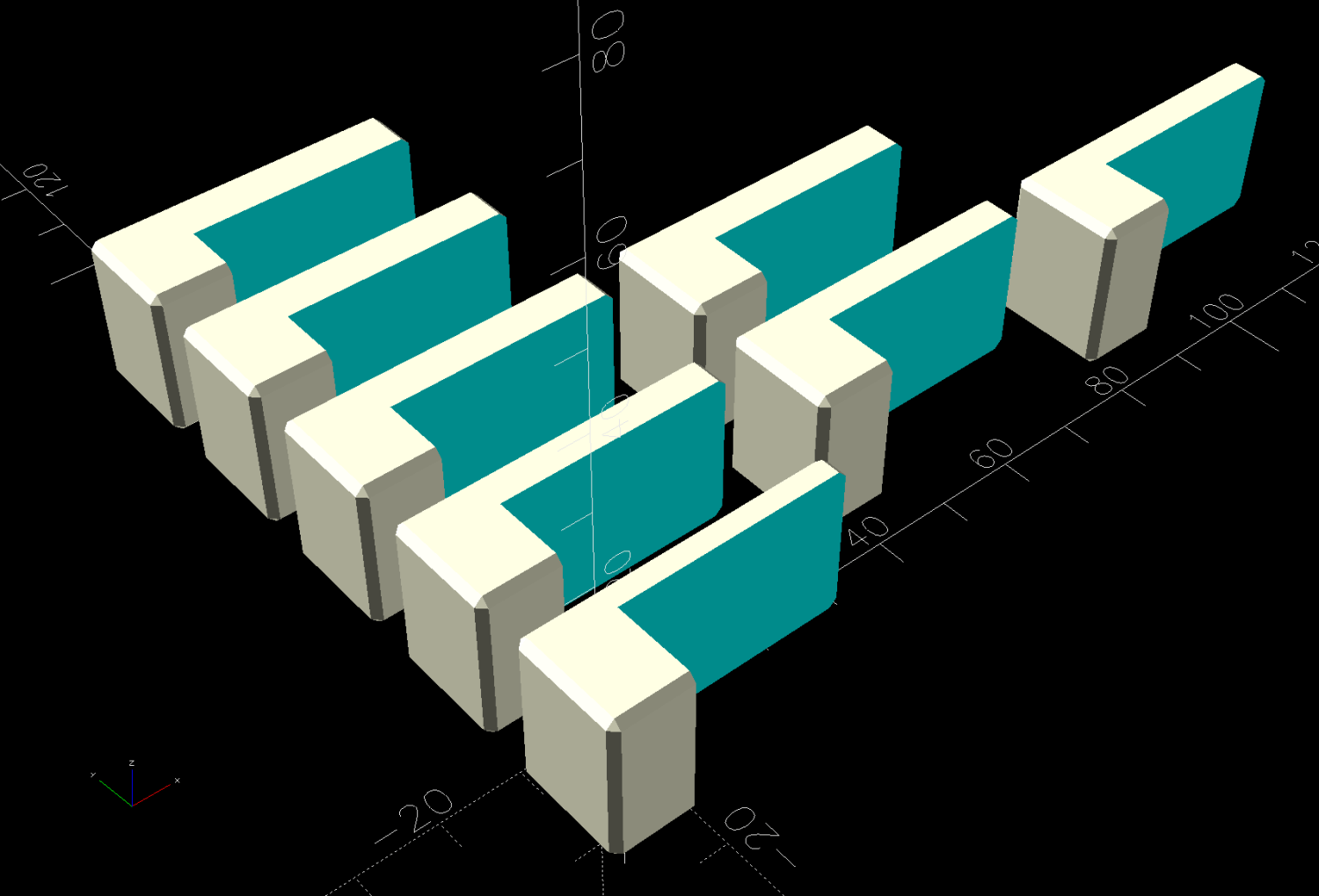
The resulting layout contains all the subpixel rectangles, so it’s what you want for the top black mask layer. Duplicate the pattern and delete the subpixels corresponding to each color, until you have one template for each of the Red / Green / Blue layers:
The blank over on the right is the Yellow layer, which does get a quartet of layer ID holes cut in the lower right corner.
Then it’s just a matter of cutting the blanks, locating the fixture on the platform, dropping the appropriate color sheet in place, cutting it, then assembling the stack in the gluing fixture:
It’s kinda cute, in a techie way.
I did a bunch of layouts, just to see what they looked like:
In person, the RGBY patterns look bright and the RGB patterns seem dull by comparison. I’m using cardstock paper, rather than fancy art paper, which surely makes all the difference.